Content
1 Syllabus
2 Useof Electronics in the
Automobile
3 Anti-lock Breaking
System
4 Electronic Steering
Control
5 Power
Steering
6 Traction Control
7 Electronically Controlled
Suspension
2.
SYLLABUS
UNIT 1: AUTOMOTIVEFUNDAMENTALS
Use of Electronics In The Automobile, Antilock Brake Systems,
(ABS), Electronic steering control, Power steering, Traction
control, Electronically controlled suspension
3.
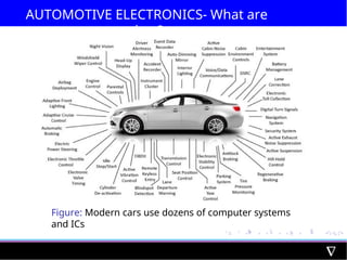
AUTOMOTIVE ELECTRONICS- Whatare
they?
Automotive electronics are specially-designed electronics
intended for use in automobiles
It can be subjected to, and are at, more extreme
temperature ranges than commercial (i.e. normal)
electronics.
“Automotive electronics” are those devices that have either
been designed for or have been adapted for use in
automobile applications
Categories of this include carputers, telematics, and
infotainment systems
Carputers: a combination of the words car and computer
4.
How are theydiffer from normal
electronics?
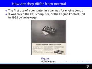
The first use of a computer in a car was for engine control
It was called the ECU computer, or the Engine Control Unit
in 1968 by Volkswagen
Figure:
Volkswagen
5.
How are theydiffer from normal
electronics?
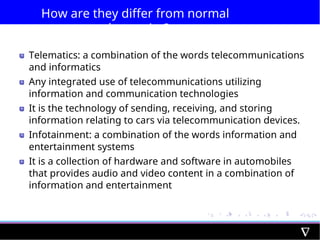
Telematics: a combination of the words telecommunications
and informatics
Any integrated use of telecommunications utilizing
information and communication technologies
It is the technology of sending, receiving, and storing
information relating to cars via telecommunication devices.
Infotainment: a combination of the words information and
entertainment systems
It is a collection of hardware and software in automobiles
that provides audio and video content in a combination of
information and entertainment
6.
How are theydiffer from normal
electronics?
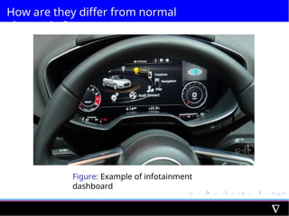
Figure: Example of infotainment
dashboard
Type of AutomotiveElectronics
Engine Electronics
Transmission
Electronics Chassis
Electronics Passive
safety
Driver Assistance
Passenger Comforts
Entertainment
Systems
9.
ABS (Anti-lock Breaking
System)
Anti-lockBraking System;-Also known as anti-skid braking
system
It is an automobile safety system which prevents the locking
of wheels during braking and avoid uncontrolled skidding.
The modern abs system allows steering during braking which
gives more control over the vehicle in case of sudden
braking.
Main Advantage:-better control over the vehicle and
decreases stopping distance
Figure: ABS-
Logo
10.
ABS- Principle ofWorking
Works on the principle of threshold braking and cadence
braking
Cadence braking and threshold braking is a technique in
which a driver applies the brakes and releases it before
locking up the wheel and then applies the brakes and
releases it again before locking.
Process of applying and releasing the brakes on the wheel is
done in pulse form to prevent it from locking and stop
skidding of the vehicle
The ABS system automatically does this cadence braking to
prevent locking of wheel and skidding of vehicle when
brakes are applied.
11.
Why ABS isEssential in Automobiles?
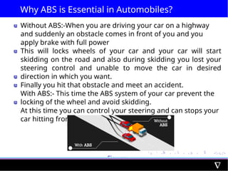
Without ABS:-When you are driving your car on a highway
and suddenly an obstacle comes in front of you and you
apply brake with full power
This will locks wheels of your car and your car will start
skidding on the road and also during skidding you lost your
steering control and unable to move the car in desired
direction in which you want.
Finally you hit that obstacle and meet an accident.
With ABS:- This time the ABS system of your car prevent the
locking of the wheel and avoid skidding.
At this time you can control your steering and can stops your
car hitting from the obstacle
Figure:
Caption
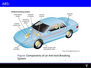
ABS-Main Components
1
2
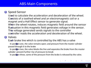
Speed Sensor
Usedto calculate the acceleration and deceleration of the wheel.
Consists of a toothed wheel and an electromagnetic coil or a
magnet and a Hall Effect sensor to generate signal.
When the wheel rotates, induces magnetic field around the sensor
fluctuation in this magnetic field generates voltage in the sensor.
This voltage generated sends signals to the controller
controller reads the acceleration and deceleration of the wheel.
Valves
Each brake line which is controlled by the ABS has a valve
1 In position one, the valve remains open; and pressure from the master cylinder
passed through it to the brake
2 In position two, the valve blocks the line and separates the brake from the master
cylinder–prevent further rise of pressure to break
3 In position three, some of the pressure from the brake is released by the valve.
15.
ABS-Main Components
3
4
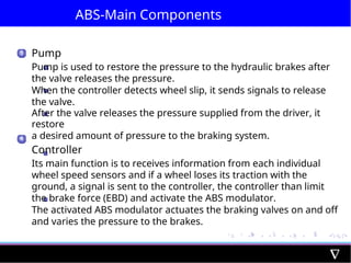
Pump
Pump isused to restore the pressure to the hydraulic brakes after
the valve releases the pressure.
When the controller detects wheel slip, it sends signals to release
the valve.
After the valve releases the pressure supplied from the driver, it
restore
a desired amount of pressure to the braking system.
Controller
Its main function is to receives information from each individual
wheel speed sensors and if a wheel loses its traction with the
ground, a signal is sent to the controller, the controller than limit
the brake force (EBD) and activate the ABS modulator.
The activated ABS modulator actuates the braking valves on and off
and varies the pressure to the brakes.
16.
ABS-Working
The controller(ECU) readsthe signal from each of the speed
sensors of the wheel.
As the brakes are suddenly applied, this makes the wheel to
decelerate at faster rate and may cause the wheel to Lock.
As the ECU reads the signal which indicates the rapid
decrease in the speed of the wheel, it sends signal to the
valve which makes the valve close and the pressure to the
brake pad reduces and prevents the wheel from locking.
The wheel again starts to accelerate, again the signal sends
to the controller, this time it opens the valve, increasing the
pressure to the brake pad and brakes are applied, this again
reduces the speed of the wheel and tries to make it stop.
This process of applying brakes and releasing it happens 15
times in a second when a driver suddenly applies the brake
harder
17.
ABS-The Complete Physics
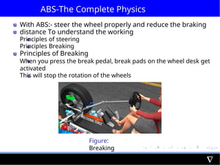
WithABS:- steer the wheel properly and reduce the braking
distance To understand the working
Principles of steering
Principles Breaking
Principles of Breaking
When you press the break pedal, break pads on the wheel desk get
activated
This will stop the rotation of the wheels
Figure:
Breaking
18.
ABS-The Complete Physics
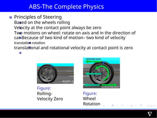
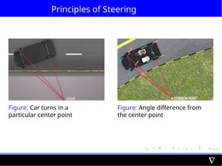
Principlesof Steering
Based on the wheels rolling
Velocity at the contact point always be zero
Two motions on wheel: rotate on axis and in the direction of
car Because of two kind of motion– two kind of velocity
translation rotation
translational and rotational velocity at contact point is zero
Figure:
Rolling-
Velocity Zero
Figure:
Wheel
Rotation
19.
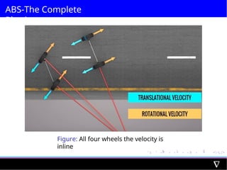
ABS- The CompletePhysics
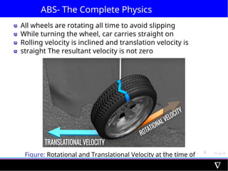
All wheels are rotating all time to avoid slipping
While turning the wheel, car carries straight on
Rolling velocity is inclined and translation velocity is
straight The resultant velocity is not zero
Figure: Rotational and Translational Velocity at the time of
Turning
20.
ABS-The Complete Physics
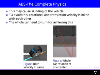
Thismay cause skidding of the vehicle
TO avoid this, rotational and translation velocity is inline
with each other
The whole car need to turn for achieving this
Figure: Both
velocity in same
line
Figure: Whole
car rotation at
one center
point
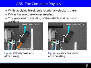
ABS- The CompletePhysics
While applying break-only rotational velocity is there.
Driver has no control over steering
This may lead to skidding of the vehicle and cause of
accident
Figure: Velocity Positions-
After turning
Figure: Velocity Positions-
After breaking
23.
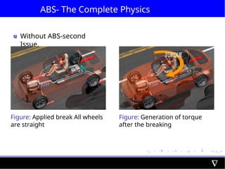
ABS- The CompletePhysics
Without ABS-second
Issue.
Figure: Applied break All wheels
are straight
Figure: Generation of torque
after the breaking
24.
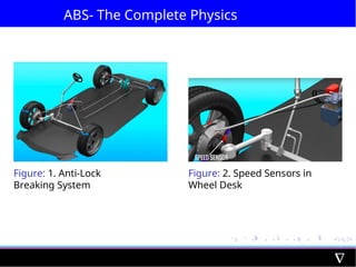
ABS- The CompletePhysics
Figure: 1. Anti-Lock
Breaking System
Figure: 2. Speed Sensors in
Wheel Desk
25.
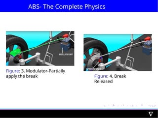
ABS- The CompletePhysics
Figure: 3. Modulator-Partially
apply the break Figure: 4. Break
Released
26.
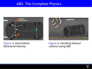
ABS- The CompletePhysics
Figure: 5. Intermittent
Rotational Velocity
Figure: 6. Handling without
collision using ABS
27.
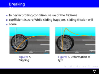
Breaking
Distance
In perfect rollingcondition, value of the frictional
coefficient is zero While sliding happens, sliding friction will
come
12% of slip ratio
Figure: 7.
Slipping
Figure: 8. Deformation of
tyre
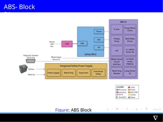
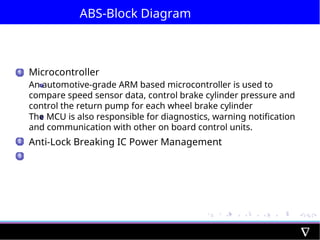
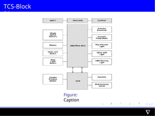
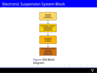
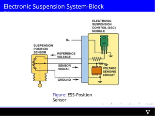
ABS-Block Diagram
1 Microcontroller
Anautomotive-grade ARM based microcontroller is used to
compare speed sensor data, control brake cylinder pressure and
control the return pump for each wheel brake cylinder
The MCU is also responsible for diagnostics, warning notification
and communication with other on board control units.
Anti-Lock Breaking IC Power Management
2
3
30.
ABS- Advantages
1 Itprevents the locking of the wheel and thus eliminates the
chance of skidding.
A better steering control is obtained with the ABS system It
reduces the chance of collision by 30
2
3
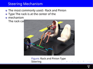
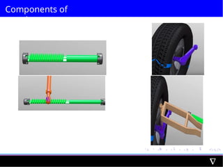
Steering Mechanism
The mostcommonly used:- Rack and Pinion
Type The rack is at the center of the
mechanism
The rack can only move in a straight line
Figure: Rack and Pinion Type
Steering
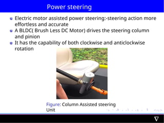
Power steering
Electric motorassisted power steering:-steering action more
effortless and accurate
A BLDC( Brush Less DC Motor) drives the steering column
and pinion
It has the capability of both clockwise and anticlockwise
rotation
Figure: Column Assisted steering
Unit
37.
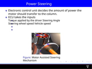
Power Steering
Electronic controlunit decides the amount of power the
motor should transfer to the column.
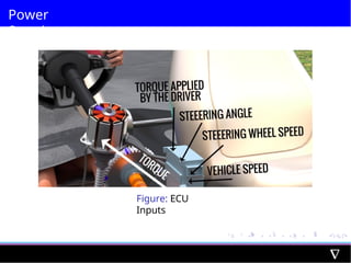
ECU takes the inputs
Torque applied by the driver Steering Angle
Steering wheel speed Vehicle speed
Figure: Motor Assisted Steering
Mechanism
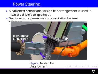
Power Steering
A halleffect sensor and torsion bar arrangement is used to
measure driver’s torque input.
Due to motor’s power assistance rotation become
effortless
Figure: Torsion Bar
Arrangement
40.
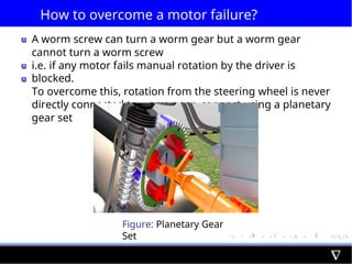
How to overcomea motor failure?
A worm screw can turn a worm gear but a worm gear
cannot turn a worm screw
i.e. if any motor fails manual rotation by the driver is
blocked.
To overcome this, rotation from the steering wheel is never
directly connected to worm gear, connect using a planetary
gear set
Figure: Planetary Gear
Set
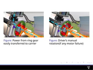
41.
Figure: Power fromring gear
easily transferred to carrier
Figure: Driver’s manual
rotation(if any motor failure)
42.
Power Steering-Block
Diagram
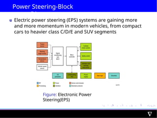
Electric powersteering (EPS) systems are gaining more
and more momentum in modern vehicles, from compact
cars to heavier class C/D/E and SUV segments
Figure: Electronic Power
Steering(EPS)
43.
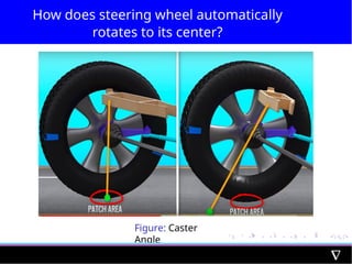
How does steeringwheel automatically
rotates to its center?
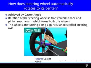
Achieved by Caster Angle
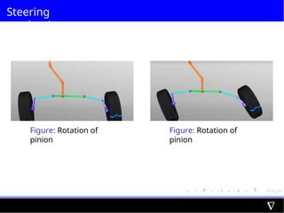
Rotation of the steering wheel is transferred to rack and
pinion mechanism which turns both the wheels
The wheels are turning along a particular axis called steering
axis
Figure: Caster
Angle
44.
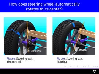
How does steeringwheel automatically
rotates to its center?
Figure: Steering axis-
Theoretical
Figure: Steering axis-
Practical
45.
How does steeringwheel automatically
rotates to its center?
Figure: Caster
Angle
46.
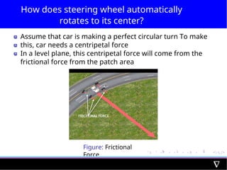
How does steeringwheel automatically
rotates to its center?
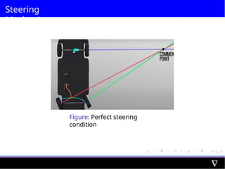
Assume that car is making a perfect circular turn To make
this, car needs a centripetal force
In a level plane, this centripetal force will come from the
frictional force from the patch area
Figure: Frictional
Force
47.
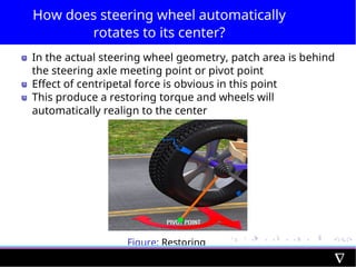
How does steeringwheel automatically
rotates to its center?
In the actual steering wheel geometry, patch area is behind
the steering axle meeting point or pivot point
Effect of centripetal force is obvious in this point
This produce a restoring torque and wheels will
automatically realign to the center
Figure: Restoring
Torque
48.
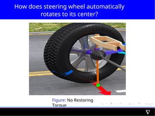
How does steeringwheel automatically
rotates to its center?
Figure: No Restoring
Torque
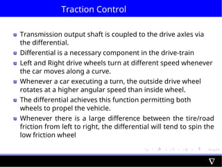
Traction Control
Transmission outputshaft is coupled to the drive axles via
the differential.
Differential is a necessary component in the drive-train
Left and Right drive wheels turn at different speed whenever
the car moves along a curve.
Whenever a car executing a turn, the outside drive wheel
rotates at a higher angular speed than inside wheel.
The differential achieves this function permitting both
wheels to propel the vehicle.
Whenever there is a large difference between the tire/road
friction from left to right, the differential will tend to spin the
low friction wheel
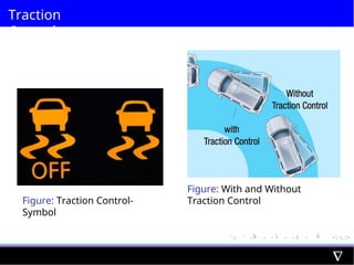
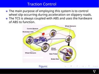
Traction Control
The mainpurpose of employing this system is to control
wheel slip occurring during acceleration on slippery roads.
The TCS is always coupled with ABS and uses the hardware
of ABS to function.
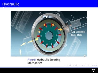
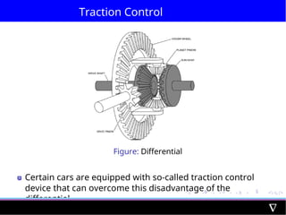
Figure:
Differential
54.
Traction Control
It isexperienced that the wheels of a vehicle spin on the
same location without moving forward when accelerated on
slippery roads like ice-covered roads.
This happens due to the reduced friction.
In such a case, if the speed of rotation of that wheel lowers,
then the wheel achieves its desired tractive force and can
move forward under control.
How TCS works?
TheElectronic Control Unit (ECU) has the module of the
Traction Control System in it.
It compares the vehicle’s drive wheels’ rotational speeds with
the help of the ABS’s wheel speed sensors.
If any of the drive wheels are rotating at exceptionally high
speeds, the TCS considers it as the corresponding wheel’s
spinning.
The TCS, then, immediately sends a signal to apply brakes to
that particular wheel.
Thus, the traction control system avoids the wheel-slip,
allowing the driver to accelerate under control.
Alternate way:- reducing the engine power delivered to the
spinning wheel or cutting off the fuel supply to some engine
cylinders.
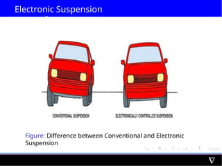
Electronic Suspension
System
Electronic suspensionsare the most advanced suspension
systems available.
Electronic suspensions adjust the feel of the suspension and
vehicle’s ride height to cater to changing road conditions
with ease.
Unlike air suspensions, an electronic suspension modifies
the shocks and/or struts electronically to ensure a smooth
ride.
Some electronic suspensions are also designed to
automatically adapt to changing road conditions for
improved handling in all sorts of terrain
Electronic suspension is classified into two
Adaptive Electronic Suspension Active Electronic Suspension
60.
Adaptive Electronic Suspension
Anadaptive electronic suspension is responsible for
controlling the shock absorbers and their dampening
performance.
Adaptive suspensions can adjust the shocks using a solenoid
and valve that’s placed on the strut.
The solenoid connects to a computer in the system and
monitors the road conditions.
When stiffness and overall suspension performance need to
be adjusted, the solenoid communicates this information to
the system.
It will activate the valves to open and close as needed to
regulate the amount of hydraulic fluid going into the shocks.
An adaptive suspension may also use a magneto damper, or
a damper filled with fluid that contains metal particles.
An electromagnet controls these little pieces of metal to
adjust the pressure and stiffness in each damper.
61.
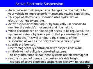
Active Electronic Suspension
Anactive electronic suspension changes the ride height for
your vehicle to improve performance and towing capabilities.
This type of electronic suspension uses hydraulics or
electromagnets to operate.
Active suspensions that adjust hydraulically use sensors to
monitor the vehicle’s movement and ride height.
When performance or ride height needs to be regulated, the
system activates a hydraulic pump that pressurizes the liquid
in the shocks. This will configure the stiffness of the
suspension as well as the height of the vehicle to your
specific preferences.
Electromagnetically controlled active suspensions work
similarly to hydraulically controlled systems.
The only difference is that these systems use electromagnet
motors instead of pumps to adjust a car’s ride height.
This type of active electronic suspension is known to respond
faster and use less power than hydraulics.
62.
Which type ofsuspension is good?
Both types of electronic suspensions can improve
performance
Looking for something to enhance your driving experience
during your commutes, consider an adaptive electronic
suspension
Ability to monitor the road and automatically adjust the stiffness of
the shocks will allow a smooth ride in most road conditions.
Looking to adjust vehicle height for towing or performance
purposes- consider an active electronic suspension kit
Allow to raise or lower your vehicle will help to tow more and ensure
a smooth ride