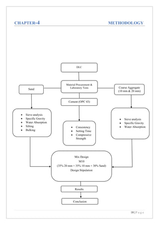
This document describes an internship report on the mix design of dry lean concrete. It was submitted as a requirement for a Bachelor of Technology degree in Civil Engineering. The internship was conducted under the guidance of faculty at CSIR- Central Road Research Institute and Madhav Institute of Technology & Science. The report includes an introduction to concrete and its materials, rigid pavements, dry lean concrete, and the methodology used for mix design testing and analysis during the internship. The objective was to study mix design of dry lean concrete and determine material properties in the hardened state.
This document summarizes a laboratory experiment conducted by civil engineering students at MUST to determine the crushing strength of a concrete aggregate sample. The experiment involved:
- Compacting an aggregate sample into a steel cylinder and subjecting it to a gradually increasing load in a compression testing machine according to British Standard 812.
- Sieving the crushed sample and calculating the aggregate crushing value (ACV) as the percentage of sample passing a 2.36mm sieve.
- The sample was found to have an ACV of 14.87%, indicating a "normal" quality aggregate suitable for use in road construction according to the standard.
Aggregates blending, blending aggregates by graphical method, concrete mix design, concrete technology, what is aggregates blending, what is blending, methods of blending, how to blend aggregates, civil engineering
A report on use of waste plastic in concreteVed Jangid
The document appears to be a project report submitted by five students for their Bachelor of Technology degree. It investigates using plastic waste as a partial replacement for coarse aggregates in concrete. The report includes sections on materials testing, mix design, casting of test specimens, testing of compressive and flexural strength, and analysis of results. The overall aim is to study the suitability of using plastic waste in concrete and determine the impact on properties like strength.
This document is a seminar report on using plastics in road construction, known as plastic roads. It discusses how plastic waste, which makes up around 5% of municipal solid waste, can be used as an additive in bitumen to construct roads. Using plastics in road construction provides benefits like reducing costs, improving properties of the bitumen such as strength and resistance to water, and providing an environmentally-friendly way to dispose of plastic waste. Previous studies have found that roads constructed with plastic waste perform better than conventional roads and are more durable. The objectives of the report are to coat aggregates with plastic waste materials and compare the properties of bitumen mixes with and without the plastic-coated aggregates.
The document describes the standard Proctor compaction test procedure. The test is used to determine the maximum dry density and optimum moisture content of soils. It involves compacting soil samples at incrementally increased moisture contents using a specified compaction method. A compaction curve is plotted showing the relationship between dry density and moisture content. The peak of the curve indicates the optimum moisture content and maximum dry density achieved for that soil. The test uses a cylindrical metal mold, rammer, balance, oven and other equipment to compact and analyze the soil samples according to steps that sieve, mix, compact and weigh the soil at different moistures.
The document provides information on different types of bitumen and bitumen modification. It discusses natural bitumen, artificial bitumen including straight run bitumen and blown bitumen. It also describes cut back bitumen, emulsions, and modified bitumens including crumb rubber modified bitumen, natural rubber modified bitumen, and polymer modified bitumen. The document lists the advantages of modified bitumens and guidelines for their use. It provides details on consistency tests, performance tests, and grades of different modified bitumens.
Project Report on Concrete Mix Design of Grade M35Gyan Prakash
This document provides a project report on the concrete mix design for grade M-35 concrete. It includes an introduction to concrete mix design objectives and considerations. It then describes the Indian Standard method for mix design in six steps: 1) selecting target compressive strength, 2) selecting water-cement ratio, 3) estimating air content, 4) selecting water content and fine-coarse aggregate ratio, 5) calculating cement content, and 6) calculating aggregate content. The report also includes test results for materials and mixes.
California bearing ratio test (CBR TEST)Ujas Patel
The California Bearing Ratio (CBR) test is used to determine the bearing capacity of soil subgrades and base course materials. The test involves measuring the penetration of a piston into a remolded soil sample under increasing loads. Loads are applied to penetrate the soil at 1.25 mm/min up to 12.5 mm. The CBR value is calculated by dividing the load measured from the soil sample at a given penetration by the standard load value for that penetration from a reference material with a CBR of 100%. Higher CBR values indicate soils with greater bearing capacity for supporting structures.
The document provides information about shear strength of soil. It defines shear strength and its components of cohesion and internal friction. It discusses Mohr's circle of stress and Mohr-Coulomb theory for shear strength. The types of soil are classified based on drainage conditions during shear testing. Common shear strength tests like direct shear test, triaxial test, unconfined compression test and vane shear test are also explained. Sample calculations for shear strength determination from test results are presented.
Project report on self compacting concreterajhoney
This project report summarizes research conducted on developing self-compacting concrete using industrial waste. A group of students conducted the research under the guidance of Prof. M. B. Kumthekar to fulfill requirements for a B.E. in Civil Engineering from Shivaji University, Kolhapur. The report documents the need for self-compacting concrete to improve construction efficiency and concrete quality. It describes tests conducted to utilize red mud and foundry waste sand as partial replacements for cement in self-compacting concrete mixtures and analyze the results.
This document describes the procedure for conducting a tensile test to determine the tensile splitting strength of a material according to BS 1881 standards. Specimens are placed between hardboard packing strips and steel loading pieces and loaded continuously in a testing machine until failure. The tensile splitting strength is calculated using the maximum load at failure, specimen dimensions, and material density.
This document discusses the split tensile strength test for concrete. It begins by explaining that the split tensile strength test is an indirect method for determining the tensile strength of concrete using cylindrical specimens. It then describes the procedure for the test, which involves placing a cylinder between loading plates and applying an increasing load until failure. The maximum load at failure is used to calculate the splitting tensile strength of the concrete. The document provides details on specimen preparation, curing, testing apparatus, and calculations.
1. The document discusses various destructive and non-destructive testing methods for measuring the properties of hardened concrete. 2. Destructive tests include cube tests to determine compressive strength and split-cylinder or flexural tests to determine tensile strength. 3. Non-destructive tests discussed are rebound hammer testing, ultrasonic pulse velocity testing, penetration resistance testing, pull-out testing, and using a profometer.
1) The document describes the process for Marshall stability test and mix design for bituminous concrete. Key steps include selecting aggregates based on strength and gradation, determining aggregate proportions, preparing specimens, and testing stability and flow.
2) Aggregate proportions are determined using an analytical method solving equations for the required gradation. Specimens are compacted and tested for stability (maximum load) and flow (deformation) at varying bitumen contents to determine the optimum mix.
3) Stability and flow values are measured using a Marshall test machine and calculations are done to determine density, voids, and other properties of the mix. The process is repeated to get the optimum bitumen content for the mix design.
The document discusses Superpave mix design, which is a performance-based method for designing asphalt concrete mixtures. Some key points:
- Superpave uses the gyratory compactor to simulate field compaction of mixtures, allowing for evaluation of density during the design process.
- The design process involves 4 steps: selecting materials based on traffic and climate conditions, designing the aggregate structure, determining the optimum asphalt binder content, and evaluating moisture susceptibility.
- Key evaluation points on the gyratory compaction curve are Ninitial, Ndesign, and Nmax, which control compactability, expected field density, and maximum allowed density.
- Design traffic level determines the number
Introduction on aggregate crushing value apparatusAbhishek Sagar
The principle mechanical properties required in road stones are
Satisfactory resistance to crushing under the roller during construction.
Adequate resistance to surface abrasions under traffic.
This document discusses materials used in highway construction. It outlines seven major materials: bituminous materials, soil, aggregates, Portland cement concrete, admixtures, pavement marking materials, and structural steel. For each material, it provides details on composition, properties, and relevant tests used for evaluation and quality control of the material. Key tests discussed include moisture content value, California bearing ratio, Los Angeles abrasion value, and specific gravity and water absorption.
Workability refers to the ease with which fresh concrete can be mixed, placed, compacted and finished. It is affected by factors like water content, mix proportions, aggregate size and shape, grading and surface texture. Increasing water content or using admixtures improves workability by acting as a lubricant between particles. Larger, rounded aggregates require less water than smaller, angular ones. Well-graded aggregates with minimal voids also increase workability. Workability can be measured using slump, compacting factor, flow, or Vee Bee tests.
The document describes the California Bearing Ratio (CBR) test procedure used to evaluate the strength of subgrade soils and base courses for pavement design. The CBR test involves compacting a soil sample and measuring the penetration resistance under a constant load over time. Higher CBR values indicate stronger soils that require less thick pavement sections. The document provides details on the test apparatus, sample preparation, soaking, loading and penetration measurements, and CBR calculations according to relevant Indian standards.
The unconfined compression test is a type of unconsolidated-undrained test used for clay specimens. It involves compressing a cylindrical clay sample axially without lateral confinement. The major principal stress is the axial stress, while the minor principal stresses are zero. This allows measuring the unconfined compressive strength, sensitivity, shear strength parameters, and cohesion of cohesive soils. The test procedure involves extruding and trimming a soil specimen, measuring it, and compressing it at a controlled strain rate between loading plates while recording the load and stress. Parameters are calculated based on the failure load and specimen dimensions.
Compressive Strength of Hydraulic Cement Mortar | Jameel AcademyJameel Academy
This document summarizes a test to determine the compressive strength of cement mortar cubes. Six cement mortar cubes were created and tested to failure. The compressive strength was calculated for each cube based on the failure load and cross-sectional area. The average compressive strength of the cubes was calculated to be 34.45 MPa. This result exceeds the standard requirement of 24 MPa or greater for cement mortar at 7 days. Therefore, the cement mortar tested was determined to be suitable for use in construction projects.
A presentation on concrete-Concrete TechnologyAbdul Majid
Concrete is a composite material made from cement, sand, gravel and water. It is one of the most commonly used building materials due to its advantages like durability, fire resistance and ability to be easily formed. Fresh concrete must be properly mixed, placed, consolidated and cured. Mixing ensures uniform distribution of ingredients while consolidation removes air pockets. Curing keeps concrete saturated to allow continued hydration and improve strength over time. Proper mixing, placing and curing are necessary to achieve the desired properties of hardened concrete.
This presentation includes in how many ways plastic can be used in soil stabilization. It covers how a waste material can be used without any additional increase in cost.
Use of Waste Materials As a replacement of Coarse Aggregate in Concrete MixNitin Yadav
The document discusses the use of waste materials in concrete. It outlines the objectives of reducing waste and finding alternative materials for construction. Three waste materials are examined: e-waste, rubber tire waste, and coconut shell waste. Their properties like water absorption and specific gravity are tested. Previous research on using these wastes in concrete is summarized. Experiments are described to determine properties of materials. A concrete mix design is provided with the goal of achieving 25MPa compressive strength. The document aims to explore sustainable and economical use of waste in construction materials.
The document provides information on bitumen mixes used for road construction. It discusses the constituents of bitumen mixes, which include aggregates, filler, and binders like bitumen. It describes different types of mixes like dense graded, stone matrix, and open graded mixes. It also covers characteristics of materials used in mixes and production methods for both hot and cold bitumen mixes. Cold mixes use bitumen emulsions and avoid heating of aggregates and binders.
This document discusses different methods for grading bituminous binders, including penetration grading, viscosity grading, and performance grading. Penetration grading uses the penetration test results at 25°C to specify grades. Viscosity grading specifies grades based on viscosity measurements at 60°C and 135°C. Performance grading assigns grades based on the temperature ranges where the binder is expected to perform satisfactorily against rutting, fatigue cracking, and low-temperature cracking. The document also covers specifications, advantages and disadvantages of each grading method, and definitions and measurement of viscosity and its importance in characterizing bitumen properties.
Lab and field eveluation of recycled cold mixNarendra Goud
This document is a dissertation report submitted in partial fulfillment of a Master of Technology degree in Transportation Engineering. It evaluates recycled cold mixes in the laboratory and field. The report was submitted by G. Narendra Goud under the guidance of Dr. Sunil Bose of CRRI-New Delhi and Shri Arun Gaur of MNIT-Jaipur. It includes an introduction, literature review, methodology, laboratory testing of mixes with emulsion and foamed bitumen, field testing through Benkelman Beam deflection and coring, and conclusions on the structural performance of foamed bitumen mixes.
An Investigation on Processing and Properties of Recycle Aggregate ConcreteMohammed Alauddin
This document is a thesis submitted by two students, Mohammad Belayet Hossain and Mohammed Alauddin, to the Department of Civil Engineering at Southern University Bangladesh in partial fulfillment of their Bachelor of Science degrees. The thesis investigates the processing and properties of recycled aggregate concrete. Laboratory experiments were conducted to test the compressive strength of concrete mixtures containing various percentages of recycled aggregates compared to fresh aggregates. 72 concrete cube specimens were tested at different curing periods up to 32 days. The results showed that concrete containing recycled aggregates achieved 65-84% of the target compressive strength of fresh aggregate concrete.
A design engineer is a person who may be involved in any of various engineering disciplines including civil, mechanical, electrical, chemical, textiles, aerospace, nuclear, manufacturing, systems, and structural /building/architectural. Design engineers tend to work on products and systems that involve adapting and using complex scientific and mathematical techniques. The emphasis tends to be on utilizing engineering physics and sciences to develop solutions for society.
The document is a geotechnical investigation report for a proposed check dam in Batase Danda, Kavre, Nepal. It details field investigations including three boreholes and standard penetration tests. Soil samples were collected and tested in the laboratory to determine properties. The report finds that subsurface soils consist of cohesionless silty sand and silty clay with low plasticity. Groundwater was encountered at shallow depths. Bearing capacity analysis was performed and allowable bearing pressures were calculated based on standard methods. Recommendations for dam foundation type and construction materials were provided based on the investigation results.
This report details a study on the fresh and hardened properties of normal strength self-compacting concrete (SCC). Mix designs were developed and tested to meet fresh concrete requirements for flowability, passing ability, and segregation resistance. The finalized mix was then evaluated for hardened properties like compressive, tensile, and flexural strength along with stress-strain behavior up to 14 days. The results provide insight into developing reliable normal strength SCC mixes and understanding their fresh and hardened characteristic properties.
This document provides details about a residential building project constructed by Raunak Group in Mumbai. It includes a 13 storey building with 93 flats of 3 BHK configuration. The building uses shallow foundations consisting of individual, strip and raft foundations due to the soil conditions. The superstructure is constructed with reinforced concrete using materials like cement, fine and coarse aggregates, and water. Construction techniques like brick masonry and plastering are also discussed.
A Review Paper on Experimental Study of Demolished Concrete use in Rigid Pave...ijtsrd
Today construction is increasing very fast rate and due to increase in construction concrete waste is produced in large amount. So for dispose of this waste large amount of land fill is required and also it impacts the environment condition. In this study we use this demolished waste concrete by replacing normal fresh aggregate. Demolished aggregate are used in the mixture of concrete in the different proportions. Pardeep Singh | Mr. Magandeep Bishnoi ""A Review Paper on Experimental Study of Demolished Concrete use in Rigid Pavement Construction"" Published in International Journal of Trend in Scientific Research and Development (ijtsrd), ISSN: 2456-6470, Volume-3 | Issue-4 , June 2019, URL: https://www.ijtsrd.com/papers/ijtsrd24053.pdf
Paper URL: https://www.ijtsrd.com/engineering/civil-engineering/24053/a-review-paper-on-experimental-study-of-demolished-concrete-use-in-rigid-pavement-construction/pardeep-singh
This document provides a resume for Dr. Ashok Kumar Gupta. It includes his personal details like name, date of birth, qualifications, experience, research interests and publications. Some key points:
- Dr. Gupta is a Professor and Head of the Department of Civil Engineering at Jaypee University of Information Technology.
- He holds a Ph.D. in Civil Engineering from IIT Delhi and has over 27 years of teaching experience.
- His research interests include testing and modeling of geotechnical materials, finite element methods, and rock mechanics.
- He has supervised several Ph.D. and Masters students and published over 20 papers in journals and conferences.
- Dr. Gupta
MAGA Engineering is a leading construction company in Sri Lanka that has been in operation since 1984. The report discusses the trainee's 3-month in-plant training experience working on the NSBM Green University Town project in Pitipana, which MAGA Engineering is constructing. During the training period, the trainee engaged in various construction activities like formwork, reinforcement, concreting, surveying, and attended seminars to learn and gain experience.
This capstone project investigates sustainable soil stabilization methods using natural fibers available in Fiji. A group of civil engineering students will conduct model tests to study the effects of coconut husk and bamboo fibers on soil strength. They will collect soil data from field sites, perform laboratory experiments, and use GeoStudio and FLAC 3D software to analyze results. The project aims to develop cost-effective alternatives to reinforcement steel for retaining walls and pavements. Expected outcomes include explaining stabilization mechanisms, validating numerical models, presenting findings, and concluding on fiber-reinforced soil performance.
This document provides details about an industrial case study report on the construction of a residential building project called Ramky One Kosmos in Hyderabad, India. The report describes the project, including structural details, materials used, construction methods, human resource management, safety practices, and the author's work experience during their training period. The training helped the author understand the practical differences between construction site work and theoretical classroom knowledge.
Design & Fabrication of a low cost spin coaterSaurabh Pandey
Spin Coating is basically a procedure which is used to deposit uniform thin films to any flat surface of work piece. Usually a small amount of coating material is applied on the centre of the work piece’s surface when the disk is spinning at very low speed. Here in this process we are using the basic principle of centrifugal force. This is applied due to the spinning of Disk.
Design engineers may work in a team along with other designers to create the drawings necessary for prototyping and production, or in the case of buildings, for construction. However, with the advent of CAD and solid modeling software, the design engineers may create the drawings themselves, or perhaps with the help of many corporate service providers.
SOIL EXPLORATION AND GEOTECHNICAL DESIGN OF A FOUNDATIONIRJET Journal
This document summarizes a soil exploration and geotechnical design study for the foundation of a proposed multi-story commercial building. It first describes conducting a site investigation that included borehole drilling, soil sampling, and laboratory testing to characterize the soil properties. The results indicated the soil at shallow depths was unsuitable to support the building loads with a shallow foundation. Therefore, a pile foundation was selected, with the design involving calculating the load capacity of piles based on their end bearing into stronger soil or rock layers at depth. The document provides details of the site location, soil conditions, shallow foundation capacity calculations, and pile foundation design methodology.
The document describes a summer training project report on soil and concrete testing conducted at a site in New Delhi. It provides details of various tests performed on soil samples collected from the site, including sieve analysis, mechanical analysis, liquid limit, plastic limit, shrinkage limit, consolidation, permeability and specific gravity tests. It also describes some basic cement tests conducted like fineness, setting time, soundness and consistency tests. The trainees gained hands-on experience of actual field and lab procedures under expert guidance during their 6-week summer training project.
Report on Industrial training at BRPNNL PatnaNarayan Gupta
This document appears to be a project report submitted by three students - Akhilesh Rajput, Narayan Gupta, and Mahendra Kumar - for their Bachelor of Technology degree. The report details their four month vocational training undertaking the construction of two flyovers in Patna, India - one connecting R-Block junction and another connecting Karbigahiya. It provides an overview of the project, acknowledges those involved in the training, and outlines the contents of the report which will explain the planning, execution, materials, testing, and safety aspects of the flyover construction.
Compressive strength of concrete with fly ash, nanosilica and recycled aggregateeSAT Journals
Abstract In this study, concrete mix was prepared using recycled aggregates (RA) which were retrieved from demolished concrete blocks. Pozzolanic materials like fly ash (FA) and nanosilica (NS) were used as partial replacement of cement by weight in varying percentages i.e. 10%, 20% 30% and 2%, 3%, 4% respectively. The experimental work was focused on investigating the effect of nanosilica and fly ash on fresh properties and compressive strength of recycled aggregate concrete (RAC). To examine the fresh properties of concrete, slump test was performed for workability requirements. It was observed from experimental results that with the increase in percentage of recycled aggregates in concrete, compressive strength decreases but workability was not affected up to 50% variation of recycled aggregates. Results showed that with the addition of nanosilica compressive strength of concrete was increased but workability was decreased with the increase in percentage of nanosilica. The use of fly ash in addition to nanosilica (30% RA+3% NS + 10% Fly Ash) improved both the workability and compressive strength of recycled aggregate concrete (RAC). Keywords: Compressive strength, Recycled aggregates (RA), Nanosilica (NS), Fly Ash (FA), Recycled aggregate concrete (RAC).
Study of Fiber Reinforced Polymer Materials in Reinforced Concrete Structures...Girish Singh
Around the world we are having several upcoming projects near the coast line so the study is needed to understand the effect on cost when we use FRP in the structure because FRP is a costly material compare to steel which may or may not increase the structure overall cost.
It will may or may not increase the structure cost because if we use FRP in a structure then we can avoid the problem that we face in a structure caused due to corrosion which reduce strength of the structure, foundation loosing plaster from the surface of the reinforced section due to expansion caused due to rusting as well as in building envelopes.
The objectives of this seminar report are to study about FRP Manufacturing and its properties, study about the various applications of FRP, design and analyze a FRP member, Finite element analysis of a simple beam using FRP as a reinforcement, role of FRP in the sustainable world, to find out the cost benefit of the elements used in a corrosive environment structure which can be replaced by the FRP.
This study will cover all the forms of FRP that can be used in a building and give a brief about FRP rebars its properties, design, analysis, uses and the effect on cost of a build during construction as well as the cost analysis of the structure.
This study will give an idea on the advantage of FRP over steel when we are using FRP in a corrosive environment like coast line and it will give an initial idea to the designer about the advantage and disadvantage of FRP over steel.
In the final part of this seminar report analysis results are used to give a base that FRP can sustain in structure as FRP reinforced bar and an example of a LCC is also used to give a satisfactory conclusion and on the final page the summery of the seminar is present.
most final report of industrial training for collegeindrajeet kumar
The topography survey provides essential information for planning and designing the highway project which includes:
- Establishing temporary and permanent benchmarks along the alignment to record elevations
- Mapping the existing road, structures, utilities, buildings, trees etc. within the right of way through coordinate and elevation recording
- Developing a base map showing all relevant existing features to aid the design process
- Transferring survey data to AutoCAD software for detailed drawing preparation
The survey facilitates design of proposed road geometry, structures, pavement layers and right of way requirements.
This document is a project report submitted by Maung Wai Hin Tun to Curtin University as part of the requirements for a Bachelor of Engineering degree. The project examines the properties of hydrated cement paste containing microsilica and nano iron oxide particles. Seven mixtures were designed with different content percentages of nano and micro particles. Tests performed on the mixtures included compressive strength testing at various ages, X-ray diffraction, scanning electron microscopy, setting time tests, and nano-indentation to determine properties such as strength, microstructure, setting behaviors, elastic modulus and hardness. Results from the tests revealed that mixtures with 2-3% nano iron oxide provided higher strength, durability, initial setting and stiffness, while 5% nano iron oxide
Use PyCharm for remote debugging of WSL on a Windo cf5c162d672e4e58b4dde5d797...shadow0702a
This document serves as a comprehensive step-by-step guide on how to effectively use PyCharm for remote debugging of the Windows Subsystem for Linux (WSL) on a local Windows machine. It meticulously outlines several critical steps in the process, starting with the crucial task of enabling permissions, followed by the installation and configuration of WSL.
The guide then proceeds to explain how to set up the SSH service within the WSL environment, an integral part of the process. Alongside this, it also provides detailed instructions on how to modify the inbound rules of the Windows firewall to facilitate the process, ensuring that there are no connectivity issues that could potentially hinder the debugging process.
The document further emphasizes on the importance of checking the connection between the Windows and WSL environments, providing instructions on how to ensure that the connection is optimal and ready for remote debugging.
It also offers an in-depth guide on how to configure the WSL interpreter and files within the PyCharm environment. This is essential for ensuring that the debugging process is set up correctly and that the program can be run effectively within the WSL terminal.
Additionally, the document provides guidance on how to set up breakpoints for debugging, a fundamental aspect of the debugging process which allows the developer to stop the execution of their code at certain points and inspect their program at those stages.
Finally, the document concludes by providing a link to a reference blog. This blog offers additional information and guidance on configuring the remote Python interpreter in PyCharm, providing the reader with a well-rounded understanding of the process.
Advanced control scheme of doubly fed induction generator for wind turbine us...IJECEIAES
This paper describes a speed control device for generating electrical energy on an electricity network based on the doubly fed induction generator (DFIG) used for wind power conversion systems. At first, a double-fed induction generator model was constructed. A control law is formulated to govern the flow of energy between the stator of a DFIG and the energy network using three types of controllers: proportional integral (PI), sliding mode controller (SMC) and second order sliding mode controller (SOSMC). Their different results in terms of power reference tracking, reaction to unexpected speed fluctuations, sensitivity to perturbations, and resilience against machine parameter alterations are compared. MATLAB/Simulink was used to conduct the simulations for the preceding study. Multiple simulations have shown very satisfying results, and the investigations demonstrate the efficacy and power-enhancing capabilities of the suggested control system.
Embedded machine learning-based road conditions and driving behavior monitoringIJECEIAES
Car accident rates have increased in recent years, resulting in losses in human lives, properties, and other financial costs. An embedded machine learning-based system is developed to address this critical issue. The system can monitor road conditions, detect driving patterns, and identify aggressive driving behaviors. The system is based on neural networks trained on a comprehensive dataset of driving events, driving styles, and road conditions. The system effectively detects potential risks and helps mitigate the frequency and impact of accidents. The primary goal is to ensure the safety of drivers and vehicles. Collecting data involved gathering information on three key road events: normal street and normal drive, speed bumps, circular yellow speed bumps, and three aggressive driving actions: sudden start, sudden stop, and sudden entry. The gathered data is processed and analyzed using a machine learning system designed for limited power and memory devices. The developed system resulted in 91.9% accuracy, 93.6% precision, and 92% recall. The achieved inference time on an Arduino Nano 33 BLE Sense with a 32-bit CPU running at 64 MHz is 34 ms and requires 2.6 kB peak RAM and 139.9 kB program flash memory, making it suitable for resource-constrained embedded systems.
Design and optimization of ion propulsion dronebjmsejournal
Electric propulsion technology is widely used in many kinds of vehicles in recent years, and aircrafts are no exception. Technically, UAVs are electrically propelled but tend to produce a significant amount of noise and vibrations. Ion propulsion technology for drones is a potential solution to this problem. Ion propulsion technology is proven to be feasible in the earth’s atmosphere. The study presented in this article shows the design of EHD thrusters and power supply for ion propulsion drones along with performance optimization of high-voltage power supply for endurance in earth’s atmosphere.
Batteries -Introduction – Types of Batteries – discharging and charging of battery - characteristics of battery –battery rating- various tests on battery- – Primary battery: silver button cell- Secondary battery :Ni-Cd battery-modern battery: lithium ion battery-maintenance of batteries-choices of batteries for electric vehicle applications.
Fuel Cells: Introduction- importance and classification of fuel cells - description, principle, components, applications of fuel cells: H2-O2 fuel cell, alkaline fuel cell, molten carbonate fuel cell and direct methanol fuel cells.
Applications of artificial Intelligence in Mechanical Engineering.pdfAtif Razi
Historically, mechanical engineering has relied heavily on human expertise and empirical methods to solve complex problems. With the introduction of computer-aided design (CAD) and finite element analysis (FEA), the field took its first steps towards digitization. These tools allowed engineers to simulate and analyze mechanical systems with greater accuracy and efficiency. However, the sheer volume of data generated by modern engineering systems and the increasing complexity of these systems have necessitated more advanced analytical tools, paving the way for AI.
AI offers the capability to process vast amounts of data, identify patterns, and make predictions with a level of speed and accuracy unattainable by traditional methods. This has profound implications for mechanical engineering, enabling more efficient design processes, predictive maintenance strategies, and optimized manufacturing operations. AI-driven tools can learn from historical data, adapt to new information, and continuously improve their performance, making them invaluable in tackling the multifaceted challenges of modern mechanical engineering.
Applications of artificial Intelligence in Mechanical Engineering.pdf
A Project Report.pdf
1. 1 | P a g e
An
Internship Report
On
Mix Design of Dry Lean Concrete
In partial fulfilment of the requirement for the award of degree of
BACHELOR OF TECHNOLOGY
IN
CIVIL ENGINEERING
Submitted by
RAJ PRATAP SINGH KIRAR
(0901CE191088)
Under the guidance of
Mr. Dinesh Ganvir Mr. Abhilash Shukla
HOD, Rigid Pavement Division Asst. Professor
CSIR- Central Road Research Institute Department of Civil Engineering
New-Delhi MITS, Gwalior
Rigid Pavement Division Department of Civil Engineering
CSIR- Central Road Research Institute Madhav Institute of Technology & Science
Mathura Road, New-Delhi 110020 Race-Course Road, Gwalior, (M.P.) 474005
(Session: June-July, 2022) (Session: June-July, 2022)
2. 2 | P a g e
I hereby certify that the Internship report entitled Summer Internship III (Mix
Design of Dry Lean Concrete) which is being submitted in Civil Engineering
Department is a record of my own work carried out under the supervision and
guidance of Mr. Dinesh Ganvir, HOD, RIGID PAVEMENT DIVISION, CRRI,
Department of Civil Engineering, Madhav Institute of Technology & Science,
Gwalior.
All information in this document has been obtained and presented in accordance with
academic rules and ethical conduct. I have fully cited and referenced all material and
results that are not original to this work.
To the best of my knowledge the material presented in this report has not been
submitted to any other place (i.e., institute, university, organization) as thesis/report
except the industry, where this work has been carried out.
Date: RAJ PRATAP SINGH KIRAR
Place: Gwalior 0901CE191088
This is to certify that the above statement made by the candidate is correct to the best
of my knowledge and belief.
Guided by
Mr. Dinesh Ganvir Mr. Abhilash Shukla
HOD, Rigid Pavement Division Asst. Professor
CSIR- Central Road Research Institute Department of Civil Engineering
New-Delhi MITS, Gwalior
Approved by
Dr. M.K Trivedi
Prof. & Head
Department of Civil Engineering
MITS, Gwalior
MadhavInstituteof Technology& Science, Gwalior(M.P.)
(A Govt. AidedUGC AutonomousInstitute& NAAC Accredited,Estd. in 1957, Affiliated
.
to RGPVBhopal)
CANDIDATE’S DECLARATION
3. 3 | P a g e
I would like to express my sincere appreciation to my supervisor Mr.
Dinesh Ganvir for his guidance, encouragement, and support throughout the
course of this work. It was an invaluable learning experience for me to be one
of their students. From them I have gained not only extensive knowledge, but
also a careful research attitude.
I am also thankful to Mr. Babulal for his cooperation with me in
facilitating the infrastructure and lab facility during my work.
I am highly indebted to Dr R.K. Pandit, Director M.I.T.S., Gwalior
(M.P.) for the facilities provided to accomplish this internship.
I would like to thank Dr M.K. Trivedi, Head department of Civil
engineering, M.I.T.S., Gwalior (M.P.) for his constructive criticism
throughout my internship.
I would like to thank Mr. Abhilash Shukla, internship coordinator
Department of Civil Engineering for their support and advices to get and
complete internship in above said organization. I am extremely great full to
my department staff members and friends who helped me in successful
completion of this internship.
Date: RAJ PRATAP SINGH KIRAR
Place: Gwalior (M.P.) 0901CE191088
ACKNOWLEDGEMENT
MadhavInstituteof Technology& Science,Gwalior(M.P.)
(A Govt. AidedUGC AutonomousInstitute& NAACAccredited,Estd.in 1957, Affiliated
.
to RGPVBhopal)
5. 5 | P a g e
Structure of the report
I have started my report with certificate, acknowledgement and abstract. The abstract
represents a 1-page summary of our project highlighting its salient features.
The report comprises of 5 chapters, including:
Chapter 1 is “Introduction” It states the basic knowledge about the history of India's
concrete road scheme, and road infrastructure of India, describes brief introduction
about the material, summarizes the need for study and objectives of the study.
Chapter 2 is “Rigid Pavement" It states the basic introduction of rigid pavement, the
advantages of rigid pavement, and the layers of rigid pavement. the comparison of
rigid pavement and flexible pavement, and the importance of rigid pavement.
Chapter 3 is “Dry Lean Concrete" It states the basic introduction of dry lean
concrete, the significance, advantages, constituent materials used in DLC design as per
IRC: SP:49.
Chapter 4 is “Methodology" It states dry lean concrete mixes and specimen
preparation, the properties of the material used in our mix design and the Design
stipulation. The trial mixes of dry lean concrete and its concrete compressive strength.
Chapter 5 is “Result and Conclusion" In this, the result of the 7-day testing report
data, Conclusion for future study and the result of work in short words, and references
for the reference material which we used in this report.
6. 6 | P a g e
Abstract
I carried out my internship at central road research institute (CRRI-CSIR) New Delhi
institution act for the research and project work in the domain of civil engineering and
it offers internship opportunities to the students of other institution in research –based
projects etc. Internship is the opportunity to relate what has been covered during classes
and studies and what is applicable in a practical/realistic environment.
I have assigned to Rigid pavement department, where I had done my internship in the
given domain. During my internship period I have learnt about the Mix Design of Dry
Lean Concrete, after the theoretical base understanding, I have worked on the testing of
properties of cement, sand and aggregate, also did the physical lab work. Through all
these workings I gained the knowledge that how it can help in the realistic environment
and contribute in the construction works.
The objective of our project was to study the Mix Design of Dry lean Concrete and the
determination of various properties of materials of concrete in the hardened state. we
have drawn the curve of moisture content concerning maximum dry density that had
given us an idea about the optimum moisture content at which maximum compressive
strength of concrete had to be achieved.
7. 7 | P a g e
Table of Contents
CHAPTER-1 INTRODUCTION ...................................................................... 9
1.1 HISTORY OF CONCRETE ........................................................................................................................................ 9
1.2 ROAD INFRASTRUCTURE....................................................................................................................................... 9
1.3 CEMENT................................................................................................................................................................ 9
1.4 SAND.................................................................................................................................................................... 9
1.5 AGGREGATE ....................................................................................................................................................... 10
1.6 CONCRETE.......................................................................................................................................................... 10
1.7 OBJECTIVE OF STUDY ......................................................................................................................................... 10
CHAPTER-2 RIGID PAYMENTS..................................................................... 11
1.8 INTRODUCTION................................................................................................................................................... 11
1.9 ADVANTAGES OF RIGID PAVEMENTS................................................................................................................... 11
1.10 LAYERS OF RIGID PAVEMENTS............................................................................................................................ 12
1.11 COMPARISON OF RIGID AND FLEXIBLE PAVEMENTS ............................................................................................ 12
1.12................................................................................................................................................................................. 14
1.13 IMPORTANCE OF RIGID PAVEMENTS.................................................................................................................... 14
CHAPTER-3 DRY LEAN CONCRETE..................................................................... 15
1.15 INTRODUCTION................................................................................................................................................... 15
1.16 SIGNIFICANCE..................................................................................................................................................... 15
1.17 ADVANTAGES OF DRY LEAN CONCRETE.............................................................................................................. 15
1.18 CONSTITUENT MATERIALS.................................................................................................................................. 16
1.18.1 Cement...................................................................................................................................................... 16
1.18.2 Aggregate ................................................................................................................................................. 16
1.18.3 Water ........................................................................................................................................................ 16
CHAPTER-4 METHODOLOGY ..................................................................... 18
1.19 PROPERTIES OF MATERIALS ................................................................................................................................ 19
1.19.1 Cement: .................................................................................................................................................... 19
1.19.2 Tests on Cements ...................................................................................................................................... 20
1.19.3 Aggregates:............................................................................................................................................... 22
1.19.4 Tests on Aggregate ................................................................................................................................... 22
1.19.5 Sand:......................................................................................................................................................... 26
1.19.6 Tests on Sand............................................................................................................................................ 26
1.19.7 All in Aggregate: ...................................................................................................................................... 27
1.20 DESIGN STIPULATION.......................................................................................................................................... 28
1.21 TRIAL MIXES....................................................................................................................................................... 29
1.22 DRY LEAN CONCRETE MIXES AND SPECIMEN PREPARATION................................................................................ 29
CHAPTER-5 RESULT AND CONCLUSION .................................................................... 30
1.23 RESULT............................................................................................................................................................... 30
1.24 MIX DESIGN AS PER IRC:SP:49-2014 ................................................................................................................... 31
1.25 CONCLUSION ................................................................................................ ERROR! BOOKMARK NOT DEFINED.
REFERENCES:................................................................................................................................................................... 32
8. 8 | P a g e
List of Figures
FIGURE 1 RIGID PAVEMENT .............................................................................................................................................. 11
FIGURE 2 LAYERS OF RIGID PAVEMENTS......................................................................................................................... 12
FIGURE 3 COMPARISON OF RIGID AND FLEXIBLE PAVEMENTS ....................................................................................... 14
FIGURE 4 DRY LEAN CONCRETE....................................................................................................................................... 15
FIGURE 5 ORDINARY PORTLAND CEMENT ....................................................................................................................... 19
FIGURE 6 TEST FOR CONSISTENCY OF CEMENT............................................................................................................... 20
FIGURE 7 CUBE AFTER COMPRESSION TEST..................................................................................................................... 21
FIGURE 8 GRADATION GRAPH.......................................................................................................................................... 28
FIGURE 9 CASTED CONCRETE CUBES................................................................................................................................ 29
FIGURE 10 TESTED ON UTM............................................................................................................................................. 29
FIGURE 11 CURVE B/W DD AND MC................................................................................................................................. 30
List of Tables
TABLE 1 COMPARISON OF RIGID AND FLEXIBLE PAVEMENTS ........................................................................................ 12
TABLE 2 AGGREGATE GRADATION FOR DLC................................................................................................................... 16
TABLE 3 CEMENT PROPERTIES ......................................................................................................................................... 19
TABLE 4 RESULT OF CONSISTENCY OF CEMENT.............................................................................................................. 20
TABLE 5 COMPRESSIVE STRENGTH OF CEMENT .............................................................................................................. 22
TABLE 6 SIEVE ANALYSIS OF 20 MM AGGREGATE ........................................................................................................... 23
TABLE 7 SIEVE ANALYSIS OF 10 MM AGGREGATE ........................................................................................................... 24
TABLE 8 RESULTS OF SPECIFIC GRAVITY AND WATER ABSORPTION TEST ON 20 MM AGGREGATES............................ 25
TABLE 9 RESULTS OF SPECIFIC GRAVITY AND WATER ABSORPTION TEST ON 10 MM AGGREGATE ............................ 25
TABLE 10 SIEVE ANALYSIS OF SAND................................................................................................................................. 26
TABLE 11 SPECIFIC GRAVITY AND WATER ABSORPTION OF SAND................................................................................. 27
TABLE 12 GRADATION AS PER IRC:SP:49....................................................................................................................... 27
TABLE 13 DESIGN STIPULATION ....................................................................................................................................... 28
9. 9 | P a g e
CHAPTER-1 INTRODUCTION
HISTORY OF CONCRETE
Concrete pavements have been used for many years. However, the recent advancements in concrete
paving technology have led to better transportation facilities. Here we shall discuss the history of
concrete pavements and how they evolved from time to time. There is a disadvantage of concrete
pavements, which is a high initial cost. However, concrete pavement proves to be more durable in the
long run. Concrete pavements are generally used in almost all developed countries, including some
developing countries.
The first concrete road in India was built just over a hundred years ago; in early 1914 to be precise, in
the city then known as Madras (now Chennai). It was constructed outside the Municipality office, and
the builder had guaranteed that it would last for at least 10 years.
In the past, gravel mad faces, cobbles and granite Sens were extensively used, he these surfaces have
mostly been replaced by asphalt or concrete land on a compacted huse course. Road faces are
frequently marked to guide traffic. Today, permeable paving methods are beginning to be used for
low-impact roadways and walkways.
ROAD INFRASTRUCTURE
Road infrastructure is an essential component of economic development. Roads serve an important
role in the transportation of goods and people, as well as interconnecting to airports, trains, & ports
etc. Roads connect remote areas, allowing backward regions accessibility to commerce and
investment, leading in the country's aggressive growth. The expansion of a roadway network is a
subject of concern from this perspective.
CEMENT
Cement is generally used as a binding material, which sets well and hardens under the effect of water
and gives the desired strength. The purpose of each grade of cement is same that is to bind the materials
like fine and coarse aggregate used in concrete. The origin of hydraulic cements goes back to ancient
Greece and Rome. The materials used were lime and a volcanic ash that slowly reacted with it in the
presence of water to form a hard mass.
There are four stages in the manufacture of Portland cement:
• Crushing and grinding the raw materials.
• Mixing the materials in the correct proportions.
• Burning the prepared mix in a kiln.
• Grinding the burned product.
India is the second-largest producer of cement after China. India's overall cement production
accounted for 294.4 million tonnes (MT) in FY21 and 329 million tonnes (MT) in FY20.
SAND
Sand is a naturally occurring granular material composed of finely ground rock and mineral particles.
It is a popular manufacturing material used across a broad spectrum of construction, glass, and
10. 10 | P a g e
transportation industries. Natural sand occurring at river side due to erosion of rocks, river water and
other reasons, is majorly used as fine aggregate in concrete. Natural sand has an ideal shape to be used
as fine aggregate in concrete. The particles of natural sand are well-rounded and are usually nearly
spherical. Spherical particles decrease the percentage of voids within the concrete mixture so no
additional paste is required to fill these voids. Well-shaped natural sands are ideal for workability of
mixtures.
AGGREGATE
Aggregate is a component of composite materials such as concrete and asphalt concrete. Aggregate
comprises large chunks of material in a composite, commonly coarse gravel or crushed rocks and fine
materials. Aggregate comes in two types:
Fine aggregate – normally consists of sand, crushed stone or crushed slag screenings; most particles
pass through a 3/8-inch sieve.
Coarse aggregate – consists of gravel (pebbles), fragments of broken stone, slag and other coarse
substances; particles range between 3/8 and 1.5 inches in diameter
CONCRETE
Concrete is a composite material, consisting mainly of Portland cement, water and aggregate (gravel,
sand or rock). When these materials are mixed together, they form a workable paste which then
gradually hardens over time. Concrete is the second-most-used substance in the world after water
and is the most widely used building material. Its usage worldwide, ton for ton, is twice that of steel,
wood, plastics, and aluminium combined.
Concrete consists of majorly cement, fine aggregate, coarse aggregate and water. Concrete once cast
and cured does not require any major maintenance and can hold up against any weather condition,
Concrete can be shaped in various forms when freshly mixed, which makes concrete a crucial
material for construction and civil engineering work. Concrete is a non-combustible or decaying
material that makes it inert material that doesn’t burn, decay or rot.
Types Of Concrete You Should Know About:
• Reinforced Concrete.
• Lightweight Concrete.
• High-Strength Concrete.
• High-Performance Concrete.
• Precast Concrete.
OBJECTIVE OF STUDY
The objective of our project is to study the Mix Design of Dry lean Concrete and the determination of
various properties of materials of concrete in the hardened state. we will draw the curve of moisture
content concerning maximum dry density which will give us an idea about the optimum moisture
content at which maximum compressive strength of concrete to be achieved.
11. 11 | P a g e
CHAPTER-2 RIGID PAYMENTS
INTRODUCTION
Rigid pavements are constructed of Portland cement concrete slabs resting on a prepared subbase of
granular material or directly on a granular subgrade. Load is transmitted through the slabs to the
underlying subgrade by flexure of the slabs. As the name implies, rigid pavements are rigid i.e., they
do not flex much under loading like flexible pavements. They are constructed using cement concrete.
In this case, the load carrying capacity is mainly due to the rigidity ad high modulus of elasticity of the
slab (slab action).
Rigid pavements are named so because of the high flexural rigidity of the concrete slab and hence the
pavement structure deflects very little under loading due to the high modulus of elasticity of their
surface course. In the design of a rigid pavement, the flexural strength of concrete is the major factor
and not the strength of subgrade.
The plain cement concrete slabs are expected to take up about 45kg/cm2 flexural stress. The rigid
pavement has a slab action and is capable of transmitting the wheel load stresses through a wider area
below.
ADVANTAGES OF RIGID PAVEMENTS
The design of rigid pavement is based on providing a structural cement concrete slab of sufficient
strength to resists the loads from traffic. The rigid pavement has rigidity and high modulus of
elasticity to distribute the load over a relatively wide area of soil.
The advantages of Rigid Pavements are:
• The Low maintenance and operation cost.
• Higher life span.
• It has high flexural strength.
• It has good resistance to petroleum products, oils, and chemicals.
• More environment-friendly than flexible pavement.
• It distributes loads in a wider area and can bear a large amount of load due to slab action.
Figure 1 Rigid Pavement
12. 12 | P a g e
LAYERS OF RIGID PAVEMENTS
The structure of a rigid pavement consists following layers.
• Concrete slab or surface course.
• Granular base or stabilized base course.
• Granular subbase or stabilized subbase course.
• Frost protection layer.
• Subgrade soil.
COMPARISON OF RIGID AND FLEXIBLE PAVEMENTS
Table 1 Comparison of Rigid and Flexible Pavements
Sr.
No.
Flexible Pavement Rigid Pavement
1. The earthen, gravel, water bound
macadam and bituminous roads are
known as flexible pavement.
Cement concrete roads are known as rigid pavement.
2. In flexible pavement, the top surface takes
to shape of the sub surface soil.
The rigid pavement has more stiffness and capacity to
bridge over loose soil pockets in the sub grade.
Figure 2 Layers of Rigid Pavements
13. 13 | P a g e
3. Due to more stiffness and thickness, there
are no ups and downs on concrete roads.
Due to flexibility, there are ups and downs on WBM
roads and bituminous roads, but there are no ups and
down in case of rigid pavement.
4. Design principle based on load
distribution characteristics of the
components.
Designed and analysed by using the elastic theory.
5. Granular material is used in flexible
pavement.
Cement concrete either plain reinforced or pre stressed
concrete is used in rigid pavement.
6. It has low or negligible flexural strength. It is associated with rigidity or flexural strength or slab
action so the load is distributed over a wide area of
sub-grade soil.
7. Elastic deformation due to normal
loading.
Acts as a beam or cantilever for normal loading.
8. Local depression due to excessive
loading.
Causes cracks due to excessive loading.
9. Transmits vertical and compressive
stresses to the lower layer.
Tensile stress and temperature stress increase.
10. It is constructed in the number of layers in
design practice.
It is laid in slabs with steel reinforcement in design
practice.
11. Road can be used for traffic within 24
hours.
Road cannot used until 14 days of curing.
12. Rolling f surfacing is required. Rolling of the surfacing is not required.
13. Initial cost is low. Initial cost is high.
14. Life span is short. Life span is long.
14. 14 | P a g e
15. Their thickness is more. Their thickness is less.
IMPORTANCE OF RIGID PAVEMENTS
The largest advantage of using rigid pavement is its durability and ability to hold a shape against traffic
and difficult environmental conditions. Although concrete pavement is less expensive but has less
maintenance and good design life.
Figure 3 Comparison of Rigid and Flexible pavements
15. 15 | P a g e
CHAPTER-3 DRY LEAN CONCRETE
INTRODUCTION
Dry Lean Concrete (DLC) is an important part of modern rigid pavement. It is a plain concrete with a
large ratio of aggregate to cement than conventional concrete and generally used as a base/sub base of
rigid pavement. DRY LEAN CONCRETE is cement concrete with low slump as well as low cement
which is being laid as a first layer for rigid pavement over sub-base (GSB), rolled & compacted by
mechanical means.
Dry Lean Concrete is a mixture in which the amount of cement is less than the amount of liquid that
is present in the layers. This makes it ideal as a base layer on which other types of concrete are placed
on top. It is good for a flat surface on uneven or dirty terrain.
DLC is mostly manufactured with ordinary Portland cement as per Indian Road Congress specification
IRC SP-49: 2014. This specification (IRC SP-49, 2014) advocates the use of other cement such as
Portland pozzolana cement (PPC), Portland slag cement (PSC) also in the manufacture of DLC. It sets
a requirement of 7 MPa compressive strength of DLC at 7- day and minimum ordinary Portland cement
(OPC) content of 140 kg/m3 is prescribed for it.
SIGNIFICANCE
Dry Lean Concrete is an important part of the modern rigid floor. It is smooth concrete with a large
proportion of aggregate in relation to cement than conventional concrete and is generally used as a
sub/ base for PQC. The dry lean concrete is compacted using a 10 to 12T vibrating roller in the field.
Dry Lean Concrete (DLC) Provides an even and more robust base to the Pavement Quality Concrete
(PQC). It provides resistance to the deformation of concrete pavement. DLC gives greatly improved
load transfer efficiency at the PQC joints.
ADVANTAGES OF DRY LEAN CONCRETE
• Provides even and stronger support to the PQC.
• Provides even and stronger support to the hard floor.
• It has a high resistance to deformation.
• It has excellent improved load transfer efficiency at the joints.
• Helps in all weather conditions.
• There is a final reduction in the depth of the slab due to the DLC as a base layer.
Figure 4 Dry Lean Concrete
16. 16 | P a g e
CONSTITUENT MATERIALS
Cement
Any of the following types of cement capable of achieving the design strength may be used with
prior approval of the Engineer-in-Charge subject to the condition that satisfy the Specifications in
respective IS codes. The minimum 28-day compressive strength of cement should not be less than 43
MPa.
1. Ordinary Portland Cement, 43 Grade & 53 Grade, IS:269
2. Portland-Pozzolana Cement, IS:1489 Part I
3. Portland Slag Cement, IS:455
Aggregate
Aggregates for dry lean concrete shall be natural aggregate complying with IS:383. The aggregates
shall not be alkali-reactive. The deleterious materials content shall not exceed the limits as per
IS:383. In case the aggregates are not free from dirt, the same may be washed and water drained out
at least 72 hours before batching.
Coarse Aggregate: Coarse aggregate shall consist of clean, hard and non-porous pieces of crushed
stone or gravel and shall not consist of disintegrated stone, soft, flaky, elongated, very angular or
splintery pieces. The maximum size of the coarse aggregate shall be 26.5 mm. The water absorption
of the aggregates shall not exceed 3 percent.
Fine Aggregate: The fine aggregate shall be free from soft particles, clay, sea cemented particles,
mica, organic and other foreign matter in accordance with IS:383. The water absorption of more than
3 percent, shall not be used.
The coarse and fine aggregates may be obtained in either of the following manner:
(i) In separate nominal sizes of coarse and fine aggregates and mixed together intimately before use.
(ii) Separately as 25 mm nominal single size, 12.5 mm nominal size graded aggregates - and Fine
Aggregate of crushed stone dust or sand or a combination of these two.
Aggregate gradation for dry lean concrete: -
Table 2 Aggregate gradation for DLC
Sr. No. Sieve Sizes Percentage passing the
sieve by weight
1 26.50 mm 100%
2 19.00 mm 80-100%
3 9.50 mm 55-75%
4 4.75 mm 35-60%
5 600.00 micron 10-35%
6 75.00 micron 0-8%
Water
Water used for mixing and curing of concrete shall be clean and free from injurious amounts of salt,
act, alkali sugar vegetable matter of other substances harmful to concrete Water shall meet the
17. 17 | P a g e
requirements of 1S-456 Potable water is generally considered satisfactory forming and curing the pH
value of water for mixing and curing up to shall be permitted.
18. 18 | P a g e
CHAPTER-4 METHODOLOGY
Material Procurement &
Laboratory Tests
Cement (OPC 43)
Sand
• Sieve analysis
• Specific Gravity
• Water Absorption
• Silting
• Bulking
• Consistency
• Setting Time
• Compressive
Strength
Coarse Aggregate
(10 mm & 20 mm)
• Sieve analysis
• Specific Gravity
• Water Absorption
Mix Design
M10
(35% 20 mm + 35% 10 mm + 30% Sand)
Design Stipulation
DLC
Results
Conclusion
19. 19 | P a g e
PROPERTIES OF MATERIALS
Cement:
Cement is used for binding the material and the cement which is used in this project is ordinary
Portland cement.
Table 3 Cement Properties
Cement Ordinary Portland cement
Company name JK Super cement
Grade 43
Code IS:269
MFD 07/04/2022
Consistency 29
Initial setting time 30 min
Final setting time 600 min
Figure 5 Ordinary Portland Cement
20. 20 | P a g e
Test on Cements
Consistency of Cement
The standard consistency of a cement paste is defined as that consistency which will permit the Vicat
plunger to penetrate to a point 5 to 7 mm from the bottom of the Vicat mould when the cement paste
is tested. Prepare a paste of weighed quantity of Cement with a weighed quantity of potable or
distilled water, taking care that the time of gauging is not less than 3 minutes, nor more than 5 min,
and the gauging shall be completed before any sign of setting occurs. The gauging time shall be
counted from the time of adding water to the dry cement until commencing to fill the mould. Fill the
Vicat mould with this paste, the mould resting upon a non-porous plate. After completely filling the
mould, smoothen the surface of the paste, making it level with the top of the mould. The mould may
be slightly shaken to expel the air. Allow the plunger to fall in mould. Prepare trial pastes with
varying percentages of water and test as described above until the amount of water necessary for
making up the standard consistency as defined.
Table 4 Result of Consistency of Cement
Consistency of Cement
Weight of sample taken = 500g
using vicat's apparatus the plunger must penetrate 5-7 mm from bottom
Percentage of water added Penetration Depth (mm) Mixing Technique
28 13 Machine Mixing
30 10 Machine Mixing
28 9 Hand Mixing
30 5 Hand Mixing
29 7 Hand Mixing
Hence Consistency = 29%
Figure 6 Test for Consistency of Cement
21. 21 | P a g e
Initial and Final setting time of Cement
Prepare a neat cement paste by gauging the cement with 0.85 times the water required to give a paste
of standard consistency. Potable or distilled water shall be used in preparing the paste Fill the Vicat
mould with a cement paste resting on a nonporous plate. Fill the mould completely and smooth off
the surface of the paste making it level with the top of the mould. Lower the needle gently until it
comes in contact with the surface of the test block and quickly release, allowing it to penetrate into
the test block. In. the beginning, the needle will completely pierce the test block. Repeat this
procedure until the needle, when brought in contact with the test block and released as described
above, fails to pierce the block beyond 5.0 ± 0.5 mm measured from the bottom of the mould. The
period elapsing between the time when water is added to the cement and the time at which the needle
fails to pierce the test block to a point 5.0 ± 0.5 mm measured from the bottom of the mould shall be
the initial setting time. Replace the needle of the Vicat’s, apparatus by the needle with an annular
attachment. The cement shall be considered as finally set when, upon applying the needle gently to
the surface of the test block, the needle makes an impression thereon, while the attachment fails to do
so. The period elapsing between the time when water is added to the cement and the time at which
the needle makes an impression on the surface of test block while the attachment fails to do so shall
be the final setting time.
❖ Initial Setting Time of Cement = 125 minutes
❖ Final Setting Time of Cement- 4 hours 45 minutes = 285 minutes
Compressive Strength of Cement
The material for each cube shall be mixed separately/and the quantity of cement, standard sand and
water shall be as follows: Cement 200 g, Standard 600 g Sand, Water (P/4 + 3.0) percent of
combined mass of cement and sand, whether P is the percentage of water required to produce a paste
of standard consistency. Mix the materials with trowel for one minute and then with water until the
mixture is of uniform colour. The quantity of water to be used shall be as specified. The time of
mixing shall in any event be not less than 3 min and not more than 5 minutes. The period of vibration
shall be two minutes at the specified speed of 12000 ± 400 vibration per minute. Then cubes shall be
tested after desired number of days of curing.
Figure 7 Cube after Compression test
22. 22 | P a g e
Table 5 Compressive strength of Cement
Aggregates:
Aggregates: As per IS:383, There are two types of aggregate: coarse aggregate and fine aggregate
and we had performed three tests on aggregates in the laboratory: sieve analysis, specific gravity, and
water absorption.
Tests on Aggregate
Sieve Analysis test
Coarse aggregate: The aggregates are mix graded of 20 mm and 10 mm.
The result of sieve analysis of 20 mm is given in table No. 7
The result of sieve analysis of 10 mm is given in table No. 8
Compressive strength of Cement in N/mm2
Sample
3-day
Compressive
Strength
7-day Compressive
Strength
14-day
Compressive
strength
28- day Compressive
Strength
Hand Mix 34.8 28.5
Hand Mix 18.5 22.7
Machine Mix 30.9 38.4 37.55 51.5
Machine Mix 34.5 34.6 18.61 59.25
Machine Mix 38.32 39.97
Average 29.67 31.05 31.5 50.24
24. 24 | P a g e
Table 7 Sieve Analysis of 10 mm Aggregate
Specific Gravity and Water Absorption test
The sample shall be screened on a 10-mm IS sieve, thoroughly washed to remove fine particles of dust, and
immersed in distilled water in the glass vessel; it shall remain immersed at a temperature of 22 to 32°C for 24
± l/2 hours. Soon after immersion and again at the end of the soaking period, air entrapped in or bubbles on
the surface of the aggregate shall be removed by gentle agitation. This may be achieved by rapid clockwise
and anti-clockwise rotation of the vessel between the operator’s hands.
The vessel shall be overfilled by adding distilled water and the plane ground-glass disc slid over the mouth so
as to ensure that no air is trapped in the vessel. The vessel shall be dried on the outside and weighed.
The vessel shall be emptied and the aggregate allowed to drain. Refill the vessel with distilled water. Slide the
glass disc in position as before. The vessel shall be dried on the outside and weighed.
The difference in the temperature of water in the vessel during the first and second weighing shall not exceed
2°C. The aggregate shall be placed on a dry cloth and gently surface dried with the cloth, transferring it to a
second dry cloth when the first will remove no further moisture. It should then be spread out not more than
one stone deep on the second cloth, and left exposed to the atmosphere away from direct sunlight or any other
source of heat for not less than 10 minutes or until it appears to be completely surface dry (which with some
aggregates may take an hour or more) The aggregate shall be turned over at least once during this period and a
gentle current of unheated air may be used after the first ten minutes to accelerate the drying process) difficult
aggregates. The aggregate shall then be weighed.
The aggregate shall be placed in the oven in the shallow tray, at a temperature of 100 to 110°C for 24 f l/2
hours. It shall then be cooled in airtight container and weighed.
s.no. Sieve
size
(mm)
Wt. of Agg.
(gm)
Cumulative wt.
(gm)
Cumulative % Cumulative % Average
(gm) S-1 S-2 S-1 S-2S S-1 S-2
S-1 S-2
1 26.50 0 0 0 0 0 0 100 100 100
2 19 0 0 0 0 0 0 100 100 100
3 9.5 472.8 382.5 472.8 382.50 18.91 15.30 81.09 84.70 82.89
4 4.75 1923.2 2005 2395 2388 95.85 95.50 4.16 4.50 4.33
5 2.36 0.2 0.2 2400 2390 95.99 95.99 4.60 0.35 2.989
6 0.6 97.7 103.7 2485.7 2489 99.75 99.65 0.25 0.05 1.195
7 0.3 6.3 8.8 2500 2500 100.00 100.00 0.00 0.00 0.00
8 0.15 0 0 2500 2500 100.00 100.00 0.00 0.00 0.00
9 0.075 0 0 2500 2500 100.00 100.00 0.00 0.00 0.00
10 Pan 0 0 2500 2500 100.00 100.00 0.00 0.00 0.335
11 Total 2500 2500
25. 25 | P a g e
Table 8 Results of Specific Gravity and Water absorption test on 20 mm Aggregates
Specific Gravity & Water absorption for 20 mm Aggregate
IS 2386 part IV
Specific Gravity for 20 mm Aggregate = C/(B-A)
Water Absorption for 20 mm Aggregate = 100(B-C)/C
A = wt of aggregate soaked in water after 24-hour emersion in water
B = wt of Surface Dried Aggregate in air after 24-hour emersion in water
C = wt of 24 hours over dried sample in air after 24-hour emersion in water
wt of empty basket = 790g
Sample
(A) wt of
aggregate in
water (g)
(B)wt of SD
Aggregate
(g)
(C) wt of
oven
dried
sample
(g)
Specific
Gravity
Water
Absorption
(%)
S-1 1090 1717.6 1712 2.73 0.33
S-2 1183 1839.3 1834.2 2.79 0.27
Specific Gravity = 2.76
water Absorption = 0.30%
Table 9 Results of Specific Gravity and Water Absorption Test on 10 mm Aggregate
Specific Gravity & Water absorption for 10 mm Aggregate
IS 2386 part IV
Specific Gravity for 10 mm Aggregate = C/(B-A)
Water Absorption for 10 mm Aggregate = 100(B-C)/C
A = wt of aggregate soaked in water after 24-hour emersion in water
B = wt of Surface Dried Aggregate in air after 24-hour emersion in water
C = wt of 24 hours over dried sample in air after 24-hour emersion in water
wt of empty basket = 790g
Sample
(A) wt of
aggregate in
water (g)
(B)wt of SSD
Aggregate (g)
(C) wt of oven
dried sample (g)
Specific
Gravity
Water
Absorption
(%)
S-1 771 1191.6 1185.3 2.82 0.53
S-2 964 1465.5 1458 2.8 0.51
Specific Gravity = 2.81
water Absorption = 0.52%
26. 26 | P a g e
Sand:
Fine aggregate: As per IS:383, We used normal sand (crushed stone) from Badarpur of Size <4.75mm.
Tests on Sand
Sieve Analysis
Table 10 Sieve Analysis of Sand
Sr.no. Sieve size
(mm)
Wt. of Agg.
retained (gm)
Cumulative wt.
(gm)
Cumulative
%
Cumulative
%
Average
S-1 S-1 S-1 S-1
1 26.50 0 0 0 100 100
2 19 0 0 0 100 100
3 9.5 0 0 0 100 100
4 4.75 4.6 4.6 0.92 99.08 99.08
5 2.36 11.9 16.5 3.30 96.70 96.70
6 0.6 176.1 192.6 38.52 61.48 61.48
7 0.3 150.6 343.2 68.64 31.36 31.36
8 0.15 102 445.2 89.04 10.96 10.96
9 0.075 0 445.2 89.04 10.96 10.96
10 Pan 54.8 500 2.18 0.00 2.18
11 Total 500
1.1.1.1 Specific Gravity and Water Absorption of Sand
500 g of 4.75 mm passing sample shall be placed in the tray and covered with distilled water at a temperature
of 22 to 32°C. Soon after immersion, air entrapped in or bubbles on the surface of the aggregate shall be
removed by gentle agitation with a rod. The sample shall remain immersed for 24 f l/2 hours. The water shall
then be carefully drained from the sample, by decantation through a filter paper, any material retained being
return & to the sample. The aggregate including any solid matter retained on the filter paper shall be exposed
to a gentle current of warm air to evaporate surface moisture and shall be stirred at frequent intervals to ensure
uniform drying until no free surface moisture can be seen. The aggregate shall then be placed in the
pycnometer which shall be filled with distilled water. Any trapped air shall be eliminated by rotating the
pycnometer on its side, the hole in the apex of the cone being covered with a finger. The pycnometer shall be
topped up with distilled water to remove any froth from the surface and so that the surface of the water in the
hole is flat. The pycnometer shall be dried on the outside and weighed. The water shall then be carefully
drained from the sample by decantation through a filter paper and any material retained returned to the
sample. The sample shall be placed in the oven in the tray at a temperature of 100 to 110°C for 24±l/2 hours,
during which period it shall be stirred occasionally to facilitate drying. It shall be cooled in the air-tight
container and weighed
27. 27 | P a g e
Table 11 Specific Gravity and Water Absorption of Sand
Normal sand Sample 1 Sample2 Average
Specific gravity 2.62 2.61 2.61
Water absorption (%) 0.80 0.48 0.64
All in Aggregate:
All in aggregate of 20 mm, 10 mm and sand which we will take 35% of 20 mm, 35% of 10 mm, and 30% of
sand.
s.no. Sieve
size
(mm)
Avg. 20
mm
Avg. 10
mm
Avg.
sand
35% of
20mm
35% 35% of
10mm
30% of
sand
% passing Limits As
per
IRC:SP:
49
1 26.50 99.51 100 100 34.8285 35 30 99.8285 100
2 19 84.28 100 100 29.498 35 30 94.498 75-95
3 9.5 1.12 82.89 100 0.392 29.0115 30 59.4035 50-70
4 4.75 0.27 4.3 99.08 0.0945 1.505 29.724 31.3235 30-55
5 2.36 0.099 2.989 96.7 0.03465 1.04615 29.01 30.0908 17-42
6 0.6 0 1.195 61.48 0 0.41825 18.444 18.86225 8-22
7 0.3 0 0 31.36 0 0 9.408 9.408 7-17
8 0.15 0 0 10.96 0 0 3.288 3.288 2-12
9 0.075 0 0 10.96 0 0 3.288 3.288 0-10
10 Pan 0 0.335 2.18 0 0.11725 0.77125 0.8885
Table 12 Gradation As per IRC:SP:49
28. 28 | P a g e
Figure 8 Gradation Graph
DESIGN STIPULATION
Table 13 Design Stipulation
Grade designation M10
Type of cement OPC 43 Grade conforming to IS:269
Maximum nominal size of aggregate 26.50 mm
Degree of supervision Good
Type of aggregates, Crushed angular aggregate
Minimum cementitious material (as per IRC:SP:49) 140kg/cum
0
20
40
60
80
100
120
%
PASSING
SIEVE SIZES
upper limit limit lies lower limit
29. 29 | P a g e
TRIAL MIXES
Trial mixes of dry lean concrete shall be prepared with moisture contents of 5.0, 5.5, 6.0, 6.5 and 7.0
percent using the cement content requirement of aggregate-cement ratio. Optimum moisture and
density shall be established by preparing cubes with varying moisture contents. After establishing the
optimum moisture, a set of six cubes shall be cast at that moisture for the determination of compressive
strength at 3 and 7 days. Trial mixes shall be repeated if the strength is not satisfactory either by
increasing cement content or using a higher grade of cement.
The minimum cement content is 140 kg/cu.m. of concrete. The average compressive strength of each
consecutive group of 5 cubes made shall not be less than 10 MPa at 7 days. In addition, the minimum
compressive strength of any individual cube shall not be less than 7.5 MPa at 7 days.
DRY LEAN CONCRETE MIXES AND SPECIMEN PREPARATION
The mixing of DLC mixes was done in a tilted drum mixture as per the standard procedures. After
proper mixing, the standard cube specimens of concrete were prepared. Several specimens of 150 mm
cube were cast for the determination of compressive strength on 7 days to study the strength
development by the results of dry density and moisture content. The compressive strength required
i.e., 7 MPa as per IRC:SP:49, 2014.
The specification IRC-SP:49 requires the determination of 7- days cube compressive strength as the
acceptance criteria on the universal testing machine. The compressive strength of DLC mixes was
determined as per the standard procedure of the Indian Standard.
Figure 9 Casted Concrete cubes Figure 10 Tested on UTM
30. 30 | P a g e
CHAPTER-5 RESULT AND CONCLUSION
RESULT
Compressive strength of designed DLC cubes after 7-days
Sample 1 Sample 2 Sample 3 Sample 4 Sample 5 Sample 6 Avg.
Strength
13.3
(N/mm2)
10.6
(N/mm2)
13.5
(N/mm2)
11.9
(N/mm2)
11.8
(N/mm2)
13.7
(N/mm2)
12.5
(N/mm2) or
MPA
Curve between moisture content and dry density
Figure 11 Curve b/w DD and MC
2350
2370
2390
2420
2405
2300
2320
2340
2360
2380
2400
2420
2440
5% 5.50% 6% 6.50% 7%
DRY
DENSITY
MOISTURE CONTENT
31. 31 | P a g e
MIX DESIGN AS PER IRC:SP:49-2014
CONCLUSION
According to all the observations, we can say all the necessary requirement are in accordance with the
standard specifications of IRC and MORTH.
Combine gradation of 20mm aggregates and 10mm aggregates was not satisfying the gradation of
aggregates as per IRC:SP:49, 2014. Combine gradation of 20mm aggregates and 10mm aggregates is
lacking in finer sieve designation therefor, addition of finer aggregates is necessary to meet the
aggregate gradation as per IRC:SP:49, 2014. Addition of 30% of sand in Coarser aggregates was done
to achieve the desired grading of aggregate as per IRC:SP:49, 2014.
Compressive strength of dry lean concrete specimens in aggregate to cement ratio 12:1 comes out to
the 12.5 MPa which satisfies both IRC:SP:49, 2014 and MORTH requirements.
We had drawn the curve b/w the moisture content and the dry density by which we got the Maximum
Dry Density (MDD) and Optimum Moisture Content (OMC) which is 6.5%…this implies that we need
6.5% of water content for our control mix design of this specifications. All the results of this study are
in accordance with IRC:SP:49-2015 and MORTH Section 5th -2013.
This given mix proportions satisfies the IRC standard specifications. The average compressive strength
of concrete mix is greater than 10 MPA in 7- days of compression testing on Universal Testing
Machine (UTM). Furthermore, study is required to find out the design of mixes which contain more
strength and durability of concrete.
Grade designation Dry Lean Concrete
Cement Aggregate Ratio 1:12
Density of material 2300kg/cu.m
Maximum nominal size of aggregate 26.50 mm
Total Cement 177kg
Total Aggregate 2124kg
35% of 20mm Aggregate 743.4kg
35% of 10mm Aggregate 743.4kg
30% of Sand 637.2kg
Water content 5%, 5.5%, 6%, 6.5%, and 7%
Optimum Moisture Content Achieve 6.5%
32. 32 | P a g e
REFERENCES:
1. Guidelines for the Use of Dry Lean Concrete as Sub-Base for Rigid Pavement, IRC SP-49.
Indian Road Congress Special Publication 49, New Delhi, 2014.
2. Guidelines for material of dry lean concrete, IS-44. Indian Standard Code 44, New Delhi,
2017.
3. Guidelines Aggregate test, IS:383. Indian Standard 383, New Delhi, 1970.
4. Information of Material and Dry Lean Concrete, IS:2720 (part 8), New Delhi, 1983.
5. Comparative study on dry lean concrete manufactured with OPC vis-a-vis PPC to be used for
the construction of concrete roads, Rakesh Kumar (CRRI).