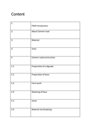
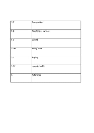
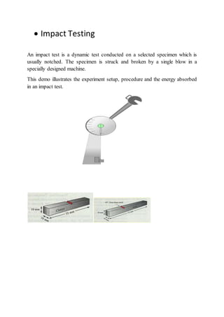
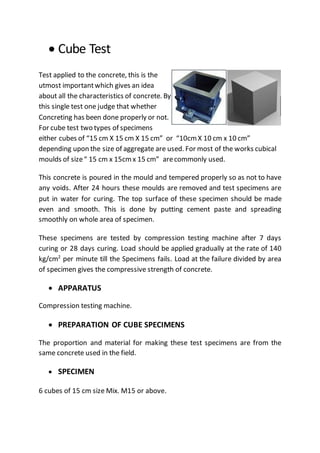
A
Summer Training Report
On
Cement ConcreteRoad
In
PWD
(PUBLIC WORKSDEPARTMENT)
Training Duration: 15/05/2017 to 14/07/2017
Report Submitted to:- Report Submitted by:-
Mr. Yogesh Agarwal Vijaypal Bagariya
Civil Engineering
B.Tech. - Final Year
Jaipur Engineering College and ResearchCentre
Acknowledgement
In the beginning of the report I want to give my thanks to Kamlesh Kumar
Choudhary (Head of Department of Civil Engineering Department) for all the
encouragement and appreciations that I have received from him.
I give my thanks To Asst.Prof. Yogesh Kumar Agarwal (P.T.I.V.
CORDINATOR) of the college for his kind valuable co-operation to arrange my
practical training in such a good place.
I also give my thanks to Mr. Tarachand Saini (Assistant Engineer)
CONSTRUCTION DIVISION NO-1,PWD,RINGUS(RAJ.) and Mr.
Rakesh Sharma (Junior Engineer) of for their kind co-operation and valuable
guidance.
Also I thank all the members of CONSTRUCTIONDIVISIONNO-1, PWD,Ringus
(RAJ.) Department for their kind support. They have always been a sourceof
inspiration to me.
Content
1.
PWD Introduction
2. About Cement road
3. Material
4. Tests
5. Cement road construction
5.1 Preparation of subgrade
5.2 Preparation of base
5.3 Formwork
5.4 Watering of base
5.5 Joints
5.6 Material mix & placing
5.7 Compaction
5.8 Finishing of surface
5.9 Curing
5.10 Filling joint
5.11 Edging
5.12 open to traffic
6. Reference
Introduction
Point of view geographic and population of the state is the nation's largest
state. State Industrial, economic and social development of the state and the
population of each village is absolutely necessary to re-connect to the main
roads. In addition to state important national roads, state roads and district
roads and their proper broad be made to improve the quality of traffic point of
view is of particular importance.
Public Works Department to build roads and improve connectivity in rural
zones, Other District Road and State broad and improvement of rural roads
and main routes narrow construction of zones and depleted bridges brides
reconstruction of the bases are transacted on a priority basis .
Under Pradhan Mantri Gram Sadak Yojana and pre-fabricated construction of
rural roads linking the work of other district roads broad Suddikrn the scale
bases are edited.
Successful operation of various schemes for the Public Works Department
engineers and supervisory boards in different districts of the engineer’s office
has been settled. Activities by planning, execution, and quality control etc.
remove impediments find joy in relation to the supervision over the activities
are focused. Various schemes operated by the Department of the Office of the
Regional Chief Engineers and Chief Engineers office.
About Road
A road is a thoroughfare, route, or way on land between two places, which has
been paved or otherwise improved to allow travel by some conveyance,
including a horse, cart, or motor vehicle. Roads consist of one, or sometimes
two, roadways (carriageways) each with one or more lanes and also any
associated sidewalks (British English: pavement) and road verges. Roads that
are available for use by the public may be referred to as public roads
or highways.
MATERIAL
Concrete is widely used in domestic, commercial, recreational, rural and
educational construction.
Communities around the world rely on concrete as a safe, strong and simple
building material. It is used in all types of construction; from domestic work to
multi-storey office blocks and shopping complexes.
Despite the common usage of concrete, few people are aware of the
considerations involved in designing strong, durable, high quality concrete.
There are mainly three types-
1-Cement
2-Sand
3-Aggregate
1. Cement
A cement is a binder, a substance that sets and hardens independently, and
can bind other materials together. The word "cement" traces to the Romans,
who used the term “caementicium” to describe masonry resembling
modern concrete that was made from crushed rock with burnt lime as binder.
The volcanic ash and pulverized brick additives that were added to the burnt
lime to obtain a hydraulic binder were later referred to as “cementum”,
“cimentum”, cement, and cement.
Cements used in construction can be characterized as being
either hydraulic or non-hydraulic. Hydraulic cements (e.g., Portland cement)
harden because of hydration, a chemical reaction between
the anhydrous cement powder and water. Thus, they can harden underwater
or when constantly exposed to wet weather. The chemical reaction results in
hydrates that are not very water-soluble and so are quite durable in water.
Non-hydraulic cements do not harden underwater; for example, slaked limes
harden by reaction with atmospheric carbon dioxide.
The most important uses of cement are as an ingredient in the production
of mortar in masonry, and of concrete, a combination of cement and an
aggregate to form a strong building material.
Types of Cement:-
1 Portlandcement
Portland cement is by far the most common type of cement in general use
around the world. This cement is made by heating limestone (calcium
carbonate) with small quantities of other materials (such as clay) to 1450 °C in
a kiln, in a process known as calcination, whereby a molecule of carbon
dioxide is liberated from the calcium carbonate to form calcium oxide, or
quicklime, which is then blended with the other materials that have been
included in the mix. The resulting hard substance, called 'clinker', is then
ground with a small amount of gypsum into a powder to make 'Ordinary
Portland Cement,the most commonly used type of cement (often referred to
as OPC).
Concrete is a composite material consisting of aggregate (gravel and sand),
cement, and water. As a construction material, concrete can be cast in almost
any shape desired, and once hardened, can become a structural (load bearing)
element. Portland cement may be grey or white.
1 Portland fly ash cement
Its contains up to 35% fly ash. The fly ash is pozzolanic, so that ultimate
strength is maintained. Because fly ash addition allows a lower concrete water
content, early strength can also be maintained. Where good quality cheap fly
ash is available, this can be an economic alternative to ordinary Portland
cement.
2 Portlandpozzolanacement
Its includes fly ash cement, since fly ash is a pozzolana , but also includes
cements made from other natural or artificial pozzolans. In countries
where volcanic ashes are available.
3 Portlandsilicafume cement
Addition of silica fume can yield exceptionally high strengths, and cements
containing 5–20% silica fume are occasionally produced. However, silica fume
is more usually added to Portland cement at the concrete mixer.
2. Sand
Sand is a naturally occurring granular material composed of finely divided
rock and mineral particles. The composition of sand is highly variable,
depending on the local rock sources and conditions, but the most common
constituent of sand in inland continental settings and non-tropical coastal
settings is silica (silicon dioxide, or SiO2), usually in the form of quartz.
The second most common type of sand is calcium carbonate, for
example aragonite, which has mostly been created, over the past half billion
years, by various forms of life, like coral and shellfish. It is, for example, the
primary form of sand apparent in areas where reefs have dominated the
ecosystem for millions of years like the Caribbean.
 Composition of Sand
In terms of particle size as used by geologists, sand particles range in diameter
from0.0625 mm(or 1⁄16 mm) to 2 mm. An individual particle in this range size
is termed a sand grain. Sand grains are between gravel (with particles ranging
from 2 mm up to 64 mm) and silt (particles smaller than 0.0625 mm down to
0.004 mm).
The size specification between sand and gravel has remained constant for
more than a century, but particle diameters as small as 0.02 mm were
considered sand under the Alter berg standard in use during the early 20th
century. A 1953 engineering standard published by the American Association
of State Highway and Transportation Officials set the minimum sand size at
0.074 mm. The composition of mineral sand is highly variable, depending on
the local rock sources and conditions. The bright white sand found in tropical
and subtropical coastal settings are eroded limestone and may
contain coral and shell fragments in addition to other organic or organically
derived fragmental material, suggesting sand formation depends on living
organisms, too. The gypsum sand dunes of the White Sands National
Monument in New Mexico are famous for their bright, white color. Arkose is a
sand or sandstone with considerable feldspar content, derived
from weathering and erosion of a (usually nearby) granitic rock outcrop. Some
sands contain magnetite, chlorite, glauconite or gypsum. Sands rich
in magnetite are dark to black in color, as are sands derived from
volcanic basalts and obsidian. Chlorite-glauconite bearing sands are typically
green in color, as are sands derived from basaltic (lava) with a
high olivine content. Many sands, especially those found extensively
in Southern Europe, have iron impurities within the quartz crystals of the sand,
giving a deep yellow color. Sand deposits in some areas contain garnets and
other resistant minerals, including some small gemstones.
3. Aggregate
Aggregates are inert granular materials such as sand, gravel, or crushed stone
that, along with water and Portland cement, are an essential ingredient in
concrete. For a good concrete mix, aggregates need to be clean, hard, strong
particles free of absorbed chemicals or coatings of clay and other fine
materials that could cause the deterioration of concrete. Aggregates, which
account for 60 to 75 percent of the total volume of concrete, are divided into
two distinct categories-fine and coarse. Fine aggregates generally consist of
natural sand or crushed stone with most particles passing through a 3/8-inch
(9.5-mm) sieve. Coarse aggregates are any particles greater than 0.19 inch
(4.75 mm), but generally range between 3/8 and 1.5 inches (9.5 mm to 37.5
mm) in diameter. Gravels constitute the majority of coarse aggregate used in
concrete with crushed stone making up most of the remainder.
Natural gravel and sand are usually dug or dredged from a pit, river, lake, or
seabed. Crushed aggregate is produced by crushing quarry rock, boulders,
cobbles, or large-size gravel. Recycled concrete is a viable source of aggregate
and has been satisfactorily used in granular subbases, soil-cement, and in new
concrete. Aggregate processing consists of crushing, screening, and washing
the aggregate to obtain proper cleanliness and gradation. If necessary, a
benefaction process such as jigging or heavy media separation can be used to
upgrade the quality.
Once processed, the aggregates are handled and stored in a way that
minimizes segregation and degradation and prevents contamination.
Aggregates strongly influence concrete's freshly mixed and hardened
properties, mixture proportions, and economy. Consequently, selection of
aggregates is an important process. Although some variation in aggregate
properties is expected.
Characteristics that are consideredwhenselecting aggregate include:
 grading
 durability
 particle shapeand surfacetexture
 abrasion and skid resistance
 unit weights and voids
 absorption and surfacemoisture
Grading refers to the determination of the particle-size distribution for
aggregate. Grading limits and maximum aggregate size are specified because
grading and size affect the amount of aggregate used as well as cement and
water requirements, workability.
 Shape and size
Particle shape and surface texture influence the properties of freshly mixed
concrete more than the properties of hardened concrete. Rough-textured,
angular, and elongated particles require more water to produce workable
concrete than smooth, rounded compact aggregate. Consequently, the cement
content must also be increased to maintain the water-cement ratio. Generally,
flat and elongated particles are avoided or are limited to about 15 percent by
weight of the total aggregate. Unit-weight measures the volume that graded
aggregate and the voids between them will occupy in concrete. The void
content between particles affects the amount of cement paste required for the
mix. Angular aggregate increase the void content. Larger sizes of well-graded
aggregate and improved grading decrease the void content. Absorption and
surfacemoistureof aggregate are measured when selecting aggregate because
the internal structure of aggregate is made up of solid material and voids that
may or may not contain water. The amount of water in the concrete mixture
must be adjusted to include the moisture conditions of the aggregate.
Abrasion and skid resistance of an aggregate are essential when the aggregate
is to be used in concrete constantly subject to abrasion as in heavy-duty floors
or pavements. Different minerals in the aggregate wear and polish at different
rates. Harder aggregate can be selected in highly abrasive conditions to
minimize wear.
Tests
1-The Slump Test.
2-Compression Test
3-ImpactTest
4-CubeTest
 THE SLUMP TEST
The slump test is done to make sure a concrete mix is workable.
Workability measures how easy the concrete is to place and handle .
TOOLS REQUIRED:
 Standard slump cone (100 mm top diameter x 200 mm bottom diameter
x 300 mm high).
 Small scoop Bullet-nosed rod (600mm long x 16 mm diameter).
 Slump plate (500 mm x 500 mm) .
Method
1 Dampen with water and place on the slump plate.Clean the cone.
The slump plate should be clean, firm, level and non-absorbent.
2 Collect a sample.
3
..
.
Stand firston the footpieces and fill1/3 the volume of the cone with
the sample.Compact the concrete by 'rodding'25 times.
Rodding: Rodding means to push a steel rod in and out of the
concrete to compact it into the cylinder, or slump cone.
Always rod in a definite pattern, working from outsideinto the middle.
4 Now fill 2/3 and again rod 25 times, justinto the top
of the first layer.
5 Fill overflowing, rodding again this time justinto the top
Top up the cone till it overflows.of the second layer.
6 Level off the surfacewith the steel rod using a rolling
Clean any concrete from aroundaction.
the baseand top of the cone, push down on the
handles and step off the footpieces.
7 Carefully lift the cone straightup making sure
not to move the sample.
8 Turnthe cone upsidedown and place the rod across the
up-turned cone.
 THE COMPRESSION TEST
The compression test shows the compressive strength of hardened concrete.
The testing is done in a laboratory off-site. The only work done on-site is to
make a concrete cylinder for the compression test.
The strength is measured in Megapascals (MPa) and is commonly specified as
a characteristic strength of concrete measured at 28 days after mixing. The
compressive strength is a measure of the concrete’s ability to resist loads
which tend to crush it.
Tools
 Cylinders (100 mmdiameter x 200 mm high or 150 mm diameter x 300
mm high)
( The small cylinders are normally used for most testing due to their
lighter weight )
 Small scoop
Bullet-nosed rod (600 mm x 16
mm)
 Steel float
 Steel plate
Method
1 Clean the cylinder mould and coat the inside lightly with form
oil, then place on a clean, level and firm surface, ie the steel
plate.
2 Collect a sample.
3 Fill 1/2 the volume of the mould with concrete then
compact by rodding 25 times. Cylinders may also be
compacted by vibrating using a vibrating table.
4 Fill the cone to overflowing and rod 25 times into
the top of the firstlayer, then top up the mould till
overflowing.
5 Level off the top with the steel float and clean any
concrete from around the mould.
6 Cap, clearly tag the cylinder
and put it in a cool dry place
to set for at least 24 hours.
7 After the mould is removed the cylinder is sent to the laboratory
whereit is cured and crushed to test compressivestrength.
 Impact Testing
An impact test is a dynamic test conducted on a selected specimen which is
usually notched. The specimen is struck and broken by a single blow in a
specially designed machine.
This demo illustrates the experiment setup, procedure and the energy absorbed
in an impact test.
 Cube Test
Test applied to the concrete, this is the
utmost importantwhich gives an idea
about all the characteristics of concrete. By
this single test one judge that whether
Concreting has been done properly or not.
For cube test two types of specimens
either cubes of “15 cm X 15 cm X 15 cm” or “10cmX 10 cm x 10 cm”
depending upon the size of aggregate are used. For most of the works cubical
moulds of size“ 15 cm x 15cmx 15 cm” arecommonly used.
This concrete is poured in the mould and tempered properly so as not to have
any voids. After 24 hours these moulds are removed and test specimens are
put in water for curing. The top surface of these specimen should be made
even and smooth. This is done by putting cement paste and spreading
smoothly on whole area of specimen.
These specimens are tested by compression testing machine after 7 days
curing or 28 days curing. Load should be applied gradually at the rate of 140
kg/cm2
per minute till the Specimens fails. Load at the failure divided by area
of specimen gives the compressive strength of concrete.
 APPARATUS
Compression testing machine.
 PREPARATION OF CUBE SPECIMENS
The proportion and material for making these test specimens are from the
same concrete used in the field.
 SPECIMEN
6 cubes of 15 cm size Mix. M15 or above.
 MIXING
Mix the concrete either by hand or in a laboratory batch mixer.
HAND MIXING
(i)Mix the cement and fine aggregate on a water tight none-absorbent
platform until the mixture is thoroughly blended and is of uniform color
(ii)Add the coarse aggregate and mix with cement and fine aggregate until the
coarse aggregate is uniformly distributed throughout the batch
(iii)Add water and mix it until the concrete appears to be homogeneous and of
the desired consistency.
 PRECAUTIONS
The water for curing should be tested every 7days and the temperature of
water must be at 27+2oC.
 PROCEDURE
(I) Remove the specimen from water after specified curing time and wipe out
excess water from the surface.
(II) Take the dimension of the specimen to the nearest 0.2m
(III) Clean the bearing surface of the testing machine
(IV) Place the specimen in the machine in such a manner that the load shall be
applied to the opposite sides of the cube cast.
(V) Align the specimen centrally on the base plate of the machine.
(VI) Rotate the movable portion gently by hand so that it touches the top
surface of the specimen.
(VII) Apply the load gradually without shock and continuously at the rate of
140kg/cm2
/minute till the specimen fails
(VIII) Record the maximum load and note any unusual features in the type of
failure.
Using mix Concrete , there some Point
to construct the road:
1. Preparation of base
2. Formworking
3. Preparation of subgrade
4. Watering of base
5. Joints
6. Material mix & placing
7. Compaction
8. Finishing of surface
(8A). Floating
(8B). Belting
(8C). Brooming
9. Curing
10. Joint filling
11. Edging
12. Open to traffic
1. Preparationof subgrade
1. Rolling on sub grade by roller
2. Filling the granular soil in the weak part and pot holes
3. Correctthe soil coat , Camber , longitudinal slop
When concrete direct laid on subgrade, For preventing the water-seepaging
into the soil , used water proof paper on entire length.
1. Rolling on sub gradeby roller
2. Filling the granular soil in the weak part and pot holes
3. Correctthe soil coat , Camber , longitudinal slop
When concrete direct laid on subgrade, For preventing the water-seepaging
into the soil , used water proof paper on entire length.
2. Preparationof base
Choose any one type of base
1. W.B.M. base
As base material of W.B.M. Road; stone ballast, concrete 10-15cm layer are
used. For bonding between concrete slab & W.B.M. used 1:2 cement wash on
W.B.M.
2. Concrete base
On the road used 10cm Cement concrete(1:2:4) or lime concrete(16:32:64)
3. Granular medium material layer
10-15cmcompositelayer of sand , moorum , bajri areused for better
drainage facilities
4. Stabilization soil
3. Form work
Material for form work-
Wooden sheets, battens, plywood, fibre hard board, steel plates, angles, rope,
minerals.
Formwork (shuttering) in concreteconstruction is used as a mould for a
structurein which fresh concreteis poured only to harden subsequently. Types
of concrete formwork construction depends on formwork materialand type of
structuralelement.
Formworks can also benamed based on the type of structuralmember
construction such as slab formwork for usein slab, beam formwork, column
formwork for usein beams and columns respectively etc.
The construction of formwork takes time and involves expenditure upto 20 to
25% of the costof the structureor even more. Design of these temporary
structures aremade to economic expenditure. The operation of removing the
formwork is known as stripping. Stripped formwork can bereused. Reusable
forms areknown as panel forms and non-usableare called stationary forms.
Timber is the mostcommon material used for formwork. Thedisadvantage
with timber formwork is that it will warp, swelland shrink. Application of water
impermeable costto the surfaceof wood mitigates these defects.
A good formwork should satisfy the following requirements:
1. Itshould be strong enough to withstand all types of dead and live
loads.
2. Itshould be rigidly constructed and efficiently propped and braced
both horizontally and vertically, so as to retain its shape.
3. The joints in the formwork should betight against leakage of cement
grout.
4. Construction of formwork should permitremovalof various parts in
desired sequences withoutdamage to the concrete.
5. The material of the formwork should becheap, easily available and
should be suitable for reuse.
6. The formwork should beset accurately to the desired line and levels
should have plane surface.
7. Itshould be as light as possible.
8. The material of the formwork should notwarp or get distorted when
exposed to the elements.
9. Itshould rest on firmbase.
5.Watering of base
If baseis dry then using the sprinkling process on it properly after that placing
the concrete.
5. Joints
Where is necessary to provide transverse, Longitudinal joints; there wedge
of woods, metals fix on level of concrete.
After setting of concrete it should be pull out.
If provided the dowel bar in joints, bars should be fit at right position.
Types of Joints:-
Joints are broadly divided into two types:
1. Longitudinal Joints:The joints which are provided parallel to the centre line
of the pavement, are called longitudinal joints.
2. Transverse Joints: Thejoints which are provided at right angles to the centre
line of the pavement are called transversejoints.
Requirementsof a Good Joint
The requirements of a good joint are listed below:
(i) A joint should not allow infiltration of water.
(ii) A joint should not permit ingress of stone grits.
(iii) A joint should move freely.
(iv) A joint should not protrude out the general level of the slab.
Transverse Joints
Transverse joints are further classified as:
(i) Expansion joint
(ii) Contraction joint
(iii) Warping joint
(iv) Construction joint
(i) Expansion Joints
These joints are provided to allow for the expansion of the slab due to rise in
the slab temperature. Expansion joints also permit contraction of the slab and
help to reduce warping stresses. Thegap width for this type of joints is
between 20 mm to 25 mm. Dowelbars are used to transfer the load to the
adjoining slab. Oneend of dowel bar is embedded effectively in one slab and
other end is kept free to allow for expansion. These bars are20 to 30 mm in
diameter and 400 to 700 mm is length. These bars are provided at an interval
of 300 mm. The spacing of these joints is given in table 1. A typical expansion
joint is shown in Fig.
.
(ii) Contraction Joints
These joints are provided to receive tension developed in concrete due to
contraction. Contraction joints are spaced closer than the expansion joints.
Depending upon the type of aggregates employed in the construction, the
recommended spacing of contraction joints are given in table 2.The transfer of
load at the joints is provided by the physicalinter-locking of the aggregates
projecting out at the joint faces. Fully bounded dowel bar is also used by some
agencies in the contraction joints for added safety.
(iii) Warping Joints
These are also called higher joints and are provided to relieve stresses included
due to warping. These joints are simply breaks in continuity of concrete which
allows a small amount of angular movement to occur between adjacent slabs.
These joints are rarely needed if the properly designed expansion and
contraction joints provided to prevent cracking. Warping joints are of two
types.
(iv) Construction Joints
These joints are provided when placing of concrete is suspended for more than
30 minutes. These are provided as transversejoints at the end of each day’s
work. Except for emergency stops, construction joints should belocated at the
regular place of expansion or contraction joints. If the construction joint is
located at the place of regular expansion joint, regular expansion joint is only
constructed. If it is located at the place of contraction joint, construction joints
should be used with dowel bars, shown in Fig.
Longitudinal Joints:-
On Subgradeof clay soil, longitudinal joints in cement concrete pavements are
provided to take careof differential shrinkageand swelling due to rapid
change of moisturecontent at the edges of the slab than at the centre. These
joints are provided to preventlongitudinal cracking in the concrete pavements
and are provided to pavements which havewidth over 4.5 m. The longitudinal
joints are either plain butt jointor butt joint with the bar Fig. shows the
different types of longitudinal joints.
Tongued and grooved joints are also used as longitudinal joints.
The tie bars in longitudinal joints are provided to hold the adjacent slabs
together
.
The length and spacing of tie bars adopted are 1.05 m and 0.60 m centre to
centre respectively. Table 3 gives the recommended size of tie bars based on
the traffic intensity.
6.Material mix & placing
Mixer is equipment that mix the concrete using distinct amount of
cement , concrete, sand and water. Concrete slab should have more
than 5-10cm thick cause of drying.
Used two type mixer-
1. Batch mixer-
At site, used for small road construction
2. Continuous mixer-
Continuous mixer used for large constuction .
If distance is more from site , mix concrete transported at site within
setting time.
Two methods generally used in placing of concrete-
1. Alternate bay method-
Placed the concrete on both side of road alternatively like as1,3,5…
part at one side and 2,4,6… part other side .
1st side
2nd side
This method have slow process due to road traffic problems.
2. Continuous bay method-
construct one side of road regularly, if completed some part of
first side than construct other side. This method have fast process
without no obstruction of traffic
7. Compaction
Purpose of compaction is that to pull out air from void and make
concrete harden.
Compaction done by-
1. mechanically surface vibrator
2. manually hand tempers
8. Finishing of surface
1.Floating-
For levelling the surface use floating, scree-ding , power trowel. So
that there is no acceptable more than 3mm variation in concrete level
surface.
2.Belting-
For making surface clean used belting process. Belt is nothing but a
15-30cm thick sheets of canvass which have more length than road.
3. Brooming-
Brooming is the process in which we made rough surface parallel to
road by brush. It is useful in avoiding slip & comfortable travelling on
road . The depth of line on road no more than 1.5mm.
9.Curing
Curing is the name of increasing the hydration process of cement.
after setting the concrete , curing process done till 14-28days.
Some methods of curing are-
1.Shading concrete works
2. Covering with hessian & gunny bags
3.Sprinkling of water
4.Steamcuring
5. Membrane curing
6. By Ponding
10. Filling joint
After drying road, clean the joints and fill the shelling compound or hot
bitumen .
11. Edging
To protect damaging the sides of concrete pavements used over
burntbrick work. In placeof bricks, providekerb of pre mix concrete.
12.open to traffic
Generally after a month, road should be open to traffic.
If used rapid hardening cement it take 7 days to open traffic.
Reference
Websites;
 www.Google.com
 www.concrete.net.au
 www.res.gov.in
 www.upjl.com
 www.concrete.com
Books;
 Concrete Technology By M.S.Sheety.
 Concrete Technology By Neville & Brooks.
 Highway Engineering By Khanna & CG Justo.
 Highway Engineering By Rangawala.

Summer training report on cement Road Construction

  • 1.
    A Summer Training Report On CementConcreteRoad In PWD (PUBLIC WORKSDEPARTMENT) Training Duration: 15/05/2017 to 14/07/2017 Report Submitted to:- Report Submitted by:- Mr. Yogesh Agarwal Vijaypal Bagariya Civil Engineering B.Tech. - Final Year Jaipur Engineering College and ResearchCentre
  • 2.
    Acknowledgement In the beginningof the report I want to give my thanks to Kamlesh Kumar Choudhary (Head of Department of Civil Engineering Department) for all the encouragement and appreciations that I have received from him. I give my thanks To Asst.Prof. Yogesh Kumar Agarwal (P.T.I.V. CORDINATOR) of the college for his kind valuable co-operation to arrange my practical training in such a good place. I also give my thanks to Mr. Tarachand Saini (Assistant Engineer) CONSTRUCTION DIVISION NO-1,PWD,RINGUS(RAJ.) and Mr. Rakesh Sharma (Junior Engineer) of for their kind co-operation and valuable guidance. Also I thank all the members of CONSTRUCTIONDIVISIONNO-1, PWD,Ringus (RAJ.) Department for their kind support. They have always been a sourceof inspiration to me.
  • 3.
    Content 1. PWD Introduction 2. AboutCement road 3. Material 4. Tests 5. Cement road construction 5.1 Preparation of subgrade 5.2 Preparation of base 5.3 Formwork 5.4 Watering of base 5.5 Joints 5.6 Material mix & placing
  • 4.
    5.7 Compaction 5.8 Finishingof surface 5.9 Curing 5.10 Filling joint 5.11 Edging 5.12 open to traffic 6. Reference
  • 5.
    Introduction Point of viewgeographic and population of the state is the nation's largest state. State Industrial, economic and social development of the state and the population of each village is absolutely necessary to re-connect to the main roads. In addition to state important national roads, state roads and district roads and their proper broad be made to improve the quality of traffic point of view is of particular importance. Public Works Department to build roads and improve connectivity in rural zones, Other District Road and State broad and improvement of rural roads and main routes narrow construction of zones and depleted bridges brides reconstruction of the bases are transacted on a priority basis . Under Pradhan Mantri Gram Sadak Yojana and pre-fabricated construction of rural roads linking the work of other district roads broad Suddikrn the scale bases are edited. Successful operation of various schemes for the Public Works Department engineers and supervisory boards in different districts of the engineer’s office has been settled. Activities by planning, execution, and quality control etc. remove impediments find joy in relation to the supervision over the activities are focused. Various schemes operated by the Department of the Office of the Regional Chief Engineers and Chief Engineers office.
  • 6.
    About Road A roadis a thoroughfare, route, or way on land between two places, which has been paved or otherwise improved to allow travel by some conveyance, including a horse, cart, or motor vehicle. Roads consist of one, or sometimes two, roadways (carriageways) each with one or more lanes and also any associated sidewalks (British English: pavement) and road verges. Roads that are available for use by the public may be referred to as public roads or highways. MATERIAL Concrete is widely used in domestic, commercial, recreational, rural and educational construction. Communities around the world rely on concrete as a safe, strong and simple building material. It is used in all types of construction; from domestic work to multi-storey office blocks and shopping complexes. Despite the common usage of concrete, few people are aware of the considerations involved in designing strong, durable, high quality concrete. There are mainly three types- 1-Cement 2-Sand 3-Aggregate
  • 7.
    1. Cement A cementis a binder, a substance that sets and hardens independently, and can bind other materials together. The word "cement" traces to the Romans, who used the term “caementicium” to describe masonry resembling modern concrete that was made from crushed rock with burnt lime as binder. The volcanic ash and pulverized brick additives that were added to the burnt lime to obtain a hydraulic binder were later referred to as “cementum”, “cimentum”, cement, and cement. Cements used in construction can be characterized as being either hydraulic or non-hydraulic. Hydraulic cements (e.g., Portland cement) harden because of hydration, a chemical reaction between the anhydrous cement powder and water. Thus, they can harden underwater or when constantly exposed to wet weather. The chemical reaction results in hydrates that are not very water-soluble and so are quite durable in water. Non-hydraulic cements do not harden underwater; for example, slaked limes harden by reaction with atmospheric carbon dioxide. The most important uses of cement are as an ingredient in the production of mortar in masonry, and of concrete, a combination of cement and an aggregate to form a strong building material. Types of Cement:- 1 Portlandcement Portland cement is by far the most common type of cement in general use around the world. This cement is made by heating limestone (calcium carbonate) with small quantities of other materials (such as clay) to 1450 °C in a kiln, in a process known as calcination, whereby a molecule of carbon dioxide is liberated from the calcium carbonate to form calcium oxide, or quicklime, which is then blended with the other materials that have been included in the mix. The resulting hard substance, called 'clinker', is then ground with a small amount of gypsum into a powder to make 'Ordinary
  • 8.
    Portland Cement,the mostcommonly used type of cement (often referred to as OPC). Concrete is a composite material consisting of aggregate (gravel and sand), cement, and water. As a construction material, concrete can be cast in almost any shape desired, and once hardened, can become a structural (load bearing) element. Portland cement may be grey or white. 1 Portland fly ash cement Its contains up to 35% fly ash. The fly ash is pozzolanic, so that ultimate strength is maintained. Because fly ash addition allows a lower concrete water content, early strength can also be maintained. Where good quality cheap fly ash is available, this can be an economic alternative to ordinary Portland cement. 2 Portlandpozzolanacement Its includes fly ash cement, since fly ash is a pozzolana , but also includes cements made from other natural or artificial pozzolans. In countries where volcanic ashes are available. 3 Portlandsilicafume cement Addition of silica fume can yield exceptionally high strengths, and cements containing 5–20% silica fume are occasionally produced. However, silica fume is more usually added to Portland cement at the concrete mixer.
  • 9.
    2. Sand Sand isa naturally occurring granular material composed of finely divided rock and mineral particles. The composition of sand is highly variable, depending on the local rock sources and conditions, but the most common constituent of sand in inland continental settings and non-tropical coastal settings is silica (silicon dioxide, or SiO2), usually in the form of quartz. The second most common type of sand is calcium carbonate, for example aragonite, which has mostly been created, over the past half billion years, by various forms of life, like coral and shellfish. It is, for example, the primary form of sand apparent in areas where reefs have dominated the ecosystem for millions of years like the Caribbean.  Composition of Sand In terms of particle size as used by geologists, sand particles range in diameter from0.0625 mm(or 1⁄16 mm) to 2 mm. An individual particle in this range size is termed a sand grain. Sand grains are between gravel (with particles ranging from 2 mm up to 64 mm) and silt (particles smaller than 0.0625 mm down to 0.004 mm). The size specification between sand and gravel has remained constant for more than a century, but particle diameters as small as 0.02 mm were considered sand under the Alter berg standard in use during the early 20th century. A 1953 engineering standard published by the American Association of State Highway and Transportation Officials set the minimum sand size at 0.074 mm. The composition of mineral sand is highly variable, depending on
  • 10.
    the local rocksources and conditions. The bright white sand found in tropical and subtropical coastal settings are eroded limestone and may contain coral and shell fragments in addition to other organic or organically derived fragmental material, suggesting sand formation depends on living organisms, too. The gypsum sand dunes of the White Sands National Monument in New Mexico are famous for their bright, white color. Arkose is a sand or sandstone with considerable feldspar content, derived from weathering and erosion of a (usually nearby) granitic rock outcrop. Some sands contain magnetite, chlorite, glauconite or gypsum. Sands rich in magnetite are dark to black in color, as are sands derived from volcanic basalts and obsidian. Chlorite-glauconite bearing sands are typically green in color, as are sands derived from basaltic (lava) with a high olivine content. Many sands, especially those found extensively in Southern Europe, have iron impurities within the quartz crystals of the sand, giving a deep yellow color. Sand deposits in some areas contain garnets and other resistant minerals, including some small gemstones. 3. Aggregate Aggregates are inert granular materials such as sand, gravel, or crushed stone that, along with water and Portland cement, are an essential ingredient in concrete. For a good concrete mix, aggregates need to be clean, hard, strong particles free of absorbed chemicals or coatings of clay and other fine materials that could cause the deterioration of concrete. Aggregates, which account for 60 to 75 percent of the total volume of concrete, are divided into two distinct categories-fine and coarse. Fine aggregates generally consist of natural sand or crushed stone with most particles passing through a 3/8-inch (9.5-mm) sieve. Coarse aggregates are any particles greater than 0.19 inch (4.75 mm), but generally range between 3/8 and 1.5 inches (9.5 mm to 37.5 mm) in diameter. Gravels constitute the majority of coarse aggregate used in concrete with crushed stone making up most of the remainder.
  • 11.
    Natural gravel andsand are usually dug or dredged from a pit, river, lake, or seabed. Crushed aggregate is produced by crushing quarry rock, boulders, cobbles, or large-size gravel. Recycled concrete is a viable source of aggregate and has been satisfactorily used in granular subbases, soil-cement, and in new concrete. Aggregate processing consists of crushing, screening, and washing the aggregate to obtain proper cleanliness and gradation. If necessary, a benefaction process such as jigging or heavy media separation can be used to upgrade the quality. Once processed, the aggregates are handled and stored in a way that minimizes segregation and degradation and prevents contamination. Aggregates strongly influence concrete's freshly mixed and hardened properties, mixture proportions, and economy. Consequently, selection of aggregates is an important process. Although some variation in aggregate properties is expected. Characteristics that are consideredwhenselecting aggregate include:  grading  durability  particle shapeand surfacetexture  abrasion and skid resistance  unit weights and voids  absorption and surfacemoisture Grading refers to the determination of the particle-size distribution for aggregate. Grading limits and maximum aggregate size are specified because grading and size affect the amount of aggregate used as well as cement and water requirements, workability.
  • 12.
     Shape andsize Particle shape and surface texture influence the properties of freshly mixed concrete more than the properties of hardened concrete. Rough-textured, angular, and elongated particles require more water to produce workable concrete than smooth, rounded compact aggregate. Consequently, the cement content must also be increased to maintain the water-cement ratio. Generally, flat and elongated particles are avoided or are limited to about 15 percent by weight of the total aggregate. Unit-weight measures the volume that graded aggregate and the voids between them will occupy in concrete. The void content between particles affects the amount of cement paste required for the mix. Angular aggregate increase the void content. Larger sizes of well-graded aggregate and improved grading decrease the void content. Absorption and surfacemoistureof aggregate are measured when selecting aggregate because the internal structure of aggregate is made up of solid material and voids that may or may not contain water. The amount of water in the concrete mixture must be adjusted to include the moisture conditions of the aggregate. Abrasion and skid resistance of an aggregate are essential when the aggregate is to be used in concrete constantly subject to abrasion as in heavy-duty floors or pavements. Different minerals in the aggregate wear and polish at different rates. Harder aggregate can be selected in highly abrasive conditions to minimize wear. Tests 1-The Slump Test. 2-Compression Test 3-ImpactTest 4-CubeTest
  • 13.
     THE SLUMPTEST The slump test is done to make sure a concrete mix is workable. Workability measures how easy the concrete is to place and handle . TOOLS REQUIRED:  Standard slump cone (100 mm top diameter x 200 mm bottom diameter x 300 mm high).  Small scoop Bullet-nosed rod (600mm long x 16 mm diameter).  Slump plate (500 mm x 500 mm) .
  • 14.
    Method 1 Dampen withwater and place on the slump plate.Clean the cone. The slump plate should be clean, firm, level and non-absorbent. 2 Collect a sample. 3 .. . Stand firston the footpieces and fill1/3 the volume of the cone with the sample.Compact the concrete by 'rodding'25 times. Rodding: Rodding means to push a steel rod in and out of the concrete to compact it into the cylinder, or slump cone. Always rod in a definite pattern, working from outsideinto the middle. 4 Now fill 2/3 and again rod 25 times, justinto the top of the first layer. 5 Fill overflowing, rodding again this time justinto the top Top up the cone till it overflows.of the second layer. 6 Level off the surfacewith the steel rod using a rolling Clean any concrete from aroundaction. the baseand top of the cone, push down on the handles and step off the footpieces. 7 Carefully lift the cone straightup making sure not to move the sample. 8 Turnthe cone upsidedown and place the rod across the up-turned cone.
  • 15.
     THE COMPRESSIONTEST The compression test shows the compressive strength of hardened concrete. The testing is done in a laboratory off-site. The only work done on-site is to make a concrete cylinder for the compression test. The strength is measured in Megapascals (MPa) and is commonly specified as a characteristic strength of concrete measured at 28 days after mixing. The compressive strength is a measure of the concrete’s ability to resist loads which tend to crush it. Tools  Cylinders (100 mmdiameter x 200 mm high or 150 mm diameter x 300 mm high) ( The small cylinders are normally used for most testing due to their lighter weight )  Small scoop Bullet-nosed rod (600 mm x 16 mm)  Steel float  Steel plate Method 1 Clean the cylinder mould and coat the inside lightly with form oil, then place on a clean, level and firm surface, ie the steel plate. 2 Collect a sample.
  • 16.
    3 Fill 1/2the volume of the mould with concrete then compact by rodding 25 times. Cylinders may also be compacted by vibrating using a vibrating table. 4 Fill the cone to overflowing and rod 25 times into the top of the firstlayer, then top up the mould till overflowing. 5 Level off the top with the steel float and clean any concrete from around the mould. 6 Cap, clearly tag the cylinder and put it in a cool dry place to set for at least 24 hours. 7 After the mould is removed the cylinder is sent to the laboratory whereit is cured and crushed to test compressivestrength.
  • 17.
     Impact Testing Animpact test is a dynamic test conducted on a selected specimen which is usually notched. The specimen is struck and broken by a single blow in a specially designed machine. This demo illustrates the experiment setup, procedure and the energy absorbed in an impact test.
  • 18.
     Cube Test Testapplied to the concrete, this is the utmost importantwhich gives an idea about all the characteristics of concrete. By this single test one judge that whether Concreting has been done properly or not. For cube test two types of specimens either cubes of “15 cm X 15 cm X 15 cm” or “10cmX 10 cm x 10 cm” depending upon the size of aggregate are used. For most of the works cubical moulds of size“ 15 cm x 15cmx 15 cm” arecommonly used. This concrete is poured in the mould and tempered properly so as not to have any voids. After 24 hours these moulds are removed and test specimens are put in water for curing. The top surface of these specimen should be made even and smooth. This is done by putting cement paste and spreading smoothly on whole area of specimen. These specimens are tested by compression testing machine after 7 days curing or 28 days curing. Load should be applied gradually at the rate of 140 kg/cm2 per minute till the Specimens fails. Load at the failure divided by area of specimen gives the compressive strength of concrete.  APPARATUS Compression testing machine.  PREPARATION OF CUBE SPECIMENS The proportion and material for making these test specimens are from the same concrete used in the field.  SPECIMEN 6 cubes of 15 cm size Mix. M15 or above.
  • 19.
     MIXING Mix theconcrete either by hand or in a laboratory batch mixer. HAND MIXING (i)Mix the cement and fine aggregate on a water tight none-absorbent platform until the mixture is thoroughly blended and is of uniform color (ii)Add the coarse aggregate and mix with cement and fine aggregate until the coarse aggregate is uniformly distributed throughout the batch (iii)Add water and mix it until the concrete appears to be homogeneous and of the desired consistency.  PRECAUTIONS The water for curing should be tested every 7days and the temperature of water must be at 27+2oC.  PROCEDURE (I) Remove the specimen from water after specified curing time and wipe out excess water from the surface. (II) Take the dimension of the specimen to the nearest 0.2m (III) Clean the bearing surface of the testing machine (IV) Place the specimen in the machine in such a manner that the load shall be applied to the opposite sides of the cube cast. (V) Align the specimen centrally on the base plate of the machine. (VI) Rotate the movable portion gently by hand so that it touches the top surface of the specimen. (VII) Apply the load gradually without shock and continuously at the rate of 140kg/cm2 /minute till the specimen fails (VIII) Record the maximum load and note any unusual features in the type of failure.
  • 20.
    Using mix Concrete, there some Point to construct the road: 1. Preparation of base 2. Formworking 3. Preparation of subgrade 4. Watering of base 5. Joints 6. Material mix & placing 7. Compaction 8. Finishing of surface (8A). Floating (8B). Belting (8C). Brooming 9. Curing 10. Joint filling 11. Edging 12. Open to traffic
  • 21.
    1. Preparationof subgrade 1.Rolling on sub grade by roller 2. Filling the granular soil in the weak part and pot holes 3. Correctthe soil coat , Camber , longitudinal slop When concrete direct laid on subgrade, For preventing the water-seepaging into the soil , used water proof paper on entire length. 1. Rolling on sub gradeby roller 2. Filling the granular soil in the weak part and pot holes 3. Correctthe soil coat , Camber , longitudinal slop When concrete direct laid on subgrade, For preventing the water-seepaging into the soil , used water proof paper on entire length. 2. Preparationof base Choose any one type of base 1. W.B.M. base As base material of W.B.M. Road; stone ballast, concrete 10-15cm layer are used. For bonding between concrete slab & W.B.M. used 1:2 cement wash on W.B.M. 2. Concrete base On the road used 10cm Cement concrete(1:2:4) or lime concrete(16:32:64) 3. Granular medium material layer
  • 22.
    10-15cmcompositelayer of sand, moorum , bajri areused for better drainage facilities 4. Stabilization soil 3. Form work Material for form work- Wooden sheets, battens, plywood, fibre hard board, steel plates, angles, rope, minerals. Formwork (shuttering) in concreteconstruction is used as a mould for a structurein which fresh concreteis poured only to harden subsequently. Types of concrete formwork construction depends on formwork materialand type of structuralelement.
  • 23.
    Formworks can alsobenamed based on the type of structuralmember construction such as slab formwork for usein slab, beam formwork, column formwork for usein beams and columns respectively etc. The construction of formwork takes time and involves expenditure upto 20 to 25% of the costof the structureor even more. Design of these temporary structures aremade to economic expenditure. The operation of removing the formwork is known as stripping. Stripped formwork can bereused. Reusable forms areknown as panel forms and non-usableare called stationary forms. Timber is the mostcommon material used for formwork. Thedisadvantage with timber formwork is that it will warp, swelland shrink. Application of water impermeable costto the surfaceof wood mitigates these defects. A good formwork should satisfy the following requirements: 1. Itshould be strong enough to withstand all types of dead and live loads. 2. Itshould be rigidly constructed and efficiently propped and braced both horizontally and vertically, so as to retain its shape. 3. The joints in the formwork should betight against leakage of cement grout. 4. Construction of formwork should permitremovalof various parts in desired sequences withoutdamage to the concrete. 5. The material of the formwork should becheap, easily available and should be suitable for reuse. 6. The formwork should beset accurately to the desired line and levels should have plane surface. 7. Itshould be as light as possible. 8. The material of the formwork should notwarp or get distorted when exposed to the elements. 9. Itshould rest on firmbase.
  • 24.
    5.Watering of base Ifbaseis dry then using the sprinkling process on it properly after that placing the concrete.
  • 25.
    5. Joints Where isnecessary to provide transverse, Longitudinal joints; there wedge of woods, metals fix on level of concrete. After setting of concrete it should be pull out. If provided the dowel bar in joints, bars should be fit at right position. Types of Joints:- Joints are broadly divided into two types: 1. Longitudinal Joints:The joints which are provided parallel to the centre line of the pavement, are called longitudinal joints. 2. Transverse Joints: Thejoints which are provided at right angles to the centre line of the pavement are called transversejoints.
  • 26.
    Requirementsof a GoodJoint The requirements of a good joint are listed below: (i) A joint should not allow infiltration of water. (ii) A joint should not permit ingress of stone grits. (iii) A joint should move freely. (iv) A joint should not protrude out the general level of the slab. Transverse Joints Transverse joints are further classified as: (i) Expansion joint (ii) Contraction joint (iii) Warping joint (iv) Construction joint (i) Expansion Joints These joints are provided to allow for the expansion of the slab due to rise in the slab temperature. Expansion joints also permit contraction of the slab and help to reduce warping stresses. Thegap width for this type of joints is between 20 mm to 25 mm. Dowelbars are used to transfer the load to the adjoining slab. Oneend of dowel bar is embedded effectively in one slab and other end is kept free to allow for expansion. These bars are20 to 30 mm in
  • 27.
    diameter and 400to 700 mm is length. These bars are provided at an interval of 300 mm. The spacing of these joints is given in table 1. A typical expansion joint is shown in Fig. .
  • 28.
    (ii) Contraction Joints Thesejoints are provided to receive tension developed in concrete due to contraction. Contraction joints are spaced closer than the expansion joints. Depending upon the type of aggregates employed in the construction, the recommended spacing of contraction joints are given in table 2.The transfer of load at the joints is provided by the physicalinter-locking of the aggregates projecting out at the joint faces. Fully bounded dowel bar is also used by some agencies in the contraction joints for added safety. (iii) Warping Joints These are also called higher joints and are provided to relieve stresses included due to warping. These joints are simply breaks in continuity of concrete which allows a small amount of angular movement to occur between adjacent slabs. These joints are rarely needed if the properly designed expansion and contraction joints provided to prevent cracking. Warping joints are of two types.
  • 29.
    (iv) Construction Joints Thesejoints are provided when placing of concrete is suspended for more than 30 minutes. These are provided as transversejoints at the end of each day’s work. Except for emergency stops, construction joints should belocated at the regular place of expansion or contraction joints. If the construction joint is located at the place of regular expansion joint, regular expansion joint is only constructed. If it is located at the place of contraction joint, construction joints should be used with dowel bars, shown in Fig.
  • 30.
    Longitudinal Joints:- On Subgradeofclay soil, longitudinal joints in cement concrete pavements are provided to take careof differential shrinkageand swelling due to rapid change of moisturecontent at the edges of the slab than at the centre. These joints are provided to preventlongitudinal cracking in the concrete pavements and are provided to pavements which havewidth over 4.5 m. The longitudinal joints are either plain butt jointor butt joint with the bar Fig. shows the different types of longitudinal joints. Tongued and grooved joints are also used as longitudinal joints. The tie bars in longitudinal joints are provided to hold the adjacent slabs together . The length and spacing of tie bars adopted are 1.05 m and 0.60 m centre to centre respectively. Table 3 gives the recommended size of tie bars based on the traffic intensity.
  • 31.
    6.Material mix &placing Mixer is equipment that mix the concrete using distinct amount of cement , concrete, sand and water. Concrete slab should have more than 5-10cm thick cause of drying. Used two type mixer- 1. Batch mixer- At site, used for small road construction 2. Continuous mixer- Continuous mixer used for large constuction . If distance is more from site , mix concrete transported at site within setting time. Two methods generally used in placing of concrete- 1. Alternate bay method- Placed the concrete on both side of road alternatively like as1,3,5… part at one side and 2,4,6… part other side . 1st side 2nd side This method have slow process due to road traffic problems. 2. Continuous bay method- construct one side of road regularly, if completed some part of first side than construct other side. This method have fast process without no obstruction of traffic
  • 32.
    7. Compaction Purpose ofcompaction is that to pull out air from void and make concrete harden. Compaction done by- 1. mechanically surface vibrator 2. manually hand tempers 8. Finishing of surface 1.Floating- For levelling the surface use floating, scree-ding , power trowel. So that there is no acceptable more than 3mm variation in concrete level surface. 2.Belting- For making surface clean used belting process. Belt is nothing but a 15-30cm thick sheets of canvass which have more length than road. 3. Brooming- Brooming is the process in which we made rough surface parallel to road by brush. It is useful in avoiding slip & comfortable travelling on road . The depth of line on road no more than 1.5mm.
  • 33.
    9.Curing Curing is thename of increasing the hydration process of cement. after setting the concrete , curing process done till 14-28days. Some methods of curing are- 1.Shading concrete works 2. Covering with hessian & gunny bags 3.Sprinkling of water
  • 34.
  • 35.
    10. Filling joint Afterdrying road, clean the joints and fill the shelling compound or hot bitumen . 11. Edging To protect damaging the sides of concrete pavements used over burntbrick work. In placeof bricks, providekerb of pre mix concrete. 12.open to traffic Generally after a month, road should be open to traffic. If used rapid hardening cement it take 7 days to open traffic.
  • 36.
    Reference Websites;  www.Google.com  www.concrete.net.au www.res.gov.in  www.upjl.com  www.concrete.com Books;  Concrete Technology By M.S.Sheety.  Concrete Technology By Neville & Brooks.  Highway Engineering By Khanna & CG Justo.  Highway Engineering By Rangawala.