Download to read offline
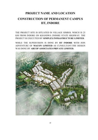


This document provides a project report on the construction of the permanent campus of the Indian Institute of Technology Indore. It was submitted by Dilip Patidar in partial fulfillment of his Bachelor of Technology degree in Civil Engineering. The report details various aspects of the construction process including shuttering, reinforcement, concrete work, finishing work and quality control tests. It provides architectural drawings and photos of the different buildings constructed on campus such as the podium building, hostels, residences and more.


