Downloaded 173 times
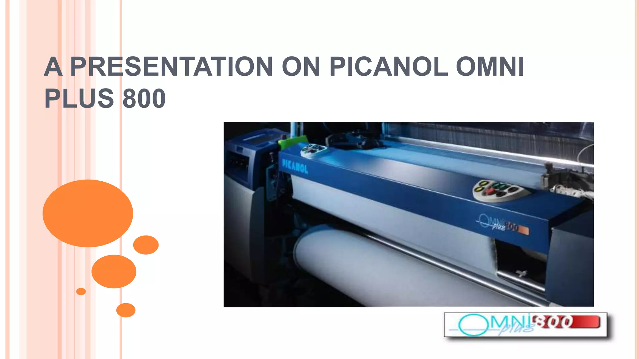
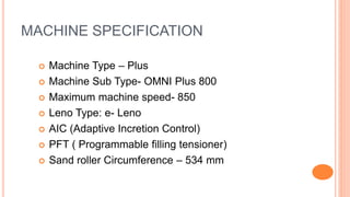
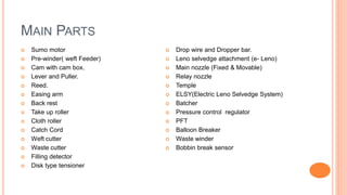


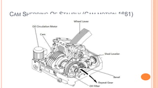
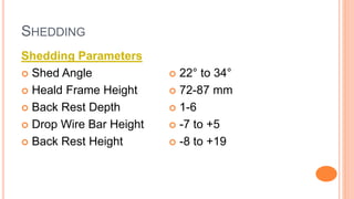
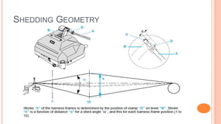


The document provides information on the Picanol Omni Plus 800 air jet weaving machine. It describes the machine specifications including a maximum speed of 850 rpm. It outlines the main parts of the machine such as the sumo motor, pre-winder, reed, and temples. It discusses the key motions including shedding, picking, and beat up. It provides details on the shedding mechanism and parameters. It also describes the pre-winder, nozzles, and air pressure used for weft insertion. The document summarizes the let-off, take up, and stop motions powered by servo motors. It concludes by listing the various motors used in the air jet loom.


![Yarn Manufacturing Process : Comber Part II [Modern combers]](https://cdn.slidesharecdn.com/ss_thumbnails/moderncombers-180912060904-thumbnail.jpg?width=640&height=640&fit=bounds)


