The document details advancements in LAS 1.4 lidar processing and the features of Merrick & Company's MARS® software, including support for new point data record formats, classification enhancements, and compliance with USGS lidar base specifications. Key highlights include improvements in data normalization, support for additional color bands, and enhanced data handling capabilities. The presentation also covers the automation of quality control for lidar data as per updated specifications.


![Copyright © 2015 Merrick & Company - All rights reserved.
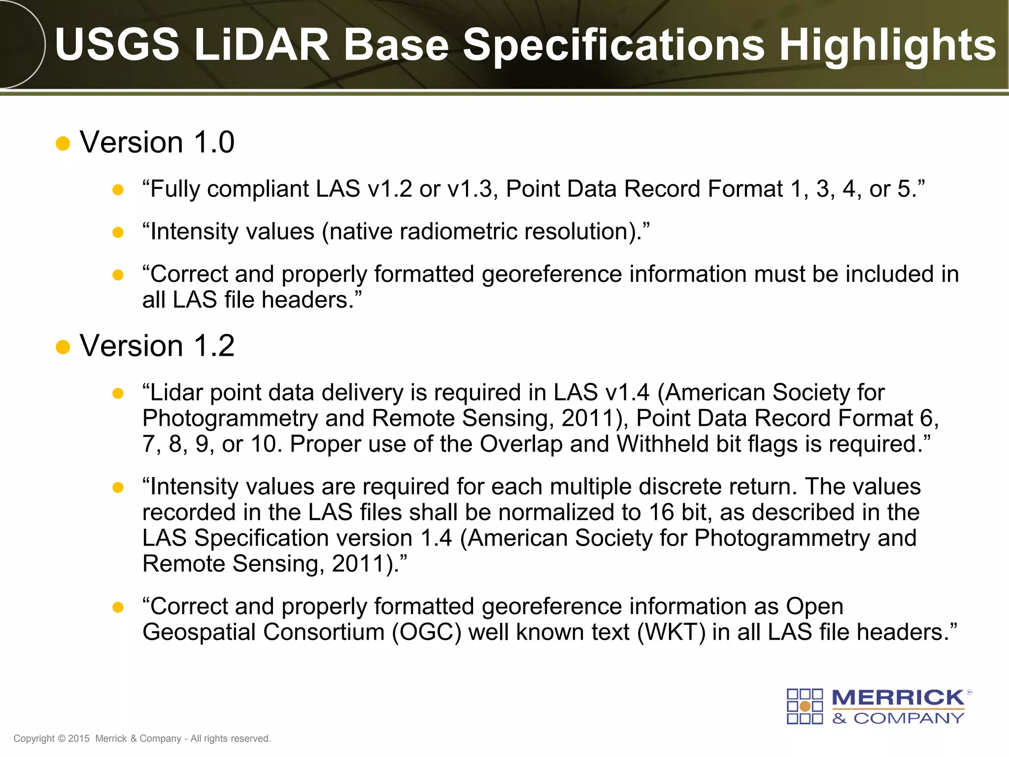
What’s New in LAS 1.4?
Point Data Record Formats (PDRF) 6-10 [MARS® 6-8]
Option for Extended Variable Length Record (EVLR) for
general use
Dedicated use of Well Known Text (WKT) for CRS
Point attribute additions of overlap bit flag and sensor
channel bit
Support for up to 15 returns
New scan angle format increasing stored resolution
Intensity and RGBN normalization
Fourth colorization band support (RGBN)
Support for up to 256 classes with new definitions](https://image.slidesharecdn.com/2015ilscbethel-190806214433/75/A-LiDAR-Processing-Workflow-Supporting-LAS-1-4-and-Testing-for-USGS-NGP-Base-Specification-Compliance-6-2048.jpg)


![IPv6 Transition Strategies Tutorial, by Philip Smith [APNIC 38]](https://cdn.slidesharecdn.com/ss_thumbnails/apnic38-ipv6-transition-strategies1410239823-140916190234-phpapp02-thumbnail.jpg?width=640&height=640&fit=bounds)