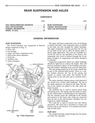
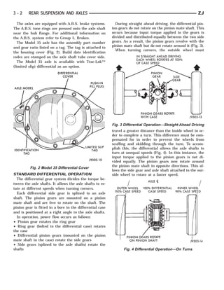
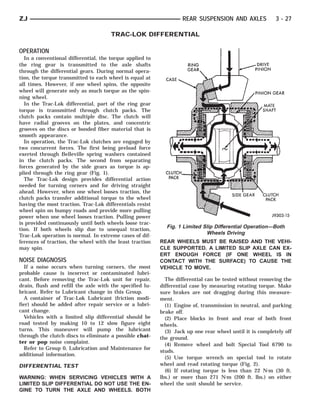
The document provides information about rear suspension and axles for a Grand Cherokee vehicle. It describes the main components of the rear suspension system, including coil springs, upper and lower suspension arms, shock absorbers, stabilizer bar, track bar, and jounce bumpers. It also explains how the standard differential allows the axle shafts to rotate at different speeds when turning corners to compensate for the longer path of the outside wheel. The Model 35 axle used in the Grand Cherokee can be equipped with an optional Trac-Lok limited slip differential.
The document provides information on servicing the front suspension and axle of a Grand Cherokee vehicle. It discusses components like the track bar, stabilizer bar, upper and lower suspension arms, coil springs, shock absorbers and bushings. The summary also covers procedures for front wheel alignment, diagnosis of noise/vibration issues, specifications and torque values.
This document provides information on propeller shafts. It discusses:
1) There are three types of propeller shafts used on 4WD vehicles, differing by their joint configurations and whether they include a slip yoke.
2) Universal joints are used to allow the propeller shaft to operate at different angles and are not repairable if damaged.
3) Vibration can be caused by an unbalanced propeller shaft, worn or misaligned universal joints, or other vehicle component issues like loose engine mounts. Diagnosis procedures include measuring runout and clamping sections to isolate the source.
The document provides information on standard service procedures for engines, including form-in-place gaskets, honing cylinder bores, measuring crankshaft and connecting rod bearing clearances using Plastigage, repairing damaged or worn threads using a Heli-Coil tap, and servicing a 4.0L engine assembly (short block). It includes diagrams and step-by-step instructions for compression testing, measuring bearing clearance, and honing cylinder bores. Tables of contents and indexes provide page references for additional information on specific engines and procedures.
The document discusses the frame and bumpers of the Jeep Grand Cherokee. It notes that the Grand Cherokee does not have a conventional frame, but rather a unitized body and frame construction made of high-strength steel. It describes how to diagnose collision damage and properly repair a unibody structure. The document provides removal and installation instructions for the front and rear bumpers, as well as the front and rear tow hooks. Measurement points for the frame are also indicated to ensure proper alignment during repair.
This document contains information about brakes for a vehicle model. It includes sections on general brake information, ABS brakes, changes for the 1995 model year, brake components, fluids and cleaning products, safety precautions, and an index of topics. The key points are:
- The vehicle uses power assisted four-wheel disc brakes with ABS standard on all models.
- Changes for 1995 include different master cylinder, power brake booster, and hydraulic control unit components for the ABS system.
- Safety precautions for working on brakes include wearing protective equipment and properly disposing of any potential asbestos dust.
This document provides information about propeller shafts and driveline angles. It includes:
- Descriptions of propeller shaft components and their purpose in transmitting power from the transmission to the axle.
- Guidelines for proper propeller shaft lubrication, phasing, and maximum operating angles based on engine speed.
- Procedures for diagnosing and testing for vibration, imbalance, and runout.
- Steps for measuring driveline angles using an inclinometer to evaluate the transmission output angle, propeller shaft angle, and axle input angle.
This document provides information about wheels, tires, and their maintenance. It discusses tire identification, inflation pressures, wear patterns, and replacement. The document also covers wheel installation, balance, and replacement. Proper maintenance of wheels and tires, such as regular inflation and rotation, can improve vehicle performance and safety.
Introduction to brakes and its classificationNavroz Navodia
This presentation contains a brief introduction to brake and its principle.Along with that it contains a detailed classification of all the brakes which are as follows
1 mechanical brakes
2 hydraulic brakes
3 disc brakes
4 pneumatic brakes
As this presentation mainly focuses on mechanical brakes hence subtype of following brake are also discussed.they are
1 SINGLE SHOE AND DOUBLE SHOE BRAKE
2 DIFFERENTIAL BRAKE
3 INTERNAL EXPANDING BRAKES
4 PIVOTED SHOE BRAKE
5 BAND BRAKES
The document provides information about manual transmissions and transfer cases used in Jeep vehicles, including:
- An index listing transmission and transfer case models covered
- Service information for the AX15 5-speed manual transmission, including identification, gear ratios, lubrication, diagnosis and repair procedures
- Procedures for transmission removal, disassembly, component inspection and installation
The document discusses various types of CASNUB bogies used in Indian railways. It provides details of the components and features of CASNUB -22W, -22W(M), -22W(Retrofitted), -22NL, -22NLB, -22NLM, and -22HS bogies. The bogies comprise side frames, a bolster, springs, a centre pivot arrangement, friction plates, and other components. The document also outlines inspection and maintenance criteria for key bogie components like the adapter and side frames.
Independent suspension allows each wheel on the same axle to move vertically independently of the other. It is common for modern vehicles to have independent front suspension (IFS) and some to have independent rear suspension (IRS) as well. Independent suspension offers better ride quality and handling due to lower unsprung weight and each wheel's ability to react individually to the road. Some common independent suspension system types are MacPherson strut, double wishbone, and multi-link systems.
Misalignment impact on prouduction and how to solve these issues. Learn the effects of misalignment in your Aggregate conveyor line. Help is on the way. the doctor is in the house !
The 1UZ-FE engine is a 4.0-liter V8 with 32 valves and DOHC design. It produces 250 horsepower at 5,600 rpm and 260 ft-lbs of torque at 4,400 rpm. Key features include a compact design achieved through a scissors gear mechanism and lightweight materials, low noise and vibration, and high reliability ensured by features like plastic tightening bolts. The engine is controlled by an ECU to maintain peak performance and efficiency.
Hyster c004 (s120 e) forklift service repair manualfjsjefksekkksemm
This document provides instructions for servicing and repairing steering axles on various lift truck models. It describes the components of the steering axle assembly and different types of pivot mounts used. Procedures are provided for removing and installing steering axles with stub shaft mounts and rubber mounts. The document also provides instructions for removing and servicing wheel hubs, spindles, bearings and tie rods. Safety warnings are given for putting lift trucks on blocks or stands when performing maintenance.
1) Skew is the position of the roller axis with respect to the rotating drum axis. If they are parallel there is zero skew, if not parallel the roller is skewed and creates axial thrust on the drum.
2) Skewed rollers can accelerate wear by creating uneven load distribution, loss of contact and high stress points, and slipping/skidding between the roller and drum.
3) Understanding the bearing style is key to determining the axial position and direction of skew for each roller. Fixed plain sleeve bearings with thrust buttons can be checked by striking the end caps to identify which end has thrust.
The document discusses the requirements and components of a clutch mechanism. It provides details on:
1. The key requirements of a clutch include transmitting maximum engine torque without slippage, dissipating large amounts of heat generated, engaging gradually without jerks, being dynamically balanced, damping vibrations, having minimum inertia when disengaged, and requiring minimal force to disengage.
2. The main components of a clutch are the clutch plate, friction facings, pressure plate, springs, throwout bearing, and release levers. The clutch plate transfers torque via friction facings attached to its steel plate. The pressure plate applies pressure to the clutch plate via springs.
3. Different types of clutches include single
This document provides details on the design features of a FIAT bogie used in Indian railways. It describes the main sub-systems of the bogie including the Y-frame bogie, wheelset, primary and secondary suspensions, braking system, and principles of force transmission. It also provides specifications of materials used, dimensions of wheelsets, suspension variants for different coach types, and performance parameters like speed limit and ride index.
The document discusses various types of bogies and suspension systems used in Indian railways. It provides details of the CASNUB bogie, including its general description and features. The CASNUB bogie assembly consists of various components like side frames, bolster, spring plank, wheels, axles, axle boxes, and center pivot arrangement. Construction and maintenance details are provided for each of these components. Wear limits and tolerances for replacement are also specified.
The document provides details on the design features of a bogie, including its frame, materials used, imported bogie items, suspensions, wheels, brakes, and problems reported. It describes the bogie's primary and secondary suspensions, which use springs, dampers, and other components to connect the wheel set to the bogie frame and vehicle body. The document also lists specifications, dimensions, and condemning limits for various bogie parts.
The document discusses various exterior body components of a vehicle. It provides removal and installation instructions for components like the grille, headlamps, hood, hood latches and related parts. The document is organized in sections covering the grille/reinforcement, radiator support, hood, hood hinges/latches/striker and other exterior parts. Diagrams and step-by-step instructions are provided for servicing these exterior body parts.
The document describes the design features of a FIAT bogie used in trains. It includes descriptions of the bogie frame, wheelset, primary and secondary suspensions, brake systems, and other components. The bogie is designed to support coaches at speeds up to 160kph, using components like nested coil springs, dampers, and an anti-roll bar to provide stability and ride comfort during operation. Material specifications and dimensions are provided for key parts.
A bicycle brake reduces the speed of a bicycle or prevents it from moving. The three main types are: rim brakes, disc brakes, and drum brakes. There have been various types of brake used throughout history, and several are still in use today
This document provides an overview of bogie assembly for locomotives. It describes that a bogie is a three-axle frame that supports the weight of the locomotive and runs on six wheels. The key components of a bogie include the bogie frame, axles, wheels, traction motors, suspension system, and brake rigging. It then discusses the types of bogies based on wheel arrangement and frame construction, as well as the important parts, suspension arrangement, and ride characteristics.
This document provides information about steering systems for ZJ vehicles. It describes the major components of the power steering system including the recirculating ball steering gear, steering linkage, power steering pump, and steering column. It provides details on identifying codes for the steering gear and pump as well as diagnosing common noise complaints.
This document provides information about heating and air conditioning systems. It discusses the components and operation of both manual and automatic temperature control systems. It covers the heater core, evaporator, condenser, compressor, refrigerant lines, and sensors. It provides warnings and cautions for safely servicing the A/C system. Refrigerant R-134a is used, which requires special equipment, hoses, and oil compared to R-12.
This document provides general information about audio systems for Jeep Grand Cherokee models. It describes components such as radios, speakers, antennas, and amplifiers. It also provides diagnostic procedures and service instructions for removing and installing these components.
The document provides information on turn signal and hazard warning systems. It describes the main components, which include a combination flasher, multi-function switch, turn signal indicator lamps, and turn signal lamps. It outlines procedures for diagnosing issues and testing components like the flasher and switch. Removal and installation instructions are provided for the multi-function switch and combination flasher.
This document provides information about power seats in Jeep Grand Cherokee models. It describes the major components of the power seat system, including the power seat switch and three reversible motors that operate the seat adjustments. The document provides guidance on diagnosing issues with the power seat motors or switch, including continuity tests of the switch connections. It also outlines procedures for removing and installing the power seat switch and motor/adjuster assembly.
The document provides general information about emission control systems, including:
1) It describes the different emission control components and systems used on 4.0L and 5.2L engines.
2) It explains how the on-board diagnostic system checks for faults in emission components like the EGR and EVAP systems.
3) It provides an overview of the evaporative emission control system and its components like the EVAP canister.
This document provides information about exhaust systems and intake manifolds. It discusses the basic components of exhaust systems, including exhaust manifolds, pipes, catalytic converters, heat shields, mufflers and tailpipes. It describes symptoms of exhaust system problems and provides procedures for removing and installing exhaust pipes and manifolds. Intake manifolds and catalytic converters are also discussed.
The document provides information about heat treatment processes. It defines heat treatment as a process of heating and cooling metals and alloys in the solid state to change their properties. Heat treatment is done to change properties like strength, hardness, toughness etc. of steels. The key heat treatment processes described are annealing, normalizing, hardening and tempering. Annealing involves heating steel above or below its critical temperature, holding, and slow cooling to soften it and relieve stresses. The goals, processes, and effects of various annealing types like full annealing and spheroidizing annealing are explained.
This document provides information about a vehicle theft alarm system, including:
- General descriptions of how the system arms, disarms, and responds to unauthorized access attempts.
- Instructions for performing self-diagnosis tests to check the operation of sensors and circuits.
- Procedures for technicians to remove and install the VTA module, which involves removing various dash panel components.
- Steps for technicians to diagnose the system using the self-diagnosis mode and by checking for proper horn responses from sensors.
The document provides information about the overhead console in Jeep Grand Cherokee models. It describes the different types of overhead consoles that are used depending on whether the vehicle has a power sunroof option. It also describes the major components in the overhead console including the trip computer, compass, thermometer, reading lamps, remote garage door opener storage, and sunglasses storage. The document provides details on diagnosing issues with these components through self-diagnostic tests and flow charts.
This document provides information about power mirrors and an automatic day/night rear view mirror on Jeep Grand Cherokee models. It describes the major components of these systems and their functions. The document also provides diagnostic procedures to test the power mirror switch and motors, as well as the automatic rear view mirror. Finally, it lists the service procedures for removing and installing the power mirror switch and removing the power mirrors and automatic rear view mirror.
This document provides an overview of fuel delivery systems for vehicles with 4.0L and 5.2L engines. It describes the components of the fuel pump module, which is mounted in the fuel tank and contains the electric fuel pump, fuel pressure regulator, and in-tank fuel filter. The fuel pressure regulator is no longer mounted on the fuel rail. Procedures are provided for releasing fuel system pressure before servicing, and for testing fuel system pressure.
The document discusses different types of axles used in vehicles. It describes front axles which support the front of the vehicle and facilitate steering. Front axles can be dead axles, which do not rotate, or live axles which transmit power to the front wheels. Rear axles support the weight of the vehicle and transmit driving thrust. The document outlines full-floating, semi-floating, and three-quarter floating rear axles and how they differ in how they carry weight and transmit torque. It also discusses stub axles which connect to the front axle and allow the front wheels to turn for steering.
The suspension system connects a vehicle to its wheels and serves two purposes - contributing to handling and braking while protecting the vehicle and cargo from damage. There are different types of suspension systems including conventional, independent, air, and hydraulic systems. An independent suspension system allows each wheel to move independently of the other wheels, improving ride quality. Common independent front systems are MacPherson strut and double wishbone suspensions.
The document provides information on rear axle drives and rear axle shafts. It discusses the Hotchkiss drive system which uses leaf springs to locate the rear axle and transmit driving forces. It is a simple and inexpensive design. The document also describes torque tube drives and compares them to Hotchkiss drives. Finally, it discusses different types of rear axle shafts including semi-floating, full-floating, and three-quarter floating axles.
The document contains a list of various vehicle service manuals, repair manuals, and technical manuals for automobiles, motorcycles, tractors, snowblowers, and other vehicles from manufacturers such as John Deere, Chevrolet, Ferrari, Nissan, Subaru, Suzuki, Yamaha, and others. The manuals cover a range of vehicle models from the 1940s through the 2000s and include shop manuals, repair manuals, technical manuals, and more.
The document provides information on vehicle suspension systems. It discusses the key components of a suspension system including springs, dampers, and linkages. The goals of a suspension system are to contribute to vehicle handling/braking performance while keeping occupants comfortable by isolating them from road bumps and noise. The suspension supports the vehicle's weight, provides a smooth ride, and protects the vehicle from damage. Common types of suspension systems include dependent systems that link the two wheels and independent systems where each wheel can move independently. Key aspects like sprung mass, unsprung mass, suspension types, and springs are also summarized.
The document provides information about suspension systems and steering systems in automobiles. It contains questions and answers related to suspension components like springs, shock absorbers, and axles. It also discusses steering geometry, types of steering gears, and steering mechanisms like Ackerman and Davis steering systems. The key points are:
1. The document discusses common suspension components like leaf springs, coil springs, shock absorbers, and how they work to provide a comfortable ride while maintaining vehicle control.
2. It addresses steering systems and their purpose to provide directional stability. Different types of steering gears and their functions are explained.
3. Steering mechanisms like Ackerman and Davis are summarized, with Davis steering using sliding
This document provides information about front suspension components and alignment specifications for a vehicle. It describes the front suspension system which uses upper and lower control arms, coil springs, shock absorbers, and a stabilizer bar. It provides instructions for inspecting, diagnosing, and adjusting components like wheel bearings, ball joints, and toe alignment. Specifications are given for caster, camber, toe alignment, and torque values for fasteners.
The document summarizes different types of suspension systems used in automobiles. It describes the objectives of a suspension system which are to prevent road shocks from being transmitted to vehicle components, safeguard occupants from shocks, and preserve stability. It then discusses various spring systems including leaf springs, coil springs, and rubber springs. It also mentions shock absorbers, independent suspension systems, and specific types like wishbone and MacPherson strut suspensions.
This document describes five main types of independent suspension systems: 1) MacPherson strut, 2) Wishbone, 3) Vertical guide, 4) Trailing link, and 5) Swinging half axles. It provides details on each system, including components, how they function, advantages and disadvantages. For example, it explains that the MacPherson strut system uses a lower wishbone and strut with shock absorber/coil spring to position the wheel. This system provides maximum engine compartment space and is commonly used in front-wheel drive cars.
The document discusses front axles and steering systems. It defines different types of front axles including dead, line, and stub axles. It also describes the four types of stub axles: Elliot, reversed Elliot, Lamoine, and reversed Lamoine. The steering system section covers steering geometry including camber, caster, king pin inclination, and toe. It also discusses Ackermann steering geometry and different steering gear boxes such as worm and sector, rack and pinion. In summary, the document provides an overview of front axle and steering system components and geometry.
The document discusses different components of a vehicle's suspension system. It begins by defining sprung mass and unsprung mass. Sprung mass refers to parts of the vehicle supported by the suspension, like the body and frame. Unsprung mass includes components below the suspension like wheels. The document then covers various types of springs used in suspension systems, including leaf springs, coil springs, rubber springs, and torsion bars. It also discusses shock absorbers and their purpose of controlling spring motion. Finally, the key functions of a suspension system are outlined as isolating the vehicle from road shocks and providing stability, comfort, and road handling ability.
The document provides an overview of vehicle suspension systems. It discusses the history and evolution of suspension systems from 1903 to the 1960s. It describes the main functions of a suspension system as isolating the vehicle from road shocks while maintaining stability. The key elements are springs, which absorb shocks, and dampers, which restrict bouncing. Common types of springs include leaf springs, coil springs, torsion bars, and air/gas springs. Dampers reduce oscillation through hydraulic resistance.
The document discusses various types of automobile suspension systems. It describes independent suspension systems that allow each wheel to move independently and non-independent systems where the wheels are attached to a solid axle. Common types of independent suspension include MacPherson strut suspension, wishbone suspension, and solid rear axle suspension. The document also covers suspension components like springs, shock absorbers, control arms, and sway bars. It provides advantages and disadvantages of different suspension types.
This document summarizes different types of automobile suspension systems. It describes rigid and independent suspension systems and the main types of each: coil springs, leaf springs, air springs, and torsion bars. It provides details on wishbone and MacPherson strut independent suspension designs. The key components of suspension systems are identified including control arms, ball joints, springs, and shock absorbers. The functions and advantages/disadvantages of different suspension components are outlined.
Bearings are used in machines to allow rotating parts to move freely while supporting loads. There are two main types of bearings: sliding contact/frictional bearings which operate on sliding friction; and rolling contact/anti-frictional bearings which have rolling elements like balls or rollers to reduce friction. Rolling contact bearings can carry heavier loads than sliding contact bearings and have lower friction, but are more complex and expensive to manufacture. Bearings are classified based on the type of load they support, such as radial loads, axial/thrust loads, or combined loads. Common bearing types include ball bearings, roller bearings, tapered roller bearings, and needle roller bearings.
This document discusses key terms and concepts related to steering system design, including camber, caster, directional stability, geometric centerline, toe, parallelism, and Ackerman steering. It provides definitions and explanations of these terms. For example, it explains that caster provides directional stability and the ability of wheels to return to the straight ahead position after a turn. It also discusses various steering system types like rack and pinion steering and their advantages and disadvantages.
The document discusses suspension systems and springs used in vehicle suspension systems. It describes the main types of suspension systems including dependent, independent, and semi-dependent. It then focuses on MacPherson strut suspension systems, why they are commonly used, and how they work. The document then discusses different types of springs used in suspensions including extension, compression, torsion, and leaf springs. It provides details on spring materials, manufacturing processes, and key spring terminology.
The document discusses different types of brakes used on bicycles and other vehicles. It begins by introducing Bike Brake Store, which specializes in high quality braking components. It then defines and provides details on regenerative brakes, bicycle brakes, including their history and common types like spoon brakes, duck brakes, and rim brakes. The document also covers brake pads, rod-actuated brakes, caliper brake designs, and side-pull and center-pull caliper brakes.
This document discusses different types of brakes, how they work, and their applications. It classifies brakes based on their configuration and mode of actuation. The main types described are shoe/block brakes, drum brakes, disc brakes, band brakes, and band and block brakes. These brakes use friction to slow or stop motion by pressing brake pads or shoes against a spinning drum or disc. Their applications include use in vehicles, trains, cranes, and material handling equipment.
Mahaveer Enterprises is an importer and trader of bearings and SKF plumber blocks established in 2006. It offers a variety of bearings from major brands for industries like machinery, textiles, and mining. The company prides itself on competitive prices, timely deliveries, and good client relations to maintain an edge over competitors in the market.
Mahaveer Enterprises is an importer and trader of various kinds of bearings and SKF plumber blocks that was established in 2006. It exports popular bearing brands like SKF, NSK, NTN, and others. The types of bearings it imports and trades include deep groove ball bearings, self-aligning ball bearings, cylindrical roller bearings, tapered roller bearings, and others. These bearings serve industries like machinery, textiles, railways, and metallurgy.
The document discusses various components that connect the transmission to the drive wheels, including the propeller shaft, universal joints, constant velocity joints, and slip joints. It provides details on the construction and function of each component. The propeller shaft transmits power from the transmission to the rear differential. Universal joints and constant velocity joints allow the shaft to transmit power through varying angles, while slip joints allow adjustments to the shaft length during vehicle movement.
This document appears to be an electronic service manual for the 1995 Jeep Grand Cherokee. The logo on the page links to instructions when clicked. The page requests the user click the link for further information.
This document provides information about cooling system diagnosis and service procedures for a vehicle. It includes:
- An overview of cooling system components and coolant routing
- Diagnosis charts to help identify potential causes of overheating
- Procedures for testing the water pump, draining and refilling the cooling system, and replacing components like the radiator, hoses, thermostat, and water pump.
- Cautions for working on the high-pressure cooling system and ensuring the correct rotating water pump is installed.
This document provides contact information for obtaining special service tools in the United States, Canada, and internationally. The same tools or their equivalent are required for certain vehicle service operations and can be obtained from local sources or through the listed contacts, which include addresses and phone/fax numbers for Miller Special Tools in Michigan and C&D Riley Enterprises in Ontario.
The document provides information about diagnosing issues with a vehicle's rear window defogger system. It describes the major components of the system, including the rear window glass grid, defogger switch, and defogger relay/timer. It then lists steps to test overall system operation and to isolate problems, such as using a voltmeter to check for breaks in the glass grid lines or testing power supply to the relay.
The document provides information on servicing a clutch system. It includes:
- Descriptions of clutch components and their functions.
- Procedures for diagnosing clutch problems through road testing, inspection of components for contamination, misalignment or excessive wear.
- Guidelines for checking flywheel and clutch disc runout and how to address issues found.
- Causes of clutch housing misalignment and how it can lead to premature wear.
- Charts outlining common clutch faults, their causes and recommended corrective actions.
- Steps for removal and installation of clutch cover/disc, housing, hydraulic linkage, pedal, pilot/release bearings and flywheel service.
The
This document provides instructions and cautions for automotive service professionals. It advises that all repair procedures should follow the manufacturer's recommendations. Special tools may be required for some procedures, and safety goggles should always be worn. Cautions are included to minimize risks of injury from components like clips and springs. The manufacturer cannot test all procedures, so service professionals must ensure personal and vehicle safety. Contact information is provided to order service manuals.
(1) The document provides general information about the horn system components in a Grand Cherokee, including the horn switch, horn relay, and horns.
(2) Diagnosis instructions check the fuse, horn relay connections, horn switch wiring, and horn ground before replacing components.
(3) Service procedures are provided for removing and installing the horn switch, horns, and horn relay. The horn switch is accessed through the steering wheel and airbag module. Horns are mounted under the right front fender. The horn relay is located in the relay center in the glove box.
This document is the 1995 Jeep Grand Cherokee service manual published by Chrysler Corporation. It provides service and repair instructions for technicians working on 1995 Jeep Grand Cherokee vehicles. The manual is divided into groups covering different vehicle systems. It notes that specific tools are required for some procedures and instructions on where to order them. The manual also reserves the right for Chrysler to make changes to vehicles or manuals without obligation.
The document provides instructions for viewing and navigating service manuals on CD-ROM using the Acrobat Reader. It describes how to access manuals in Windows 98/95/NT and Windows 3.1, and explains the welcome page, tab page, viewing contents within groups, and using bookmarks to navigate. It also summarizes the basic features of the Acrobat Reader toolbar for navigating manuals.
This document provides an index and contents for the Electrical Group 8A manual, focusing on diagnosing battery, starting, and charging systems. It begins with an overview that these systems are interconnected and should be tested as a complete unit. The document then covers batteries, describing battery components, ratings, diagnosing state-of-charge using built-in indicators or testing electrolyte levels. It also covers starting and charging systems. Testing procedures range from basic to using onboard diagnostics.
Este documento proporciona una lista de descripciones de grupos y páginas para varios componentes y sistemas de vehículos. La lista incluye descripciones breves de varios componentes del motor, la transmisión, la suspensión, el sistema de aire acondicionado y otros sistemas.
The document provides information on ignition system components, operation, and diagnostics for Chrysler vehicles. It includes descriptions of components like the ignition coil, distributor, oxygen sensor, and powertrain control module. The diagnostics section provides testing procedures for components such as the camshaft position sensor, crankshaft position sensor, and oxygen sensors. It also discusses using the DRB scan tool and onboard diagnostics to test the ignition system.
Welcome to ASP Cranes, your trusted partner for crane solutions in Raipur, Chhattisgarh! With years of experience and a commitment to excellence, we offer a comprehensive range of crane services tailored to meet your lifting and material handling needs.
At ASP Cranes, we understand the importance of reliable and efficient crane operations in various industries, from construction and manufacturing to logistics and infrastructure development. That's why we strive to deliver top-notch solutions that enhance productivity, safety, and cost-effectiveness for our clients.
Our services include:
Crane Rental: Whether you need a crawler crane for heavy lifting or a hydraulic crane for versatile operations, we have a diverse fleet of well-maintained cranes available for rent. Our rental options are flexible and can be customized to suit your project requirements.
Crane Sales: Looking to invest in a crane for your business? We offer a wide selection of new and used cranes from leading manufacturers, ensuring you find the perfect equipment to match your needs and budget.
Crane Maintenance and Repair: To ensure optimal performance and safety, regular maintenance and timely repairs are essential for cranes. Our team of skilled technicians provides comprehensive maintenance and repair services to keep your equipment running smoothly and minimize downtime.
Crane Operator Training: Proper training is crucial for safe and efficient crane operation. We offer specialized training programs conducted by certified instructors to equip operators with the skills and knowledge they need to handle cranes effectively.
Custom Solutions: We understand that every project is unique, which is why we offer custom crane solutions tailored to your specific requirements. Whether you need modifications, attachments, or specialized equipment, we can design and implement solutions that meet your needs.
At ASP Cranes, customer satisfaction is our top priority. We are dedicated to delivering reliable, cost-effective, and innovative crane solutions that exceed expectations. Contact us today to learn more about our services and how we can support your project in Raipur, Chhattisgarh, and beyond. Let ASP Cranes be your trusted partner for all your crane needs!
Learn why monitoring your Mercedes' Exhaust Back Pressure (EBP) sensor is crucial. Understand its role in engine performance and emission reduction. Discover five warning signs of EBP sensor failure, from loss of power to increased emissions. Take action promptly to avoid costly repairs and maintain your Mercedes' reliability and efficiency.
The Octavia range embodies the design trend of the Škoda brand: a fusion of
aesthetics, safety and practicality. Whether you see the car as a whole or step
closer and explore its unique features, the Octavia range radiates with the
harmony of functionality and emotion
What Are The Immediate Steps To Take When The VW Temperature Light Starts Fla...Import Motorworks
Learn how to respond when the red temperature light flashes in your VW with this presentation. From checking coolant levels to seeking professional help, follow these steps promptly to prevent engine damage and ensure safety on the road.
Your VW's camshaft position sensor is crucial for engine performance. Signs of failure include engine misfires, difficulty starting, stalling at low speeds, reduced fuel efficiency, and the check engine light. Prompt inspection and replacement can prevent further damage and keep your VW running smoothly.
How To Fix The Key Not Detected Issue In Mercedes CarsIntegrity Motorcar
Experiencing a "Key Not Detected" problem in your Mercedes? Don’t take it for granted. Go through this presentation to find out the exact nature of the issue you are dealing with. Have your vehicle checked by a certified professional if necessary.
Ever been troubled by the blinking sign and didn’t know what to do?
Here’s a handy guide to dashboard symbols so that you’ll never be confused again!
Save them for later and save the trouble!
What Could Cause The Headlights On Your Porsche 911 To Stop WorkingLancer Service
Discover why your Porsche 911 headlights might flicker out unexpectedly. From aging bulbs to electrical gremlins and moisture mishaps, we're delving into the reasons behind the blackout. Stay tuned to illuminate the road ahead and ensure your lights shine bright for safer journeys.
Fleet management these days is next to impossible without connected vehicle solutions. Why? Well, fleet trackers and accompanying connected vehicle management solutions tend to offer quite a few hard-to-ignore benefits to fleet managers and businesses alike. Let’s check them out!
Digital Fleet Management - Why Your Business Need It?
95ZJ_3.PDF
1. ZJ REAR SUSPENSION AND AXLES 3-1
REAR SUSPENSION AND AXLES
CONTENTS
page page
AXLE NOISE/VIBRATION DIAGNOSIS . . . . . . . . . 6 REAR SUSPENSION . . . . . . . . . . . . . . . . . . . . . . 3
AXLE SPECIFICATIONS . . . . . . . . . . . . . . . . . . . 32 TORQUE SPECIFICATIONS . . . . . . . . . . . . . . . . 32
GENERAL INFORMATION . . . . . . . . . . . . . . . . . . 1 TRAC-LOK DIFFERENTIAL . . . . . . . . . . . . . . . . . 27
MODEL 35 AXLE . . . . . . . . . . . . . . . . . . . . . . . . 10
GENERAL INFORMATION
REAR SUSPENSION The upper and lower suspension arms use bushings
The Grand Cherokee rear suspension is link/coil to isolate road noise. The suspension arms are bolted
design comprised of (Fig. 1); to the body and axle through the rubber bushings.
• Drive axle The upper suspension arm has provision for the use
• Coil springs of cam bolts at the axle to allow for pinion angle or
• Upper and lower suspension arms thrust angle adjustment. The cams are available as a
service kit and are not installed at the factory. The
• Dual-action shock absorbers
suspension arm travel is limited through the of use
• Track bar
jounce bumpers in compression and shock absorbers
• Stabilizer bar
in rebound.
• Jounce bumpers
Suspension components which use rubber bushings
should be tightened at vehicle ride height. This will
prevent premature failure of the bushing and main-
tain ride comfort. Bushings must never be lubricated.
The coil springs mount up in the fender shield that
is part of the unitized body bracket. There is a rub-
ber isolator between the top of the spring and
bracket to isolate road noise. The bottom of the
spring seats on the axle pad and is retained with a
clip.
The shock absorbers dampen jounce and rebound of
the vehicle over various road conditions. The top of
the shock absorbers are bolted to the body. The bot-
tom of the shocks are bolted to the axle shock ab-
sorber bracket.
The stabilizer bar is used to control vehicle body
roll during turns. The spring steel bar helps to equal-
ize the vehicle body in relationship to the suspension.
The bar extends across the underside of the chassis
and connects to the frame rails. Links are connected
from the bar to the axle brackets. Stabilizer bar are
isolated by rubber bushings.
The track bar is used to control rear axle lateral
movement. The track bar is attached to a frame rail
bracket and an axle bracket. It is isolated with bush-
ings at both ends.
REAR AXLE
The integral housing, hypoid design has the pinion
Fig. 1 Rear Suspension set below the ring gear.
2. 3-2 REAR SUSPENSION AND AXLES ZJ
The axles are equipped with A.B.S. brake systems. During straight ahead driving, the differential pin-
The A.B.S. tone rings are pressed onto the axle shaft ion gears do not rotate on the pinion mate shaft. This
near the hub flange. For additional information on occurs because input torque applied to the gears is
the A.B.S. system refer to Group 5, Brakes. divided and distributed equally between the two side
The Model 35 axle has the assembly part number gears. As a result, the pinion gears revolve with the
and gear ratio listed on a tag. The tag is attached to pinion mate shaft but do not rotate around it (Fig. 3).
When turning corners, the outside wheel must
the housing cover (Fig. 2). Build date identification
codes are stamped on the axle shaft tube cover side.
The Model 35 axle is available with Trac-Lok™
(limited slip) differential as an option.
Fig. 3 Differential Operation—Straight-Ahead Driving
travel a greater distance than the inside wheel in or-
der to complete a turn. This difference must be com-
pensated for in order to prevent the wheels from
scuffing and skidding through the turn. To accom-
plish this, the differential allows the axle shafts to
turn at unequal speeds (Fig. 4). In this instance, the
input torque applied to the pinion gears is not di-
vided equally. The pinion gears now rotate around
the pinion mate shaft in opposite directions. This al-
Fig. 2 Model 35 Differential Cover
lows the side gear and axle shaft attached to the out-
STANDARD DIFFERENTIAL OPERATION side wheel to rotate at a faster speed.
The differential gear system divides the torque be-
tween the axle shafts. It allows the axle shafts to ro-
tate at different speeds when turning corners.
Each differential side gear is splined to an axle
shaft. The pinion gears are mounted on a pinion
mate shaft and are free to rotate on the shaft. The
pinion gear is fitted in a bore in the differential case
and is positioned at a right angle to the axle shafts.
In operation, power flow occurs as follows:
• Pinion gear rotates the ring gear
• Ring gear (bolted to the differential case) rotates
the case
• Differential pinion gears (mounted on the pinion
mate shaft in the case) rotate the side gears
• Side gears (splined to the axle shafts) rotate the
shafts Fig. 4 Differential Operation—On Turns
3. ZJ REAR SUSPENSION AND AXLES 3-3
REAR SUSPENSION
INDEX
page page
Coil Spring . . . . . . . . . . . . . . . . . . . . . . . . . . . . . . . 4 Spring and Shock Diagnosis . . . . . . . . . . . . . . . . . . 4
Lower Suspension Arm . . . . . . . . . . . . . . . . . . . . . . 4 Stabilizer Bar . . . . . . . . . . . . . . . . . . . . . . . . . . . . . 3
Service Information . . . . . . . . . . . . . . . . . . . . . . . . . 3 Track Bar . . . . . . . . . . . . . . . . . . . . . . . . . . . . . . . . 3
Shock Absorber . . . . . . . . . . . . . . . . . . . . . . . . . . . 4 Upper Suspension Arm . . . . . . . . . . . . . . . . . . . . . . 4
SERVICE INFORMATION (2) It may be necessary to pry the axle assembly
over to install the track bar. Install the track bar to
CAUTION: Suspension components that use rubber the frame rail bracket. Loosely install the bolt and
bushings should be tightened with the vehicle at flag nut (Fig. 1).
normal ride height. If the springs are not at their (3) Remove the supports and lower the vehicle.
normal ride position, vehicle ride comfort and han- (4) Tighten the track bar bolts 100 N⅐m (74 ft. lbs.)
dling could be affected. Rubber bushings must torque.
never be lubricated.
STABILIZER BAR
TRACK BAR REMOVAL
(1) Raise and support the vehicle. Remove one
REMOVAL wheel and tire.
(1) Raise and support the vehicle. (2) Disconnect the stabilizer bar links from the
(2) Remove the bolt and nut from the frame rail axle brackets (Fig. 2).
bracket (Fig. 1). (3) Lower the exhaust by disconnecting the muffler
and tail pipe hangers.
(4) Disconnect the stabilizer bar from the links.
(5) Disconnect the stabilizer bar clamps from the
frame rails. Remove the stabilizer bar.
Fig. 1 Rear Track Bar
(3) Remove the bolt from the axle tube bracket
(Fig. 1). Remove the track bar.
INSTALLATION Fig. 2 Rear Stabilizer Bar
(1) Install the track bar to the axle bracket and in-
stall a new bolt (Fig. 1).
4. 3-4 REAR SUSPENSION AND AXLES ZJ
INSTALLATION (2) Remove the lower suspension arm nut and bolt
(1) Position the stabilizer bar on the frame rail and at the axle bracket (Fig. 3).
install the clamps and bolts. Ensure the bar is cen- (3) Remove the nut and bolt (Fig. 3) at the frame
tered with equal spacing on both sides. Tighten the rail and remove the lower suspension arm.
bolts to 54 N⅐m (40 ft. lbs.).
(2) Install the links and grommets onto the stabi- INSTALLATION
lizer bar and axle brackets (Fig. 2). Install the nuts (1) Position the lower suspension arm at the axle
and tighten to 36 N⅐m (27 ft. lbs.) torque. bracket and frame rail bracket (Fig. 3).
(3) Connect the muffler and tail pipe to their hang- (2) Install the bolts and finger tighten the nuts
ers. (Fig. 3).
(4) Install the wheel and tire. (3) Remove the supports and lower the vehicle.
(4) Tighten the lower suspension arm nuts to 177
UPPER SUSPENSION ARM N⅐m (130 ft. lbs.) torque.
REMOVAL SPRING AND SHOCK DIAGNOSIS
(1) Raise and support the vehicle. A squeak noise from the shock absorber can be pro-
(2) Remove the upper suspension arm nut and bolt duced if movement between the rubber bushings and
at the axle bracket (Fig. 3). Remove the ABS wire the metal occurs. This noise can usually be corrected
bracket from the arm. by tightening the attachment nuts. If the squeak
(3) Remove the nut and bolt (Fig. 3) at the frame noise persists, inspect for damaged and worn bush-
rail and remove the upper suspension arm. ings, and attaching components. Repair as necessary.
The shock absorbers are not refillable or adjust-
able. If a malfunction occurs, the shock absorber
must be replaced. To test a shock absorber, hold it in
an upright position and force the piston into and out
of the cylinder four or five times. The action through-
out each stroke should be smooth and even.
SHOCK ABSORBER
REMOVAL
(1) Raise and support the vehicle. Position a hy-
draulic jack under the axle to support it.
(2) Remove the upper nut and retainer from the
frame rail stud (Fig. 4).
(3) Remove the lower nut and bolt from the axle
bracket. Remove the shock absorber.
INSTALLATION
(1) Install the shock absorber on the upper frame
rail stud. Install the shock absorber on the axle
bracket (Fig. 4).
Fig. 3 Upper and Lower Suspension Arms (2) Install the retainer and nut on the stud.
Tighten the upper nut to 70 N⅐m (52 ft. lbs.) torque.
INSTALLATION (3) Tighten the lower nut to 92 N⅐m (68 ft. lbs.)
(1) Position the upper suspension arm at the axle torque.
and frame rail (Fig. 3). (4) Remove the supports and lower the vehicle.
(2) Install the bolts and finger tighten the nuts
(Fig. 3). Install the ABS wire bracket onto the arm. COIL SPRING
(3) Remove the supports and lower the vehicle.
(4) Tighten the upper suspension arm nuts to 75 REMOVAL
N⅐m (55 ft. lbs.) torque. (1) Raise and support the vehicle. Position a hy-
draulic jack under the axle to support it.
LOWER SUSPENSION ARM (2) Disconnect the stabilizer bar link and shock ab-
sorber from the axle bracket.
REMOVAL (3) Disconnect the track bar from the frame rail
(1) Raise and support the vehicle. bracket.
5. ZJ REAR SUSPENSION AND AXLES 3-5
INSTALLATION
Inspect isolator the for damage or wear. Replace
the isolator if necessary before installing spring.
(1) Position the coil spring on the axle pad. Install
the spring retainer and bolt (Fig. 4). Tighten the bolt
to 22 N⅐m (16 ft. lbs.) torque.
(2) Raise the axle into position until the spring
seats in the upper mount.
(3) Connect the stabilizer bar links and shock ab-
sorbers to the axle bracket. Connect the track bar to
the frame rail bracket.
(4) Remove the supports and lower the vehicle.
Fig. 4 Rear Coil Spring & Shock Absorber
(4) Lower the axle until the spring is free from the
upper mount seat. Remove the coil spring retainer
bolt (Fig. 4) and remove the spring.
6. 3-6 REAR SUSPENSION AND AXLES ZJ
AXLE NOISE/VIBRATION DIAGNOSIS
INDEX
page page
Driveline Snap . . . . . . .. . . . . . . . . . . . . . . . . . . . . 7 Low Speed Knock . . . . . . . . . . . . . . . . . . . . . . . . . . 7
Gear and Bearing Noise . . . . . . . . . . . . . . . . . . . . . 6 Rear Axle Alignment . . . . . . . . . . . . . . . . . . . . . . . . 7
General Information . . .. . . . . . . . . . . . . . . . . . . . . 6 Vibration . . . . . . . . . . . . . . . . . . . . . . . . . . . . . . . . . 7
Limited Slip Differential .. . . . . . . . . . . . . . . . . . . . . 7
GENERAL INFORMATION GEAR AND BEARING NOISE
Axle bearing problem conditions are usually caused
by: GEAR NOISE
• Insufficient or incorrect lubricant Axle gear noise can be caused by insufficient lubri-
• Foreign matter/water contamination cant. Incorrect backlash, tooth contact, or worn/dam-
• Incorrect bearing preload torque adjustment aged gears can cause noise.
When serviced, the bearings must be cleaned thor- Gear noise usually happens at a specific speed
oughly. They should be dried with lint free shop tow- range. The range is 30 to 40 mph, or above 50 mph.
els. Never spin bearings with compressed air. The noise can also occur during a specific type of
driving condition. These conditions are acceleration,
This will overheat them and brinell the bearing
deceleration, coast, or constant load.
surfaces. This will result in noisy operation af-
When road testing, accelerate the vehicle to the
ter repair.
speed range where the noise is the greatest. Shift out
Axle gear problem conditions are usually the result
of gear and coast through the peak noise range. If
of: the noise stops or changes greatly, check for insuffi-
• Insufficient lubrication cient lubricant. Incorrect ring gear backlash, or gear
• Incorrect or contaminated lubricant (water) damage can cause noise changes.
• Overloading (excessive engine torque) Differential side and pinion gears can be checked
• Incorrect clearance or backlash adjustment by turning the vehicle. They usually do not cause
Insufficient lubrication is usually the result of a noise in straight ahead driving. These gears are
housing cover leak. It can also be from worn axle loaded during vehicle turns. If noise does occur dur-
shaft or pinion gear seals. Check for cracks or porous ing vehicle turns, the side or pinion gears could be
areas in the housing or tubes. worn or damaged. A worn pinion gear mate shaft can
Using the wrong lubricant will cause overheating also cause a snapping or a knocking noise.
and gear failure. Gear tooth cracking and bearing
spalling are indicators of this. BEARING NOISE
Axle component breakage is most often the result The axle shaft, differential and pinion gear bear-
of: ings can all produce noise when worn or damaged.
• Severe overloading Bearing noise can be either a whining, or a growling
• Insufficient lubricant sound.
Pinion gear bearings have a constant pitch noise.
• Incorrect lubricant
This noise changes only with vehicle speed. Pinion
• Improperly tightened components
bearing noise will be higher because it rotates at a
Common causes of overloading is from full throttle
faster rate. Drive the vehicle and load the differen-
acceleration. Overloading happens when towing
tial. If bearing noise occurs the pinion rear bearing is
heavier than recommended loads. Component break- the source of the noise. If the bearing noise is heard
age can occur when the wheels are spun excessively. during a coast, front bearing is the source.
Insufficient or incorrect lubricants contribute to Worn, damaged differential bearings usually pro-
breakage through overheating. Loose differential duce a low pitch noise. Differential bearing noise is
components can also cause breakage. similar to pinion bearing. The pitch of differential
Incorrect bearing preload or gear backlash will not bearing noise is also constant and varies only with
result in component breakage. Mis-adjustment will vehicle speed.
produce enough noise to cause service repair before a Axle shaft bearings produce noise and vibration
failure occurs. If a mis-adjustment condition is not when worn or damaged. The noise generally changes
corrected, component failure can result. when the bearings are loaded. Road test the vehicle.
Turn the vehicle sharply to the left and to the right.
7. ZJ REAR SUSPENSION AND AXLES 3-7
This will load the bearings and change the noise (2) Attach a one inch long piece of masking tape at
level. Where axle bearing damage is slight, the noise the center of each tire tread for use as reference marks.
is usually not noticeable at speeds above 30 mph. (3) Rotate the rear wheels until both reference
marks face the front of the vehicle. Measure the dis-
LOW SPEED KNOCK tance between the outside edges of the two pieces of
Low speed knock is generally caused by a worn tape. Record this measurement as the front of tire
U-joint or by worn side gear thrust washers. A worn (FTR) measurement.
pinion gear shaft bore will also cause low speed knock. (4) Rotate the rear wheels until both reference
marks face the rear of the vehicle. Measure the dis-
VIBRATION tance between the outside edges of the two pieces of
Vibration at the rear of the vehicle is usually
tape. Record this measurement as the rear of tire
caused by a:
(RTR) measurement.
• Damaged drive shaft
(5) Subtract the (RTR) measurement from the
• Missing drive shaft balance weight
(FTR) measurement to obtain the amount of wheel
• Worn, out-of-balance wheels
• Loose wheel lug nuts toe. The acceptable rear wheel toe-in position is 1/16
• Worn U-joint inch (1.6 mm) to 3/16 inch (4.8 mm) toe-out.
• Loose spring U-bolts (6) Rotate the rear wheels until the reference
• Loose/broken springs marks are facing downward. Measure the distance
• Damaged axle shaft bearings between the outside edges of the two pieces of tape.
• Loose pinion gear nut Record this measurement as the bottom of tire (BTR)
• Excessive pinion yoke run out measurement.
• Bent axle shaft (7) Average the (FTR) and the (RTR) distance mea-
Check for loose or damaged front end components surements. Subtract the (BTR) measurement from
or engine/transmission mounts. These components this average distance to obtain the camber. The ac-
can contribute to what appears to be a rear end vi- ceptable amount of camber is 1/16 inch to 3/32 inch
bration. Do not overlook engine accessories, brackets (1.6 to 2.4 mm).
and drive belts. (FTR + RTR) DIVIDED BY 2 (TWO) MINUS
All driveline components should be examined be- BTR EQUALS CAMBER
fore starting any repair. If the (BTR) distance measurement is less
Refer to Group 22, Wheels and Tires for additional than the average FTR and RTR distance mea-
information. surement, the camber will be positive ( + ). If
the (BTR) distance measurement is greater
DRIVELINE SNAP than the average FTR and RTR distance, the
A snap or clunk noise when the vehicle is shifted camber will be negative ( - ).
into gear (or the clutch engaged), can be caused by:
If the toe position or camber is not acceptable, a
• High engine idle speed
bent or deformed rear axle shaft is most likely the
• Loose engine/transmission/transfer case mounts
cause.
• Worn U-joints
• Loose spring mounts
LIMITED SLIP DIFFERENTIAL
• Loose pinion gear nut and yoke
Under normal traction conditions, engine torque is
• Excessive ring gear backlash
• Excessive differential side gear to case clearance divided evenly. With low traction surfaces, engine
The source of a snap or a clunk noise can be deter- torque is transferred to the wheel with the most tire
mined with the assistance of a helper. Raise the ve- traction. When diagnosing a limited-slip differential
hicle on a hoist with the wheels free to rotate. problem condition, the wheel with the least traction
Instruct the helper to shift the transmission into can continue spinning.
gear. Listen for the noise, a mechanics stethoscope is The most common problem is a chatter noise when
helpful in isolating the source of a noise. turning corners. Check for incorrect or contaminated
lubricant. Replace the gear lubricant if necessary.
REAR AXLE ALIGNMENT • With Trac-Lok differentials add a container of
MOPAR Trac-Lok Lubricant.
MEASUREMENT This will correct the condition in most instances. If
The following procedure can be used to determine the chatter persists, clutch damage could have occurred.
if abnormal rear tire tread wear is the result of a After changing the lubricant, drive the vehicle and
bent or deformed rear axle shaft. make 10 to 12 slow, figure eight turns. This maneu-
(1) Raise both rear wheels off the surface with a ver will pump lubricant through the clutches.
frame contact hoist.
8. 3-8 REAR SUSPENSION AND AXLES ZJ
SERVICE DIAGNOSIS
9. ZJ REAR SUSPENSION AND AXLES 3-9
SERVICE DIAGNOSIS (CONT’D)
10. 3 - 10 REAR SUSPENSION AND AXLES ZJ
MODEL 35 AXLE
INDEX
page page
Axle Assembly Replacement . . . . . . . . . . . . . . . . . 10 Final Assembly . . . . . . . . . . . . . . . . . . . . . . . . . . . 26
Axle Shaft . . . . . . . . . . . . . . . . . . . . . . . . . . . . . . . 13 General Information . . . . . . . . . . . . . . . . . . . . . . . 10
Axle Shaft Seal and Bearing . . . . . . . . . . . . . . . . . 13 Lubricant Change . . . . . . . . . . . . . . . . . . . . . . . . . 11
Backlash and Contact Pattern Analysis . . . . . . . . . 23 Lubricant Specifications . . . . . . . . . . . . . . . . . . . . . 10
Cleaning/Inspection . . . . . . . . . . . . . . . . . . . . . . . . 16 Pinion Gear Depth Information . . . . . . . . . . . . . . . 17
Differential Assembly . . . . . . . . . . . . . . . . . . . . . . . 17 Pinion Measurement and Assembly . . . . . . . . . . . . 19
Differential Disassembly . . . . . . . . . . . . . . . . . . . . 14 Pinion Removal/Disassembly . . . . . . . . . . . . . . . . . 15
Differential Measurement and Installation . . . . . . . . 21 Pinion Shaft Seal Replacement . . . . . . . . . . . . . . . 11
Differential Removal . . . . . . . . . . . . . . . . . . . . . . . 14
GENERAL INFORMATION MIL-L-2105C and API GL 5 quality specifications.
The housing for Model 35 rear axles consists of an MOPAR Hypoid Gear Lubricant conforms to both of
iron center casting with tubes extending from either these specifications.
side. The tubes are pressed into and welded to the • Lubricant for standard Model 35 axle use ther-
differential housing to form a one piece axle housing. mally stable SAE 80W-90 gear lubricant.
The integral type housing, hypoid gear design has • Lubricant for Model 35 axle with Trailer Tow use
the centerline of the pinion set below the centerline SAE 75W-140 SYNTHETIC gear lubricant.
of the ring gear. • Trac-Lok (limited slip) differentials add 4 fluid oz.
The axle has a fitting for a vent hose used to re- of friction modifier.
lieve internal pressure caused by lubricant vaporiza- • The lubricant quantity is 56Ϯ1 fluid oz..
tion and internal expansion. Refer to Group 0, Lubrication and Maintenance for
The axles are equipped with semi-floating axle additional information.
shafts, meaning that loads are supported by the axle
shaft and bearings. The axle shafts are retained by CAUTION: If axle is submerged in water, lubricant
C-clips in the differential side gears. must be replaced immediately to avoid possible
The axles are equipped with ABS brake sensors. premature axle failure.
The sensors are attached to the brake backing plate
assemblies and tone rings are pressed on the axle AXLE ASSEMBLY REPLACEMENT
shaft. Use care when removing axle shafts as NOT to
damage the tone wheel or the sensor. REMOVAL
The removable cover provides a means for servicing (1) Raise and support the vehicle.
the differential without removing the axle assembly. (2) Position a floor jack under the axle.
The Model 35 axle has the assembly part number (3) Remove the wheels and tires. Remove the
and gear ratio listed on a tag. The tag is attached to brake components from the axle, refer to Group 5,
the housing cover. Build date identification codes are Brakes.
stamped on the axle shaft tube cover side. (4) Disconnect the vent hose from the axle shaft
The differential case is a one piece design. The dif- tube.
ferential pinion mate shaft is retained with a (5) Mark the propeller shaft and yokes for installa-
threaded roll pin. Differential bearing preload and tion alignment reference. Remove the propeller shaft.
ring gear backlash is adjusted by the use of spacer (6) Disconnect stabilizer bar links.
shims. The shims are located between the differential (7) Disconnect shock absorbers from axle.
bearing cups and housing. Pinion bearing preload is (8) Disconnect track bar.
set and maintained by the use of a collapsible spacer. (9) Disconnect upper and lower suspension arms
For complete drive axle assembly removal from the axle brackets.
and installation refer to Drive Axle Assembly (10) Lower the axle with the jack.
Replacement in this Group.
INSTALLATION
LUBRICANT SPECIFICATIONS Have the springs supporting the weight of the
Multi-purpose, hypoid gear lubricant should be vehicle when the arms and track bar fasteners
used for Model 35 axle. The lubricant should have are being torqued. If the springs are not at
11. ZJ REAR SUSPENSION AND AXLES 3 - 11
their normal ride position, vehicle ride comfort
and handling could be affected.
(1) Raise the axle with a floor jack and align coil
springs.
(2) Position the upper and lower suspension arms
on the axle brackets. Install nuts and bolts, DO NOT
TORQUE BOLTS AT THIS TIME.
(3) Install track bar and attachment bolts, DO
NOT TORQUE BOLTS AT THIS TIME.
(4) Install shock absorber and tighten nuts to 60
N⅐m (44 ft. lbs.) torque
(5) Install stabilizer bar link and tighten nuts to
36 N⅐m (27 ft. lbs.) torque
(6) Install brake components refer to Group 5
Brakes.
(7) Install axle vent hose
(8) Align propeller shaft and pinion yoke reference
marks. Install U-joint straps and bolts tighten to 19
N⅐m (14 ft. lbs.) torque
(9) Install the wheels and tires.
(8) Check and add gear lubricant if needed.
(9) Remove support and lower the vehicle. Fig. 1 Typical Housing Cover With Sealant
(10) Tighten lower suspension arms bolts to 177
Trac-Lok (limited slip) Differentials; A con-
N⅐m (130 ft. lbs.) torque.
tainer of Trac-Lok Lubricant (friction modifier)
(11) Tighten upper suspension arms bolts to 75
should be added after repair service or a lubricant
N⅐m (55 ft. lbs.) torque.
change.
(12) Tighten track bar bolts to 100 N⅐m (74 ft. lbs.)
(9) Install the fill hole plug and lower the vehicle.
torque.
LIMITED SLIP DIFFERENTIAL vehicles should
be road tested by making 10 to 12 slow figure eight
LUBRICANT CHANGE
turns. This maneuver will pump the lubricant
The gear lubricant will drain quicker if the vehicle
through the clutch discs to eliminate a possible chat-
has been recently driven.
ter noise complaint.
(1) Raise and support the vehicle.
(2) Remove the lubricant fill hole plug from the dif- PINION SHAFT SEAL REPLACEMENT
ferential housing cover.
(3) Remove the differential housing cover and REMOVAL
drain the lubricant from the housing. (1) Raise and support the vehicle.
(4) Clean the housing cavity with a flushing oil, (2) Remove wheel and tire assemblies
light engine oil or lint free cloth. Do not use water, (3) Mark the drive shaft yoke and pinion yoke for
steam, kerosene or gasoline for cleaning. installation alignment reference.
(5) Remove the sealant from the housing and cover (4) Remove the drive shaft from the yoke.
surfaces. Use solvent to clean the mating surfaces. (5) Rotate the pinion gear three or four times.
(6) Apply a bead of MOPAR Silicone Rubber Seal- Make sure brakes are not dragging during this
ant to the housing cover (Fig. 1). Allow the sealant procedure.
to cure for a few minutes. (6) Measure the amount of torque (in Newton
Install the housing cover within 5 minutes af- meters or inch pounds) necessary to rotate the pinion
ter applying the sealant. If not installed the gear with a torque wrench. Note the torque for in-
sealant must be removed and another bead ap- stallation reference. It must be known to properly
plied. adjust the pinion gear bearing preload torque
(7) Install the cover and any identification tag. after seal installation.
Tighten the cover bolts in a criss-cross pattern to 41 (7) Remove the pinion yoke nut and washer. Use
N⅐m (30 ft. lbs.) torque. Remover C-452 and Wrench C-3281 to remove the
(8) Refill the differential with MOPAR Hypoid pinion yoke (Fig. 2).
Gear Lubricant to bottom of fill plug hole. (8) Mark the positions of the yoke and pinion gear
for installation alignment reference.
12. 3 - 12 REAR SUSPENSION AND AXLES ZJ
Fig. 2 Pinion Yoke Removal
(9) Use Remover 7794A and slide hammer to re-
move the pinion gear seal (Fig. 3).
Fig. 4 Pinion Seal Installation
(5) Rotate the shaft with the torque wrench and
note the torque.
The required preload is equal to the amount
at removal plus 0.56 N⅐m (5 in. lbs.).
(6) Use Flange Wrench C-3281 to retain the yoke
and shaft (Fig. 5). Tighten the shaft nut in very
small increments.
Fig. 3 Seal Removal
INSTALLATION
(1) Apply a light coating of gear lubricant on the
lip of pinion seal. Install seal with Installer D-163
and Handle C-4171 (Fig. 4).
(2) Align the installation reference marks and in-
stall yoke on the pinion gear with Installer W-162D.
(3) Install a new nut on the pinion gear. Tighten
the nut only enough to remove the shaft end
play.
CAUTION: Exercise care during bearing preload
torque adjustment. Do not overtighten, or loosen
and then re-tighten the nut. Do not exceed the bear-
ing preload torque. The collapsible preload spacer
on the pinion shaft will have to be replaced. The
bearing preload torque will be re-adjusted after- Fig. 5 Tightening Pinion Shaft Nut
ward. (7) Continue tightening the shaft nut in small in-
crements until the correct bearing preload torque is
(4) Install a socket and inch pound torque wrench
attained.
on the pinion nut.
13. ZJ REAR SUSPENSION AND AXLES 3 - 13
(8) Align the installation reference marks and at-
tach the drive shaft to the yoke.
(9) Add API grade GL 5 hypoid gear lubricant to
the differential housing, if necessary.
(10) Install wheel and tire assemblies
(11) Lower the vehicle.
AXLE SHAFT
REMOVAL
(1) Raise and support the vehicle.
(2) Remove the wheel and tire.
(3) Remove the brake drum. If equipped with rear
disc brakes refer to Group 5 Brakes for procedure.
(4) Clean all the foreign material from housing
cover area. Fig. 7 Axle Shaft C-Clip Lock
(5) Loosen the housing cover bolts. Drain the lubri- Use care to prevent the shaft splines from dam-
cant from the housing and the axle shaft tubes. Re- aging the axle shaft seal lip.
move the housing cover. (2) Insert the C-clip lock in the end of the axle
(6) Rotate the differential case so that the pinion shaft. Push the axle shaft outward to seat the C-clip
mate gear shaft lock screw is accessible. Remove the lock in the side gear.
lock screw and the pinion mate gear shaft from the (3) Insert the mate shaft into the case and through
case (Fig. 6). the thrust washers and pinion gears. Align the hole
in shaft with the hole in the differential case and in-
stall the lock screw with Loctite on the threads.
Tighten the screw to 19 N⅐m (14 ft. lbs.) torque.
(4) Install the cover and add fluid. Refer to the
Drain and Refill in this section.
AXLE SHAFT SEAL AND BEARING
REMOVAL
(1) Remove the axle shaft. Refer to the Removal
procedures in this Section.
(2) Remove the axle shaft seal from the end of the
axle shaft tube with a small pry bar.
(3) Remove the bearing if it appears damaged.
The seal and bearing can be removed at the same
time with the bearing removal tool.
Fig. 6 Mate Shaft Lock Screw (4) Remove the axle shaft bearing from the tube
(7) Force the axle shaft in toward the center of the (Fig. 8) with Bearing Removal Tool Set 6310 (T.Ar
vehicle. Remove the axle shaft C-clip lock from the 960-02).
axle shaft (Fig. 7). (5) Inspect the axle shaft tube bore for roughness
(8) Remove the axle shaft. Use care to prevent and burrs. Remove as necessary.
damage to the axle shaft bearing and seal, which will
CAUTION: Inspect the housing bore for burrs and
remain in the axle shaft tube.
remove if they exist.
(9) Inspect the roller bearing contact surface on
the axle shaft for signs of brinelling, spalling and pit-
ting. INSTALLATION
(10) If any of these conditions exist, the axle shaft Do not install the original axle shaft seal. Al-
and bearing must be replaced. ways install a new seal.
(1) Wipe the bore in the axle shaft tube clean.
INSTALLATION
(2) Install axle shaft bearing with Installer 6436
(1) Lubricate the bearing bore and seal lip with
and Handle C-4171. Ensure part number on the
gear lubricant. Insert the axle shaft through the seal,
bearing must go against the Installer.
bearing, and engage it with the side gear splines.
14. 3 - 14 REAR SUSPENSION AND AXLES ZJ
Fig. 10 Bearing Cap Identification
Fig. 8 Axle Shaft Bearing Removal Tool
(3) Install the new axle shaft seal (Fig. 9) with In-
staller 6437 and Handle C-4171.
Fig. 11 Spread Differential Housing
ential housing. Attach Dial Indicator to housing pilot
stud. Load the indicator plunger against the opposite
side of the housing (Fig. 11) and zero the indicator.
CAUTION: Do not spread over 0.38 mm (0.015 in). If
the housing is over-separated, it could be distorted
Fig. 9 Axle Shaft Seal Installation or damaged.
(4) Install the Axle Shaft. Refer to the installation
procedure. (5) Separate the housing enough to remove the
case from the housing. Measure the distance with the
DIFFERENTIAL REMOVAL dial indicator (Fig. 11).
To service the differential the axle shafts must be (6) Remove the dial indicator.
removed. Refer to the removal procedures in this (7) Pry the differential case loose from the housing.
Group. To prevent damage, pivot on housing with the end of
(1) Note the installation reference letters the pry bar against spreader (Fig. 12).
stamped on the bearing caps and housing ma- (8) Remove the case from housing. Mark or tag
chined sealing surface (Fig. 10). bearing cups and outboard shim/spacer (selected
(2) Remove the differential bearing caps. thickness) indicating which side they were removed.
(3) Position Spreader W-129B with the tool dowel Remove spreader from housing.
pins seated in the locating holes (Fig. 11). Install the
holddown clamps and tighten the tool turnbuckle fin- DIFFERENTIAL DISASSEMBLY
ger-tight. (1) Remove the bearings from the differential case with
(4) Install a pilot stud at the left side of the differ- Press C-293PA, Plug SP3289, Adapter C-293-18 (Fig. 13).
15. ZJ REAR SUSPENSION AND AXLES 3 - 15
Fig. 14 Ring Gear Removal
(3) Rotate the differential side gears and remove
the pinion mate gears and thrust washers (Fig. 15).
Fig. 12 Differential Removal
Place adapter rings so they do not damage
the bearing cage.
Fig. 15 Pinion Mate Gear Removal
(4) Remove the differential side gears and thrust
washers.
(5) Remove the case from the vise.
PINION REMOVAL/DISASSEMBLY
(1) Remove the pinion yoke nut and washer. Use
Remover C-452 and Wrench C-3281 to remove the
pinion yoke (Fig. 16).
(2) Remove the pinion gear from housing (Fig. 17).
Fig. 13 Differential Bearing Removal Catch the pinion with your hand to prevent it from
(2) Clamp the differential case in a vise equipped falling and being damaged.
with soft jaws. Remove and discard the ring gear (3) Remove the pinion gear seal with a slide ham-
bolts. Tap the ring gear with a rawhide or plastic mer or pry out with bar.
mallet and remove (Fig. 14).
16. 3 - 16 REAR SUSPENSION AND AXLES ZJ
Fig. 16 Pinion Yoke Removal
Fig. 18 Front Bearing Cup Removal
Fig. 17 Remove Pinion Gear
(4) Remove front bearing, and oil slinger if
equipped.
(5) Remove the front pinion bearing cup with Re-
mover D-147 and Handle C-4171 (Fig. 18). Fig. 19 Rear Bearing Cup Removal
(6) Remove the rear bearing cup from housing (Fig.
19). Use Remover D-148 and Handle C-4171. CLEANING/INSPECTION
(7) Remove the collapsible preload spacer (Fig. 20). Wash differential components with cleaning solvent
(8) Remove the inner bearing from the pinion with and dry with compressed air. Do not steam clean
Puller C-293PA and Adapter C-293-39 (Fig. 21). the differential components.
Place adapter rings so they do not damage Wash bearings with solvent and towel dry. DO
the bearing cage. NOT spin bearings with compressed air. Cup and
(9) Remove the depth shims from the pinion gear bearing must be replaced as a matched sets
shaft. Record the thickness of the depth shims. only.
Clean the axle shaft tubes and oil channel in hous-
ing with a stiff wire and clean cloth.
Inspect for;
17. ZJ REAR SUSPENSION AND AXLES 3 - 17
• Wear and damage to pinion gear mate shaft, pin-
ion gears, side gears and thrust washers. Replace as
a matched set only.
• Ring and pinion gear for worn and chipped teeth.
• Ring gear for damaged bolt threads. Replaced as a
matched set only.
• Pinion yoke for cracks, worn splines, pitted areas,
and a rough/corroded seal contact surface. Repair or
replace as necessary.
• Preload shims for damage and distortion. Install
new shims if necessary.
DIFFERENTIAL ASSEMBLY
(1) Install the following components in the differ-
ential case.
• Differential side gears and thrust washers
• Pinion gears and thrust washers
• Pinion gear mate shaft (align holes in shaft and
case)
(2) Lubricate all differential components with hy-
poid gear lubricant.
Fig. 20 Collapsible Preload Spacer PINION GEAR DEPTH INFORMATION
Ring and pinion gears are supplied as matched sets
only. The identifying numbers for the ring and pinion
gear are etched into the face of each gear (Fig. 22). A
plus (+) number, minus (-) number or zero (0) is
etched into the face of the pinion gear. This number
is the amount (in thousandths of an inch) the depth
varies from the standard depth setting of a pinion
etched with a (0). The standard setting from the cen-
terline of the ring gear to the back face of the pinion
is 96.8 mm (3.813 inches) for Model 35 axles (Fig.
23). The standard depth provides the best teeth con-
tact pattern.
Fig. 21 Inner Bearing Removal
• Smooth appearance with no broken/dented sur-
faces on the bearing rollers or the roller contact sur-
faces.
• Bearing cups must not be distorted or cracked.
• Machined surfaces should be smooth and without
Fig. 22 Pinion Gear ID Numbers
any raised edges.
• Raised metal on shoulders of cup bores should be
removed with a hand stone.
18. 3 - 18 REAR SUSPENSION AND AXLES ZJ
THE BUTTON END ON THE PINION GEAR
HEAD IS NO LONGER A MACHINED-TO-SPECIFI-
CATIONS SURFACE. DO NOT USE THIS SUR-
FACE FOR PINION DEPTH SET-UP OR
CHECKING (Fig. 23).
Fig. 23 Pinion Gear Head Fig. 24 Shim Locations
Compensation for pinion depth variance is achieved Note where Old and New Pinion Marking columns
with select shims. In production the shims are placed intersect. Intersecting figure represents plus or mi-
between the pinion gear and the inner pinion bearing nus amount needed.
cone. For service the shims are placed under the in- For example, if old pinion is plus (+) 1 and the new
ner pinion bearing cup (Fig. 24).
pinion is minus (-) 3, intersecting figure is (+) 0.004
If a new gear set is being installed, note the
inch (0.10mm). Add this amount to the original shim.
depth variance etched into both pinion gears.
Or if the old pinion is (-) 3 and the new pinion is (-)
Add or subtract the thickness of the original
2, intersecting figure is (-) 0.001 inch (0.025mm).
depth shims to compensate for the difference in
depth variances. Refer to the Depth Variance Subtract this amount from original shim. Refer to
charts. the Pinion Gear Depth Variance Chart.
PINION GEAR DEPTH VARIANCE
19. ZJ REAR SUSPENSION AND AXLES 3 - 19
PINION MEASUREMENT AND ASSEMBLY
PINION GEAR DEPTH MEASUREMENT
Pinion gear depth measurement is necessary
when;
• Axle housing or differential case is replaced
• Pinion select shim pack is unknown
• Ring and pinion gears are replaced
Compensation for pinion depth variance is achieved
with select shims. In production the shims are placed
between the pinion gear and the inner pinion bearing
cone. For service the shims are placed under the in-
ner pinion bearing cup.
Measurements are taken with pinion cups and pin-
ion bearings installed in housing. Take measure-
ments with Pinion Gauge Set 6774, Pinion Block
6735 and Dial Indicator C-3339 (Fig. 25). Fig. 26 Pinion Height Block
Fig. 27 Gauge Tools In Housing
Fig. 25 Pinion Gear Depth Gauge Tools
(1) Assemble Pinion Gauge Set, Pinion Block and
pinion bearings. Install assembly into differential
pinion gear bore and hand tighten cone (Fig. 26).
(2) Place Arbor Disc 6732 on Arbor D-115-3 and po-
sition in the bearing cradles (Fig. 27). Install differ-
ential bearing caps on Arbor Discs and tighten caps
snug only.
Arbor Discs have different steps to fit other
axle sizes. Pick correct size step for axle being
serviced.
(3) Firmly place Scooter Block and Dial Indicator Fig. 28 Pinion Gear Depth Measurement
on pinion height block tool and zero the dial indicator
The plunger travel distance indicated, plus or
pointer.
minus the variance etched in the gear is the re-
(4) Slide the Scooter Block across the arbor while
quired thickness for the depth shims.
observing indicator (Fig. 28). Record the longest
travel distance, whether inward (-) or outward (+), (5) Measure the thickness of each depth shim with
indicated by the pointer. a micrometer and combine the shims necessary for
20. 3 - 20 REAR SUSPENSION AND AXLES ZJ
total required shim pack thickness. Include oil (3) Install pinion front bearing, oil slinger. Apply a
slinger or baffle thickness with the total shim light coating of gear lubricant on the lip of pinion
pack thickness. seal. Install seal with Installer D-163 and Handle
(6) Remove the measurement tools from the differ- C-4171 (Fig. 31).
ential housing.
PINION GEAR ASSEMBLY/INSTALLATION
(1) Place the depth shims (and baffle if equipped)
in the pinion gear rear bearing bore. Install the bear-
ing cup with Installer D-146 and Driver Handle
C-4171 (Fig. 29). Ensure cup is correctly seated.
Fig. 31 Pinion Seal Installation
(4) Install the rear bearing (and slinger if used) on
the pinion gear with Installer W-262 (Fig. 32).
Fig. 29 Pinion Rear Bearing Cup Installation
(2) Install the pinion front bearing cup with In-
staller D-130 and Handle C-4171 (Fig. 30).
Fig. 32 Rear Pinion Bearing Installation
Fig. 30 Pinion Front Bearing Cup Installation
21. ZJ REAR SUSPENSION AND AXLES 3 - 21
(5) Install a new collapsible preload spacer on pin- CAUTION: Never loosen pinion gear nut to decrease
ion shaft (Fig. 33). pinion gear bearing preload torque and never exceed
specified preload torque. If preload torque is exceeded
a new collapsible spacer must be installed. The torque
sequence will have to be repeated.
(9) Use Flange Wrench C-3281 to retain the yoke
(Fig. 35). Slowly tighten the nut in small increments
until the rotating torque is achieved. Measure the
preload torque frequently to avoid over-tight-
ening the nut. The maximum pinion nut torque
is 475 N⅐m (350 ft. lbs.).
Fig. 33 Collapsible Preload Spacer
(6) Install pinion gear into differential housing.
(7) Install yoke with Installer W-162D and Wrench
C-3281 (Fig. 34).
Fig. 35 Tightening Pinion Nut
(10) Check bearing preload torque with an inch
pound torque wrench (Fig. 36). The torque necessary
to rotate the pinion gear should be;
• Original Bearings — 1 to 3 N⅐m (10 to 20 in. lbs.)
• New Bearings — 1.7 to 3.9 N⅐m (15 to 35 in. lbs.)
DIFFERENTIAL MEASUREMENT AND
INSTALLATION
DIFFERENTIAL SHIM PACK MEASUREMENT
(1) Install the bearings on the hub with Installer
C-3716A and Driver Handle C-4171.
(2) Match each bearing cup with bearing (original).
Install the cups on the bearings.
(3) Install the differential case in the housing.
(4) Install the outboard shim/spacer (selected thick-
Fig. 34 Pinion Yoke Installation ness) on each side between bearing cup and housing
(8) Install the yoke washer and a new nut on the (Fig. 37). Use 0.142 in. (3.6 mm) as a starting point,
pinion gear. Tighten nut to 271 N⅐m (200 ft lbs.) shim/spacers are available in various thicknesses.
min. Do not over-tighten. (5) Install the marked bearing caps in their correct
positions. Install and snug the bolts.
22. 3 - 22 REAR SUSPENSION AND AXLES ZJ
Fig. 38 Shim Measurement
Fig. 36 Check Pinion Gear Torque
The differential bearings must be preloaded to
compensate for heat and load during operation.
(10) Add an additional 0.004 - inch (0.1 - mm) to
each outboard shim/spacer for bearing preload.
RING GEAR INSTALLATION
(1) Invert the differential case and start two ring
gear bolts. This will provide case-to-ring gear bolt
hole alignment.
(2) Install new ring gear bolts and alternately
tighten to 95-122 N⅐m (70-90 ft. lbs.) torque (Fig. 39).
Fig. 37 Differential Bearing Shim Installation
(6) Attach a dial indicator to the housing. Position
the indicator plunger so that it contacts the ring gear
mating surface (Fig. 38).
(7) Pry the differential case to one side and zero
the dial indicator pointer.
(8) Pry the differential case to the opposite side
and record indicator reading. Reading is additional
shim thickness needed for zero end play. For exam-
ple, if reading was 0.008 inch (0.20 mm), an addi-
tional 0.004 inch (0.10 - mm) thick shim will be Fig. 39 Ring Gear Bolt Installation
needed at each side zero end play.
(9) Install zero end-play shims on each side of case.
23. ZJ REAR SUSPENSION AND AXLES 3 - 23
DIFFERENTIAL INSTALLATION
(1) Position Spreader W-129B with the tool dowel
pins seated in the locating holes (Fig. 40). Install the
holddown clamps and tighten the tool turnbuckle fin-
ger-tight.
Fig. 40 Spread Differential Housing Fig. 41 Differential Installation
(2) Install a pilot stud at the left side of the differ-
ential housing. Attach Dial Indicator to housing pilot
stud. Load the indicator plunger against the opposite
side of the housing (Fig. 40) and zero the indicator.
CAUTION: Do not spread over 0.38 mm (0.015 in). If
the housing is over-separated, it could be distorted
or damaged.
(3) Separate the housing enough to install the case
in the housing. Measure the distance with the dial
indicator (Fig. 40).
(4) Remove the dial indicator.
(5) Install differential and outboard shim/spacer
(selected thickness) in housing.
(6) Install case in the housing. Tap the differential
case to ensure the bearings are fully seated (Fig. 41). Fig. 42 Differential Bearing Cap Reference Letters
Remove the spreader.
SHIM PACK THICKNESS, EXCESSIVE BEAR-
(7) Install the bearing caps at their original loca-
ING PRELOAD AND DAMAGE WILL OCCUR.
tions (Fig. 42). Tighten the bearing cap bolts to 77
The ring gear teeth contact patterns will show if
N⅐m (57 ft. lbs.) torque.
the pinion gear depth shim(s) have the correct thick-
ness. It will also show if the ring gear backlash has
BACKLASH AND CONTACT PATTERN ANALYSIS
been adjusted correctly. The backlash must be main-
(1) Rotate assembly several revolutions to seat
tained within the specified limits until the correct
bearings. Measure backlash at three equally spaced
tooth contact patterns are obtained.
locations around the perimeter of the ring gear with
(2) Apply a thin coat of hydrated ferric oxide, to
a dial indicator (Fig. 43).
the ring gear teeth.
The ring gear backlash must be within 0.12 -
(3) Rotate the ring gear one complete revolution in
0.20 mm (0.005 - 0.008 inch). It cannot vary
both directions while a load is being applied. Insert a
more than 0.05 mm (0.002 inch) between the
pry bar between the differential housing and the case
points checked.
flange. This action will produce distinct contact pat-
If backlash must be adjusted, spacers are available
terns on both the drive side and coast side of the ring
in various thicknesses. Adjust the backlash accord-
gear teeth.
ingly (Fig. 44). DO NOT INCREASE THE TOTAL
24. 3 - 24 REAR SUSPENSION AND AXLES ZJ
Fig. 43 Ring Gear Backlash Measurement
(4) Note patterns in compound. Refer to (Fig. 45)
for interpretation of contact patterns and adjust ac-
cordingly.
Fig. 44 Backlash Shim Adjustment
26. 3 - 26 REAR SUSPENSION AND AXLES ZJ
FINAL ASSEMBLY
(1) Install the axle shafts. Refer to Axle Shaft In-
stallation within this group.
(2) Scrape the residual sealant from the housing
and cover mating surfaces. Clean the mating surfaces
with mineral spirits. Apply a bead of MOPAR Sili-
cone Rubber Sealant on the housing cover (Fig. 46).
Allow the sealant to cure for a few minutes.
Install the housing cover within 5 minutes af-
ter applying the sealant. If not installed the
sealant must be removed and another bead ap-
plied.
(3) Install the cover on the differential with the at-
taching bolts. Install the identification tag. Tighten
the cover bolts to 41 N⅐m (30 ft. lbs.) torque.
CAUTION: Overfilling the differential can result in
the lubricant foaming and overheating.
(4) Refill the differential housing with the specified
quantity of MOPAR Hypoid Gear Lubricant.
(5) Install the fill hole plug if used and tighten to Fig. 46 Typical Housing Cover With Sealant
34 N⅐m (25 ft. lbs.) torque. Axles with rubber plug
will snap into place.
27. ZJ REAR SUSPENSION AND AXLES 3 - 27
TRAC-LOK DIFFERENTIAL
OPERATION
In a conventional differential, the torque applied to
the ring gear is transmitted to the axle shafts
through the differential gears. During normal opera-
tion, the torque transmitted to each wheel is equal at
all times. However, if one wheel spins, the opposite
wheel will generate only as much torque as the spin-
ning wheel.
In the Trac-Lok differential, part of the ring gear
torque is transmitted through clutch packs. The
clutch packs contain multiple disc. The clutch will
have radial grooves on the plates, and concentric
grooves on the discs or bonded fiber material that is
smooth appearance.
In operation, the Trac-Lok clutches are engaged by
two concurrent forces. The first being preload force
exerted through Belleville spring washers contained
in the clutch packs. The second from separating
forces generated by the side gears as torque is ap-
plied through the ring gear (Fig. 1).
The Trac-Lok design provides differential action
needed for turning corners and for driving straight
ahead. However, when one wheel looses traction, the
clutch packs transfer additional torque to the wheel
having the most traction. Trac-Lok differentials resist
wheel spin on bumpy roads and provide more pulling
power when one wheel looses traction. Pulling power
is provided continuously until both wheels loose trac-
tion. If both wheels slip due to unequal traction,
Fig. 1 Limited Slip Differential Operation—Both
Trac-Lok operation is normal. In extreme cases of dif-
Wheels Driving
ferences of traction, the wheel with the least traction REAR WHEELS MUST BE RAISED AND THE VEHI-
may spin. CLE SUPPORTED. A LIMITED SLIP AXLE CAN EX-
ERT ENOUGH FORCE (IF ONE WHEEL IS IN
NOISE DIAGNOSIS CONTACT WITH THE SURFACE) TO CAUSE THE
If a noise occurs when turning corners, the most VEHICLE TO MOVE.
probable cause is incorrect or contaminated lubri-
cant. Before removing the Trac-Lok unit for repair, The differential can be tested without removing the
drain, flush and refill the axle with the specified lu- differential case by measuring rotating torque. Make
bricant. Refer to Lubricant change in this Group. sure brakes are not dragging during this measure-
A container of Trac-Lok Lubricant (friction modi- ment.
fier) should be added after repair service or a lubri- (1) Engine of, transmission in neutral, and parking
cant change. brake off.
Vehicles with a limited slip differential should be (2) Place blocks in front and rear of both front
road tested by making 10 to 12 slow figure eight wheels.
turns. This maneuver will pump the lubricant (3) Jack up one rear wheel until it is completely off
through the clutch discs to eliminate a possible chat- the ground.
ter or pop noise complaint. (4) Remove wheel and bolt Special Tool 6790 to
Refer to Group 0, Lubrication and Maintenance for
studs.
additional information.
(5) Use torque wrench on special tool to rotate
DIFFERENTIAL TEST wheel and read rotating torque (Fig. 2).
(6) If rotating torque is less than 22 N⅐m (30 ft.
WARNING: WHEN SERVICING VEHICLES WITH A lbs.) or more than 271 N⅐m (200 ft. lbs.) on either
LIMITED SLIP DIFFERENTIAL DO NOT USE THE EN- wheel the unit should be service.
GINE TO TURN THE AXLE AND WHEELS. BOTH
28. 3 - 28 REAR SUSPENSION AND AXLES ZJ
Fig. 2 Trac-Loc Test
DIFFERENTIAL OVERHAUL
The Trac-Lok (limited-slip) differential components
are illustrated in (Fig. 3). Refer to this illustration
during repair service. Fig. 4 Axle Shaft As Holding Fixture
DISASSEMBLY
Service to the Trac-Lok differential requires the use
of Tool Set C-4487 (J-23781). Refer to Model 35 Axle
section in this Group for Differential Removal and
Installation.
(1) Clamp one axle shaft in a vise equipped with
soft jaws (Fig. 4).
Fig. 3 Trac-Lok Differential Components
29. ZJ REAR SUSPENSION AND AXLES 3 - 29
(2) Position the differential case on the axle shaft
(Fig. 5). Place shop towels under the differential to
avoid damage during removal of the ring gear (Fig.
5).
Fig. 7 Mate Shaft Lock Screw
Fig. 5 Differential Case On Shaft
(3) Remove and discard the ring gear bolts. Tap
the ring gear with a rawhide or plastic mallet and re-
move (Fig. 6).
Fig. 8 Mate Shaft Removal
Fig. 6 Ring Gear Removal
(3) Remove the pinion gear mate shaft lock screw
(Fig. 7).
(5) Remove the pinion gear mate shaft with a drift
and hammer (Fig. 8).
(6) Install and lubricate Step Plate C-4487-1 (Fig.
9).
(7) Assemble Threaded Adapter C-4487-3 into top
side gear. Thread forcing Screw C-4487-2 into Fig. 9 Step Plate Tool Installation
adapter until it becomes centered in adapter plate.
30. 3 - 30 REAR SUSPENSION AND AXLES ZJ
(8) Position a small screw driver in slot of
Threaded Adapter C-4487-3 (Fig. 10) to prevent
adapter from turning.
Fig. 12 Pinion Gear Removal
(12) Remove top side gear and clutch pack. Keep
plates in correct order during removal (Fig. 13).
(13) Remove case from fixture. Remove remaining
Fig. 10 Threaded Adapter Installation clutch pack.
(9) Tighten forcing screw tool enough to relieve
clutch pack tension. Remove both pinion thrust
washers (Fig. 11).
Fig. 13 Side Gear & Clutch Disc Removal
Fig. 11 Remove Pinion Thrust Washer
(14) Remove clutch pack retaining clips. Mark each
(10) Loosen the forcing screw tool until the clutch
clutch pack for installation reference.
pack tension is relieved.
(11) Insert Turning Bar C-4487-4 in case. Rotate CLEANING AND INSPECTION
case with tool until pinion gears can be removed (Fig. (1) Clean all components in cleaning solvent. Dry
12). components with compressed air.
31. ZJ REAR SUSPENSION AND AXLES 3 - 31
(2) Inspect clutch pack plates for wear, scoring or
damage. Replace both clutch packs if any one compo-
nent in either pack is damaged.
(3) Inspect side and pinion gears. Replace any gear
that is worn, cracked, chipped or damaged.
(4) Inspect differential case and pinion shaft. Re-
place if worn or damaged.
PRESOAK PLATES AND DISC
Plates and dics with fiber coating (no groves or
lines) must be presoaked in Friction Modifier before
assembly. Soak plates and discs for a minimum of 20
minutes. Add remaining Friction Modifier to differen-
tial after assembly.
ASSEMBLY
The clutch discs are replaceable as complete sets Fig. 15 Clutch Discs & Lower Side Gear Installation
only. If one clutch disc pack is damaged, both
packs must be replaced.
Lubricate each component with gear lubricant be-
fore assembly.
(1) Assemble the clutch discs into packs secure disc
packs with retaining clips (Fig. 14).
(2) Position assembled clutch disc packs on the
side gear hubs.
Fig. 16 Upper Side Gear & Clutch Disc Pack
Installation
Adapter C-4487-3 into top side gear, insert forcing
Screw C-4487-2.
(8) Tighten forcing screw tool to compress clutch
discs.
(9) Install pinion gears. Rotate case with Turning
Fig. 14 Clutch Disc Pack
Bar C-4487-4. Make sure holes of pinion mate gears
(3) Position case on axle fixture. are aligned with case.
(4) Install clutch pack and side gear in lower bore (10) Tighten forcing screw to compress the
(Fig. 15). Be sure clutch pack retaining clips re- Belleville plates. Lubricate and install pinion gear
main in position and are seated in the case thrust washers with a small screw driver.
pockets. (11) Remove forcing screw, threaded adapter and
(5) Install lubricated Step Plate C-4487-1 on first step plate. Install pinion gear mate shaft, align holes
clutch pack (Fig. 16). in shaft and case.
(6) Install the upper side gear and clutch disc pack
(12) Install the pinion mate shaft lock screw finger
(Fig. 16).
tight to hold shaft durning installation.
(7) Hold assembly in position. Insert Threaded
32. 3 - 32 REAR SUSPENSION AND AXLES ZJ
If replacement gears and thrust washers were
installed, it is not necessary to measure the
gear backlash. Correct fit is due to close ma-
chining tolerances during manufacture.
(13) Invert the differential case and start two ring
gear bolts. This will provide case-to-ring gear bolt
hole alignment.
(14) Install new ring gear bolts and alternately
tighten to 95-122 N⅐m (70-90 ft. lbs.) torque (Fig. 17).
(15) Lubricate all differential components with hy-
poid gear lubricant.
Fig. 17 Ring Gear Bolt Installation
AXLE SPECIFICATIONS
MODEL 35 AXLE Ring Gear
Axle Type ...............................Semi-Floating Hypoid Diameter .......................................19.2 cm (7.562 in.)
Lubricant................Thermally Stable SAE 80W-90 Backlash....................0.12-0.20 mm (0.005-0.008 in.)
Lubricant Trailer Tow.............Synthetic 75W-140 Pinion Std. Depth ...................96.8 mm (3.813 in.)
Lube Capacity ................................1.66 L (3.5 pts.) Pinion Bearing Preload
Axle Ratio....................................................3.55 3.73 Original Bearing ..................1-2 N⅐m (10-20 in. lbs.)
Diff. Brg. Preload......................0.1 mm (0.004 in.) New Bearing......................1.5-4 N⅐m (15-35 in. lbs.)
Side Gear Clearance..............0-0.15 mm (0-0.006)
TORQUE SPECIFICATIONS
REAR SUSPENSION COMPONENTS Track Bar
Frame Bracket Nut...................100 N⅐m (74 ft. lbs.)
DESCRIPTION ................................................TORQUE Axle Bracket Bolt......................100 N⅐m (74 ft. lbs.)
Shock Upper Nut .....................70 N⅐m (52 ft. lbs.)
Shock Lower Nut.....................92 N⅐m (68 ft. lbs.) MODEL 35 AXLE
Suspension Arm Upper
Nuts ..............................................75 N⅐m (55 ft. lbs.) DESCRIPTION ................................................TORQUE
Suspension Arm Lower Fill Hole Plug ...........................34 N⅐m (25 ft. lbs.)
Nuts ..........................................177 N⅐m (130 ft. lbs.) Diff. Cover Bolt ........................41 N⅐m (30 ft. lbs.)
Stabilizer Bar Bearing Cap Bolt .....................77 N⅐m (57 ft. lbs.)
Clamp Bolt...................................54 N⅐m (40 ft. lbs.) Ring Gear Bolt .............95-122 N⅐m (70-90 ft. lbs.)
Link Nut ......................................36 N⅐m (27 ft. lbs.)