Downloaded 290 times


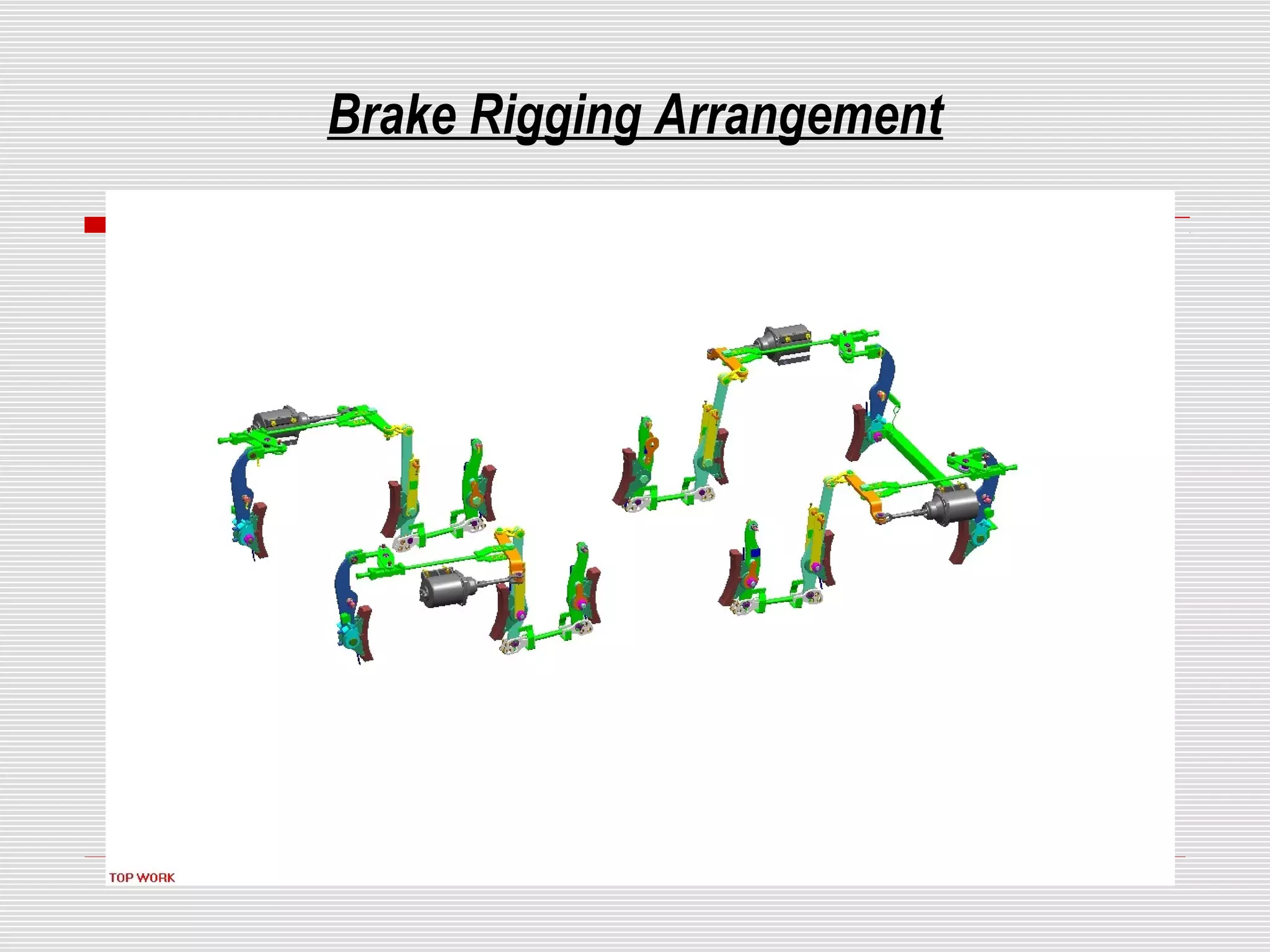
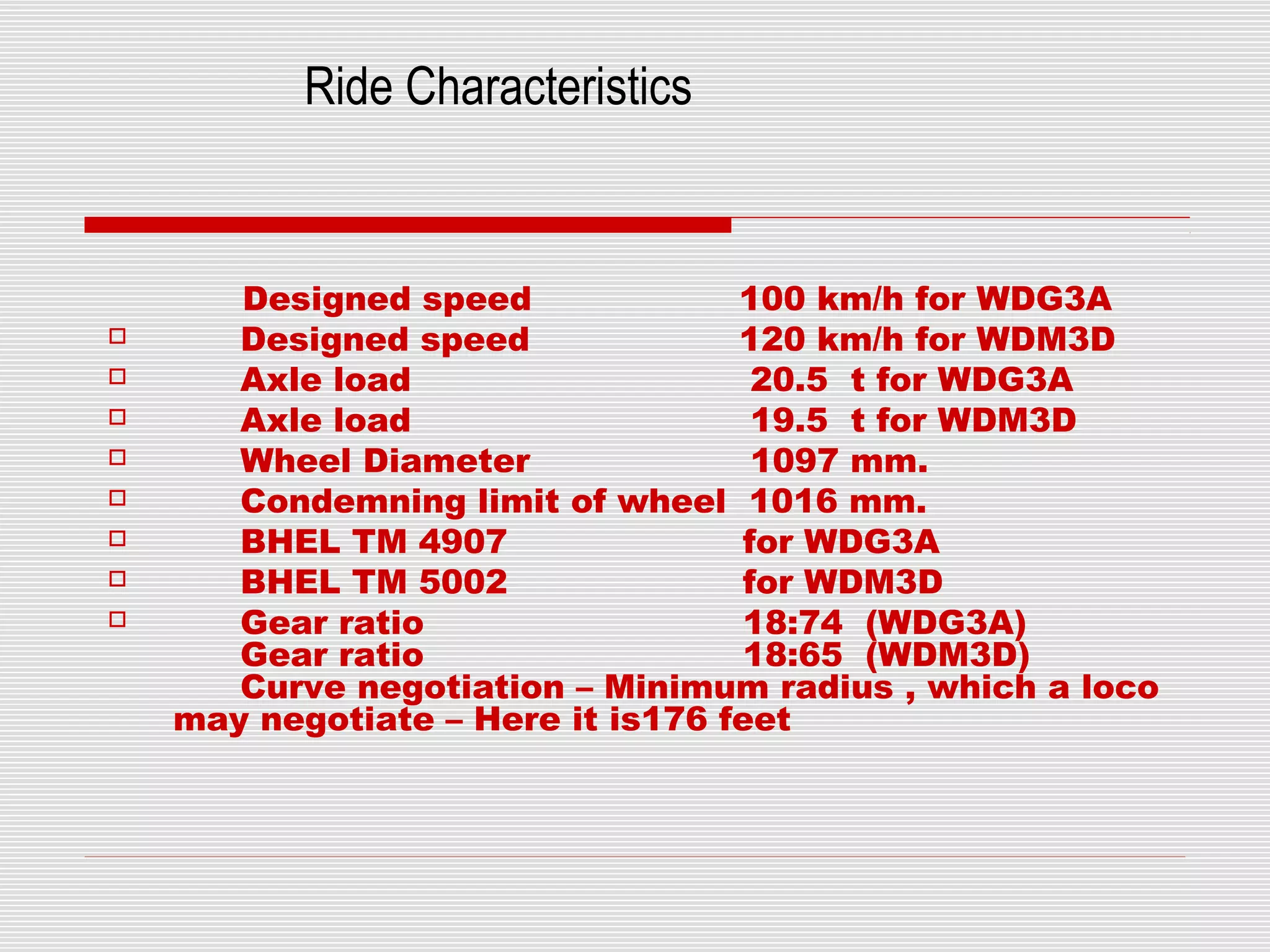


This document provides an overview of bogie assembly for locomotives. It describes that a bogie is a three-axle frame that supports the weight of the locomotive and runs on six wheels. The key components of a bogie include the bogie frame, axles, wheels, traction motors, suspension system, and brake rigging. It then discusses the types of bogies based on wheel arrangement and frame construction, as well as the important parts, suspension arrangement, and ride characteristics.


![52.Shashank internship report[151] (2).pptx](https://cdn.slidesharecdn.com/ss_thumbnails/52-221220220945-ab4dd4e0-thumbnail.jpg?width=640&height=640&fit=bounds)


