This document provides information about cooling system diagnosis and service procedures for a vehicle. It includes:
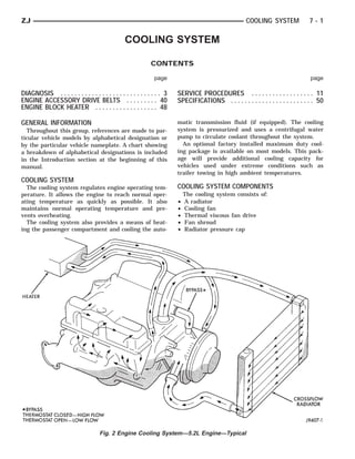
- An overview of cooling system components and coolant routing
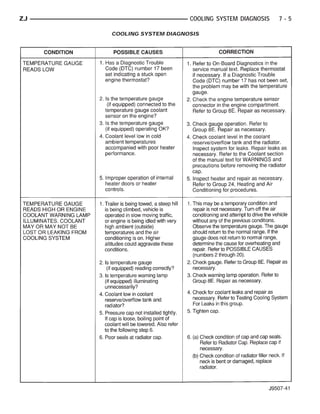
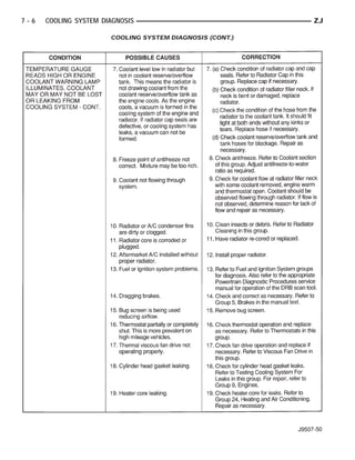
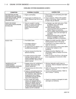
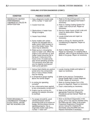
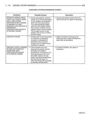
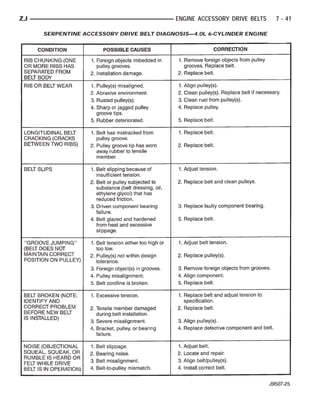
- Diagnosis charts to help identify potential causes of overheating
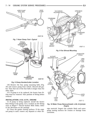
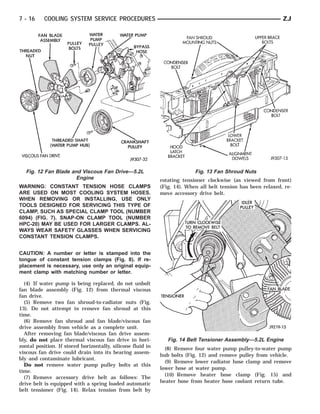
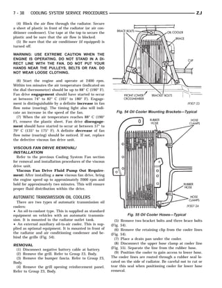
- Procedures for testing the water pump, draining and refilling the cooling system, and replacing components like the radiator, hoses, thermostat, and water pump.
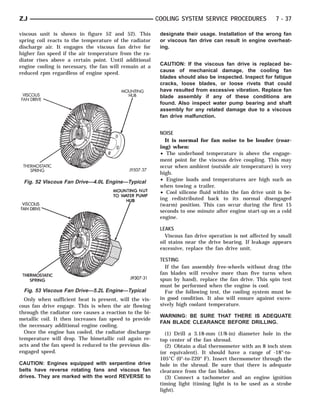
- Cautions for working on the high-pressure cooling system and ensuring the correct rotating water pump is installed.