Downloaded 82 times


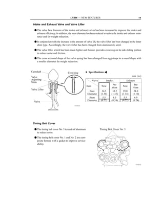
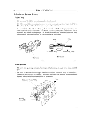
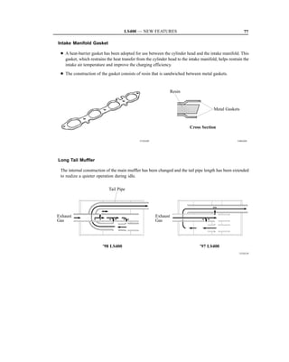
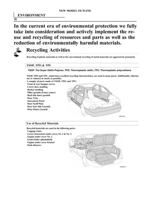
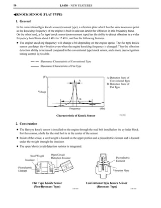
![26 LS400 — NEW FEATURES
F 1UZ–FE ENGINE
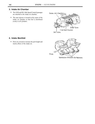
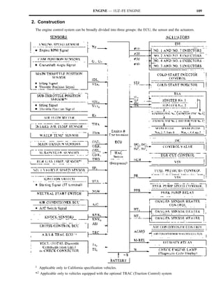
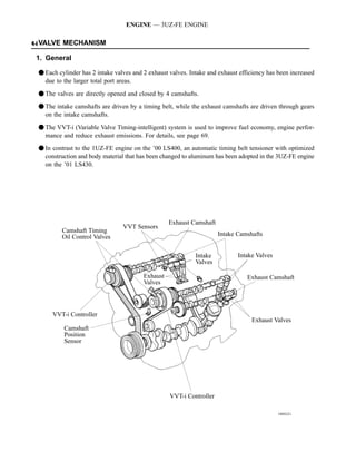
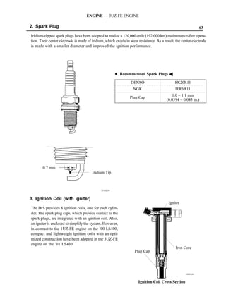
1. General
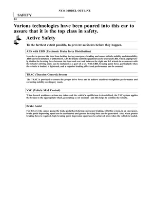
The 1UZ–FE engine of the ’93 LS400 differs from the ’92 LS400 in the following areas:
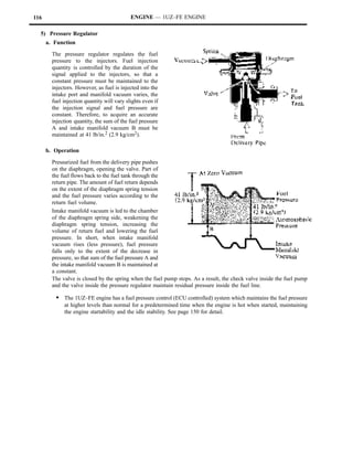
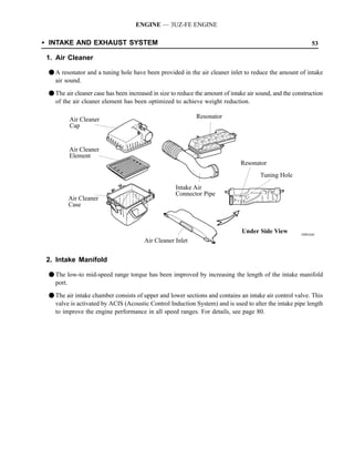
System Outline
Cooling System A newly–developed aluminum radiator is lighter in weight.
Throttle body is made both compact and light (together with the throttle
Intake System
position sensor and IAC* [ISC] valve).
S Fuel injectors are made more compact and light (total length shortened from
Fuel System 78.1 mm to 71 mm [3.07 in. —2.80 in.]).
S Cold start injector has been discontinued.
Engine Control System Refer to 2. Engine Control System table below.
S EGR and EVAP systems are controlled by ECM [engine ECU].
Emission Control System
S Secondary Air Injection system adopted for California–spec vehicles only.
* IAC (Idle Air Control)
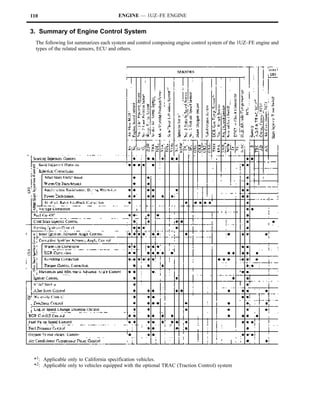
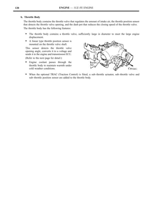
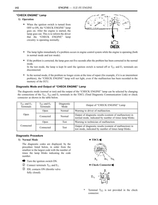
2. Engine Control System
General
The following table shows the comparison of the engine control system of the ’93 LS400’s 1UZ–FE engine to that
of the ’92 LS400:
System Outline ’93 LS400 ’92 LS400
S An L–type MFI [EFI] system directly detects the
intake air volume with an optical Karman–Vortex
MFI*1 [EFI] type volume air flow meter. f f
S The fuel injection system is a 4–group type and
injects to 2 cylinders each.
When starting the engine, the fuel injection system
f —
See Page 29 sprays fuel into all cylinders at the same time.
Cold Start Injector The injection duration of the cold start injector is
controlled by the start injector time switch and — f
Control ECM*2 [ECU].
Ignition timing is determined by the ECM*2 [ECU]
ESA f f
based on signals from various sensors.
A step motor type IAC [ISC] system controls the fast
IAC*3 [ISC] f f
idle and idle speeds.
*1: MFI (Multiport Fuel Injection)
*2: ECM (Engine Control Module)
*3: IAC (Idle Air Control)](https://image.slidesharecdn.com/1uzto3uz-history-130402191653-phpapp01/85/1uzto3uz-history-81-320.jpg)
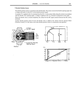
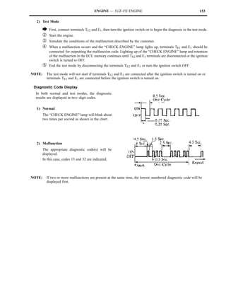
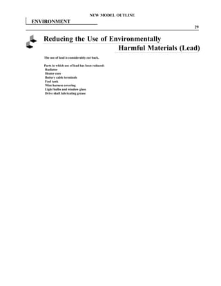
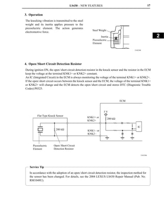
![LS400 — NEW FEATURES 27
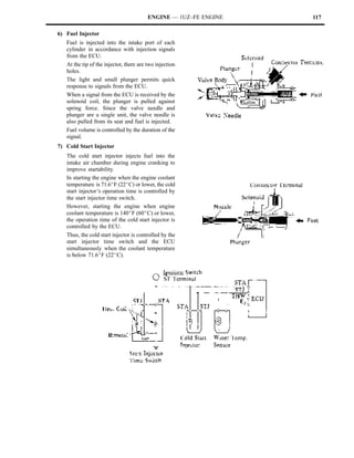
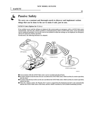
System Outline ’93 LS400 ’92 LS400
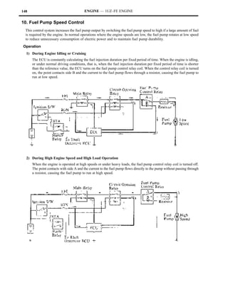
Uses a fuel pump relay
Under light engine loads, — f
Fuel Pump Control
p pump speed is low to and a fuel pump resistor.
reduce electric power Uses fuel pump ECU
loss. f —
(same as ’92 SC400)
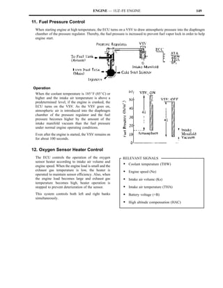
Fuel Pressure Control In hot engine condition, the fuel pressure is increased
f f
to improve restartability.
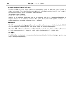
Maintain the temperature of the oxygen sensor at an
Oxygen Sensor
appropriate level to increase accuracy of detection of f f
Heater Control
the oxygen concentration in the exhaust gas.
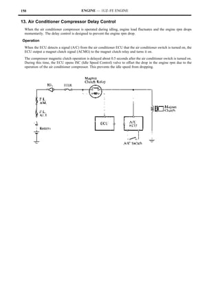
By controlling the air conditioning compressor in
Air Conditioning
accordance with the throttle valve opening angle and f f
Cut–Off Control
the vehicle speed, drivability is maintained.
Cuts off EGR according to the engine condition. — f
EGR Control Drives the EGR valve with step motor, controlling
the EGR volume in accordance with the engine f —
conditions. (same as ’92 SC400)
Controls the purge flow Controlled by TVV*5
of evaporative emissions — f
[BVSV] and VCV
Evaporative (HC) in the charcoal
Emission Control canister in accordance Controlled by ECM
f —
with engine conditions. (same as ’92 SC400)
Secondary Air After staring a cold engine, an electric air pump
Injection Control *4 delivers secondary air to the exhaust system to f —
See Page 30 decrease emissions.
Diagnosis When the ECM detects a malfunction, the ECM
f f
See Page 32 diagnoses and memorizes the failed section.
When the ECM detects a malfunction, the ECM
Fail–Safe
stops or controls the engine according to the data f f
See Page 32
already stored in memory.
*4 California specification vehicles only
*5 TVV (Thermal Vacuum Valve)](https://image.slidesharecdn.com/1uzto3uz-history-130402191653-phpapp01/85/1uzto3uz-history-82-320.jpg)
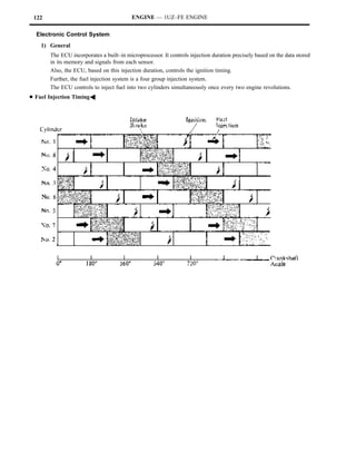
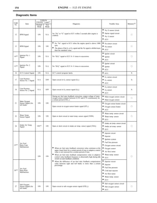
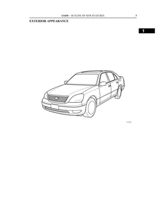
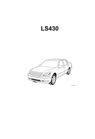
![LS400 — NEW FEATURES 29
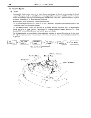
MFI [EFI]
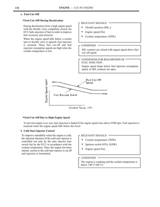
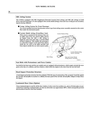
Along with the discontinuing of the cold start injector in the 1UZ–FE engine of the ’93 LS400, the fuel injection
system has been modified as follows, in the starting mode:
1UZ–FE Engine
’93 LS400 ’92 LS400
Engine Condition
Simultaneous injection to all
Engine starting *1 4–Group Type *2
cylinders (every 180_)
Other than starting 4–Group Type 4–Group Type
*1 Engine speed below a predetermined.
*2 The cold start injector will also operate in accordance with the coolant temperature.
DFuel Injection TimingA](https://image.slidesharecdn.com/1uzto3uz-history-130402191653-phpapp01/85/1uzto3uz-history-84-320.jpg)
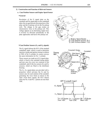
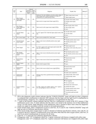
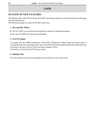
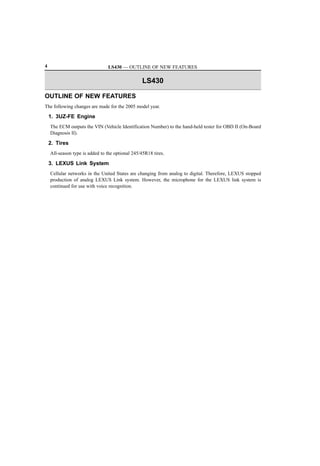
![30 LS400 — NEW FEATURES
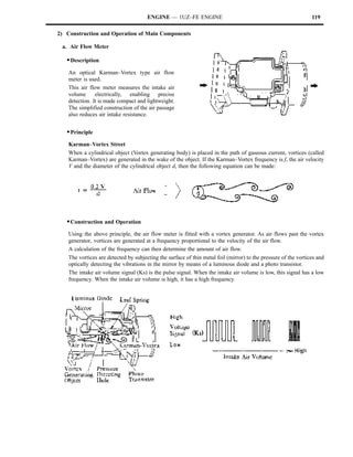
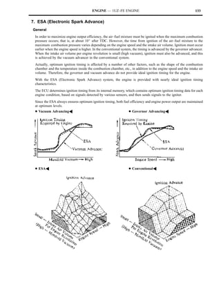
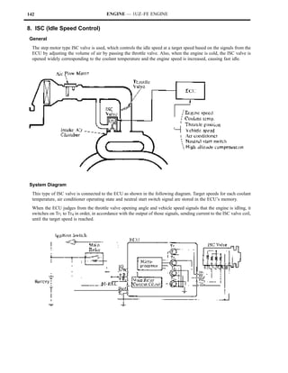
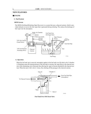
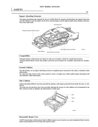
Secondary Air Injection System (California specification vehicles only)
1) General
The Secondary Air Injection is part of the emission control system. It uses an electric air pump controlled by the
ECM [engine ECU] to deliver air to the exhaust system. This will reduce through oxidation the CO and HC
emitted by engine exhaust. Besides the ECM and air pump, this system is comprised of the VSV (Vacuum
Switching Valve), ASV (Air Switching Valve), check valves, etc.](https://image.slidesharecdn.com/1uzto3uz-history-130402191653-phpapp01/85/1uzto3uz-history-85-320.jpg)
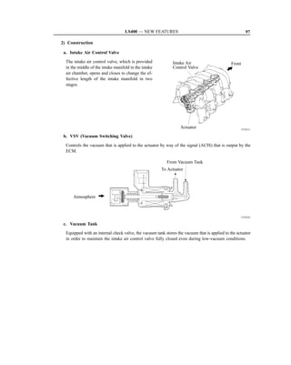
![LS400 — NEW FEATURES 31
2) Construction
a. Electric Air Pump
The air pump is located on the v–bank of the
cylinder block. It is a light and compact
electric (DC motor) air pump which is
controlled by the ECM [engine ECU].
The pressurized air from this pump is sprayed
into the exhaust port after first passing through
the ASV built in the pump. Provided that the
VSV is on, the ASV will remain open by way
of the stored intake manifold pressure.
Electric Air Pump
3) Operation
After starting a cold engine, the ECM engages
the air pump relay to run the air pump. At the
same time, it engages the VSV. Therefore, the
ASV opens under intake manifold pressure,
allowing the secondary air injection to take
place.
RELEVANT SIGNALS
S Engine speed (NE)
S Coolant temperature (THW)
S Volume Air flow meter (Ks)
S Intake air temperature (THA)
S Barometric pressure (HAC)](https://image.slidesharecdn.com/1uzto3uz-history-130402191653-phpapp01/85/1uzto3uz-history-86-320.jpg)
![32 LS400 — NEW FEATURES
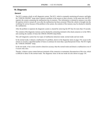
Diagnosis
The diagnostic system of the ’93 LS400 has the following diagnostic trouble codes in addition to those in the ’92
LS400. Code numbers 17 and 18 have been discontinued.
DAdditional Diagnostic Trouble CodesA
Malfunction Indicator
Code Lamp *1
Item Diagnosis Memory *2
No. Normal Test
Mode Mode
All conditions below are detected
continuously for 8 sec. or more.
Vehicle Speed (a) Vehicle speed signal: 0 km/h (mph)
42 OFF ON (b) Engine speed: 2800 rpm or more f
Sensor Signal
(c) Park/Neutral position switch
[Neutral start switch]: OFF
(d) Stop light switch : OFF
Secondary Air
Open or short in VSV circuit of air
48*3 Injection System N.A. N.A. f
switching valve for 5 sec. or more.
Malfunction
(1) Open or short in fuel pump circuit
for 1 sec. or more with engine
speed 1000 rpm or less.
(2) Open in input circuit of fuel pump
78 Fuel Pump OFF ON ECU (FPC) with engine speed f
ControlSignal 1000 rpm or less.
(3) Open or short in diagnostic signal
line (DI) of fuel pump ECU with
engine speed 1000 rpm or less.
*1 : “ON” displayed in the diagnosis mode column indicates that the Malfunction Indicator Lamp [CHECK Engine
Lamp] is lighted up when a malfunction is detected. “OFF” indicates that the “CHECK” does not light up during
malfunction diagnosis, even if a malfunction is detected. “N.A.” indicates that the item is not included in
malfunction diagnosis.
*2 : “f” in the memory column indicates that a diagnostic trouble code is recorded in the ECM [engine ECU] memory
when a malfunction occurs. “x” indicates that a diagnostic trouble code is not recorded in the ECM memory even
if a malfunction occurs.
Accordingly, output of diagnostic results in normal or test mode is performed with the IG switch ON.
*3 : Only for California specification vehicles.
Fail–Safe
In addition to the ’92 LS400 fail–safe functions, the ’93 LS400 has added the electric air pump to the list of abnormal
conditions to be detected.
1) In case of a malfunction in the electric air pump:
When the ECM [engine ECU] detects a problem in the electric air pump by way of the monitor terminals AMTT
and AML+, it will disengage the air pump relay and VSV to stop the secondary air injection.](https://image.slidesharecdn.com/1uzto3uz-history-130402191653-phpapp01/85/1uzto3uz-history-87-320.jpg)
![LS400 — NEW FEATURES 33
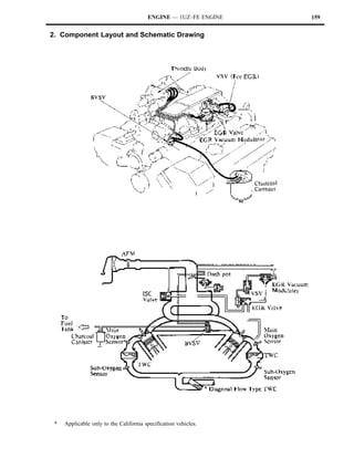
3. Emission Control System
General
The following is a comparison chart of the 1UZ–FE engine emission control system used in the ’93 and ’92 LS400 models:
System Abbreviation ’93 LS400 ’92 LS400
Positive crankcase ventilation PCV f f
Evaporative emission control EVAP f*1 f
Exhaust gas recirculation EGR f*1 f
Three–way catalytic converter TWC f f
Secondary air injection AIR f*1,*2 —
Multiport fuel injection [Electronic fuel injection] MFI [EFI] f f
*1 Controlled by ECM [engine ECU]. See page 26.
*2 California specification vehicles only.
Component Layout and Schematic Drawing](https://image.slidesharecdn.com/1uzto3uz-history-130402191653-phpapp01/85/1uzto3uz-history-88-320.jpg)
![86 APPENDIX — LS400
D LS400
Item Area U.S.A. Canada
Body Type 4–Door Sedan 4–Door Sedan
Vehicle Grade — —
Model Code UCF10L–AEPGKA UCF10L–AEPGKK
Length mm (in.) 4995 (198.7) ←
Overall Width mm (in.) 1830 (72.0) ←
Height mm (in.) 1415 (55.7) ←
Wheel Base mm (in.) 2815 (110.8) ←
Front mm (in.) 1565 (61.6) ←
Thread
Rear mm (in.) 1565 (61.6) ←
Front mm (in.) 980 (38.6), 955 (37.6)*2 ←
Effective Head Room
Rear mm (in.) 935 (36.8), 907 (35.6)*2 ←
Front mm (in.) 1113 ( 48.8) ←
Effective Leg Room
Majo Dime sions & Vehic Weigh s
Major D mensio s Ve icle W ghts
Rear mm (in.) 872 (34.3) ←
Front mm (in.) 1451 (57.1) ←
Shoulder Room
Rear mm (in.) 1430 (56.3) ←
Front mm (in.) 925 (36.4) ←
Overhang
Rear mm (in.) 1255 (49.4) ←
Min. Running Ground Clearance mm (in.) 160 (6.3) ←
Angle of Approach degrees 17, 18 *1 17
Angle of Departure degrees 16, 15*1 16
Front kg (lb) 950 (2095) 970 (2140)
Curb Weight Rear kg (lb) 800 (1765) 810 (1785)
Total kg (lb) 1750 (3860) 1780 (3925)
Front kg (lb) 1075 (2370) ←
Gross Vehicle Weight Rear kg (lb) 1165 (2570) ←
Total kg (lb) 2240 (4940) ←
Fuel Tank Capacity L (U.S. gal, lmp. gal) 85 (22.5, 18.7) ←
Luggage Compartment Capacity m3 (cu.ft) 0.380 (13.42) ←
Max. Speed km/h (mph) 240 (149) ←
Max. Cruising Speed km/h (mph) 215 (134) ←
0 to 100 km/h sec. 7.9 ←
Acceleration
0 to 400 m sec. 15.8 ←
P rforma ce
Perfo mance
1st Gear km/h (mph) 82 (48) ←
2nd Gear km/h (mph) 130 (80) ←
Max.
Max Permissible Speed
3rd Gear km/h (mph) — —
4th Gear km/h (mph) — —
Turning Diameter Wall to Wall m (ft.) 12.0 (39.4) ←
(Outside Front) Curb to Curb m (ft.) 11.0 (36.1) ←
Engine Type 1UZ–FE ←
Valve Mechanism 32–Valve, DOHC ←
Bore x Stroke mm (in.) 87.5 x 82.5 (3.44 x 3.25) ←
Displacement cm3 (cu.in.) 3969 (242.2) ←
Eng e
ngine
Compression 10.0: 1 ←
Carburetor Type MFI [EFI] ←
Research Octane No. RON 96 ←
Max Output (SAE–NET) kW/rpm (HP @ rpm) 186/5600 (250 @ 5600) ←
Max Torque (SAE–NET) N.m/rpm (lb–ft @ rpm) 353/4400 (260 @ 4400) ←
Battery Capacity (20HR) Voltage & Amp. hr. 12–64 ←
ctrical
Electr al
←
gine
Generator Output Watts 1200
Engin
Starter Output kW 2.0 ←
Clutch Type — —
Transmission Type A341E ←
In First 2.531 ←
In Second 1.531 ←
In Third 1.000 ←
Transmission Gear Ratio
In Fourth 0.705 ←
In Fifth — —
In Reverse 1.880 ←
Differential Gear Ratio 3.615 ←
Differential Gear Size in. 8” ←
←
Ch ssis
Front Ventilated Disc
Chassi
Brake Type
Rear Ventilated Disc ←
Parking Brake Type Duo Servo ←
Brake Booster Type and Size in. Tandem 8” + 9” ←
Proportioning Valve Type P & B Valve ←
Front Double Wishbone ←
Suspension Type
Rear Double Wishbone ←
Front STD ←
Stabilizer Bar
Rear STD ←
Steering Gear Type Rack & Pinion ←
Steering Gear Ratio (Overall) 18. : 1 ←
Power Steering Type Integral Type ←
*1: With Air Suspension, *2: With Moon Roof](https://image.slidesharecdn.com/1uzto3uz-history-130402191653-phpapp01/85/1uzto3uz-history-89-320.jpg)

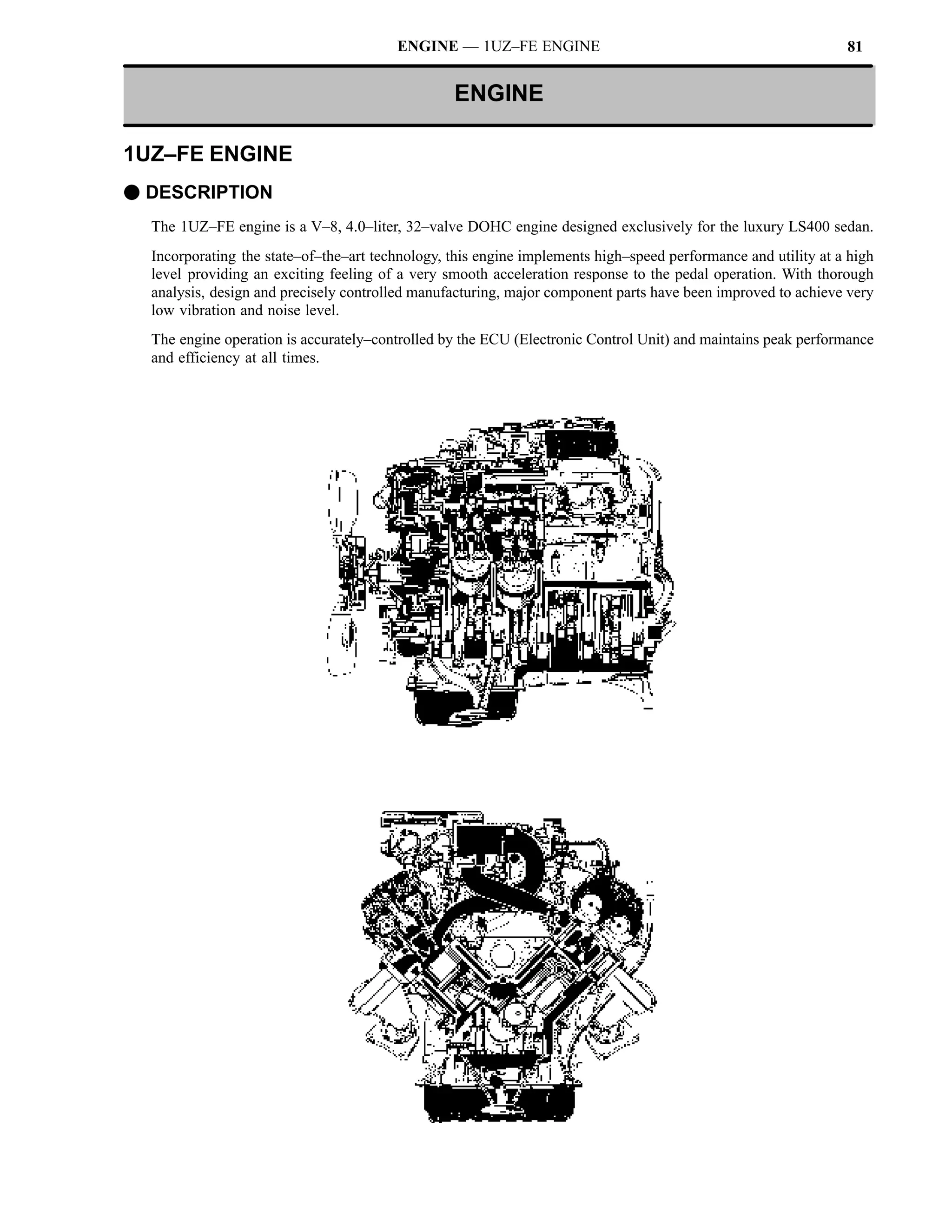
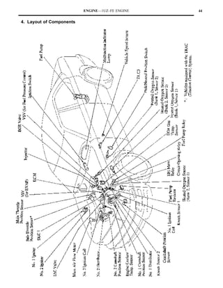
![ENGINE—1UZ–FE ENGINE 36
F ENGINE SPECIFICATIONS AND PERFORMANCE CURVE
1UZ–FE Engine
New Previous
Item
No. of Cyls. & Arrangement 8–Cylinder, V Type ←
Valve Mechanism 32–Valve DOHC, Belt & Gear Drive ←
Combustion Chamber Pentroof Type ←
Manifolds Cross–Flow ←
Fuel System SFI*1 [EFI] MFI*2 [EFI]
Displacement cm3 (cu. in.) 3969 (242.1) ←
Bore x Stroke mm (in.) 87.5 x 82.5 (3.44 x 3.25) ←
Compression Ratio 10.4 : 1 10.0 : 1
194 kW @ 5300 rpm 186 kW @ 5600 rpm
Max. Output [SAE–NET]
(260 HP @ 5300 rpm) (250 HP @ 5600 rpm)
366 N.m @ 4500 rpm 353 N.m @ 4400 rpm
Max. Torque [SAE–NET]
(270 ft.lbf @ 4500 rpm) (260 ft.lbf @ 4400 rpm)
Open 6_ BTDC 3_ BTDC
IN
IN.
Close 46_ ABDC 41_ ABDC
Valve Timing
Open 46_ BBDC ←
EX
EX.
Close 3_ ATDC ←
Fuel Octane Number (RON) 96 ←
API SG, SH, EC–II,
Oil Grade API SH, EC–II, ILSAC*3 or Better
ILSAC*3 or Better
*1: SFI (Sequential Multiport Fuel Injection) *2: MFI (Multiport Fuel Injection)
* 3: ILSAC (International Lubricant Standardization and Approval Committee)](https://image.slidesharecdn.com/1uzto3uz-history-130402191653-phpapp01/85/1uzto3uz-history-91-320.jpg)
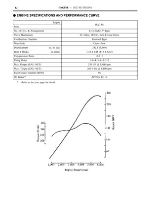
![ENGINE—1UZ–FE ENGINE 38
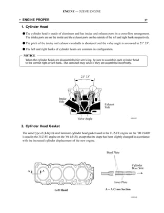
F ENGINE PROPER
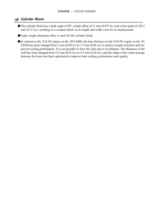
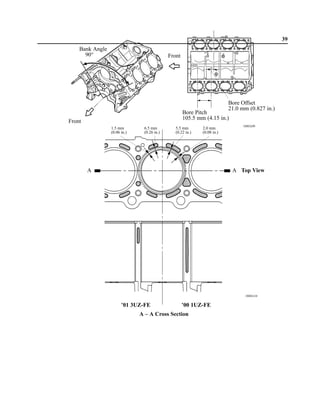
1. Cylinder Block
Passage holes [31 mm (1.22 in.) in diameter] are provided in the crankshaft bearing area of the cylinder block. As
a result, the air at the bottom of the cylinder flows smoother, and pumping loss (back pressure at the bottom of the
piston generated by the piston’s reciprocal movement) is reduced to improve the engine’s output.
DAir Flow During Engine RevolutionA
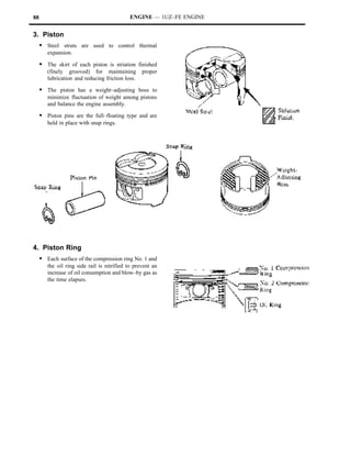
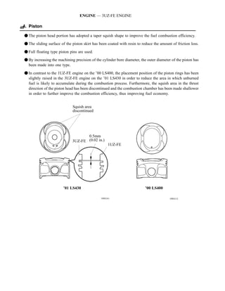
2. Piston
S The piston skirt area is made more compact and lightweight, resulting in reduced friction loss. At the same time,
the skirt rigidity is improved to reduce the noise and vibration.
S The steel strut is discontinued for weight reduction.
S The oil return hole in the oil ring groove is changed from the slot type to slotless type.
S The piston rings are given less tension to reduce friction loss.
S The piston pin is made shorter and thinner for weight reduction. As a result, noise and vibration are reduced.
DPistonA
DPiston PinA](https://image.slidesharecdn.com/1uzto3uz-history-130402191653-phpapp01/85/1uzto3uz-history-93-320.jpg)

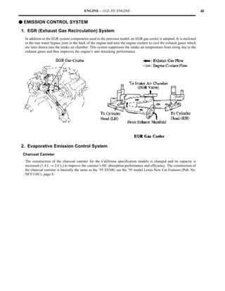
![ENGINE—1UZ–FE ENGINE 40
F ENGINE CONTROL SYSTEM
1. General
The engine control system of the new 1UZ–FE engine is basically the same in construction and operation as that of
the previous 1UZ–FE engine. However, the new 1UZ–FE engine uses a sequential multiport fuel injection system,
and a diagnosis system which conforms to OBD–II.
The engine control system of the new 1UZ–FE engine and previous 1UZ–FE engine are compared below.
System Outline New Previous
An L–type SFI [EFI] system directly detects the intake air
f —
volume with a hot–wire type mass air flow meter.
An L–type MFI*1 [EFI] system directly detects the intake
air volume with an optical Karman–Vortex type volume — f
SFI air flow meter.
(Sequential M lti t
(S ti l Multiport
The fuel injection system is a sequential multiport fuel
Fuel Injection) f —
injection system.
[EFI]
The fuel injection system is a 4–group type and injects to
— f
2 cylinders each.
When starting the engine, the fuel injection system sprays
— f
fuel into all cylinders at the same time.
Ignition timing is determined by the ECM*2 [engine ECU]
based on signals from various sensors. Corrects ignition f f
timing in response to engine knocking.
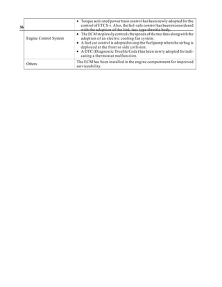
The torque control correction during gear shifting has
ESA f f
(Electronic Spark been used to minimize the shift shock.
Advance) The dwell angle control is implemented by the ECM*2
f —
[engine ECU].
2 knock sensors are used to further improve knock detec-
f f
tion.
IAC (Idle Air Control) A step motor type IAC [ISC] system controls the fast idle
f f
[ISC] and idle speeds.
Uses a fuel pump relay and
Under light engine loads, f —
Fuel Pump Control pump speed is low to reduce a fuel pump resistor.
electric power loss. Uses fuel pump ECU. — f
In hot engine condition, the fuel pressure is increased to
Fuel Pressure Control f f
improve restartability.
Maintains the temperature of the oxygen sensor at an ap-
Oxygen Sensor
propriate level to increase accuracy of detection of the f f
Heater Control
oxygen concentration in the exhaust gas.
*1: MFI (Multiport Fuel Injection)
*2: ECM (Engine Control Module)](https://image.slidesharecdn.com/1uzto3uz-history-130402191653-phpapp01/85/1uzto3uz-history-95-320.jpg)
![41 ENGINE—1UZ–FE ENGINE
System Outline New Previous
By controlling the air conditioning compressor ON or OFF
Air Conditioning
in accordance with the engine condition, drivability is f f
Cut–Off Control
maintained.
Drives the EGR valve with step motor, controlling the
EGR Control f f
EGR volume in accordance with the engine conditions.
The ECM*2 [engine ECU] controls the purge flow of
Evaporative Emission
evaporative emissions (HC) in the charcoal canister in f f
Control
accordance with engine conditions.
When the ECM*2 [engine ECU] detects a malfunction, the
ECM*2 [engine ECU] diagnoses and memorizes the failed f f
section.
Diagnosis The diagnosis system complies with OBD–II. The diagno-
sis items (the failed sections) are discriminated by con-
f —
necting the Lexus hand–held tester to the newly designed
data link connector 3.
When the ECM*2 [engine ECU] detects a malfunction, the
Fail–Safe ECM*2 [engine ECU] stops or controls the engine accord- f f
ing to the data already stored in memory.
*2: ECM (Engine Control Module)](https://image.slidesharecdn.com/1uzto3uz-history-130402191653-phpapp01/85/1uzto3uz-history-96-320.jpg)
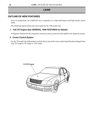
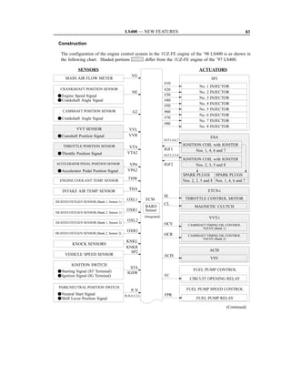
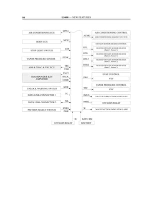
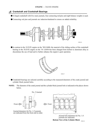
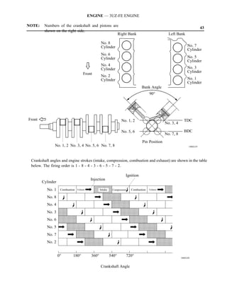
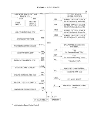
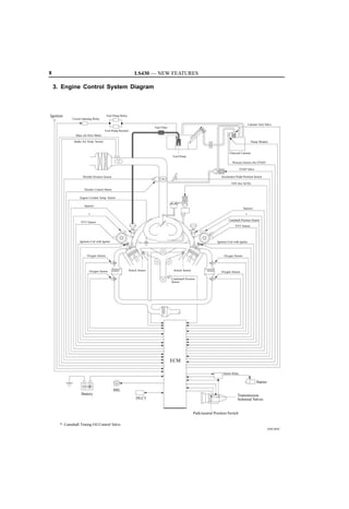
![43 ENGINE—1UZ–FE ENGINE
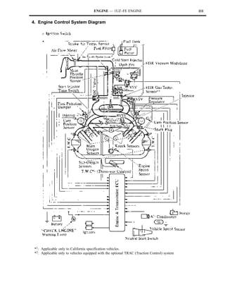
3. Engine Control System Diagram
*1 : ECM (Engine Control Module)
*2 : BARD (Barometric Pressure)
*3 : MIL (Malfunction Indicator Lamp) [Check Engine Lamp]
*4 : DLC 1 & 3 (Data Link Connector 1) [Check Connector], (Data Link Connector 3)
*5 : Vehicles equipped with the TRAC (Traction Control) System](https://image.slidesharecdn.com/1uzto3uz-history-130402191653-phpapp01/85/1uzto3uz-history-98-320.jpg)
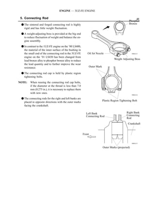
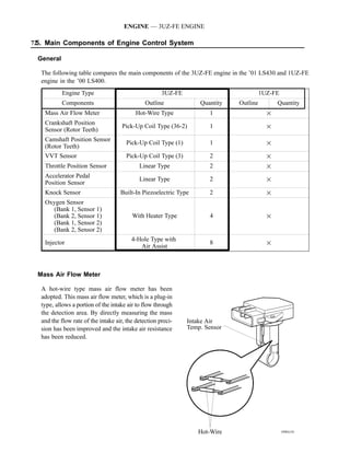
![45 ENGINE—1UZ–FE ENGINE
5. Main Components of Engine Control System
General
The following table compares the main components of the new 1UZ–FE engine and previous 1UZ–FE engine.
1UZ–FE Engine
New Previous
Components
Mass Air Flow Meter Hot–Wire Type —
Volume Air Flow Meter — Karman–Vortex Type
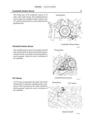
Crankshaft Position Sensor Pick–Up Coil Type, 1 ←
Camshaft Position Sensor Pick–Up Coil Type, 2 ←
Throttle Position Sensor Linear Type ←
Knock Sensor Built–In Piezoelectric Type, 2 ←
Heated Oxygen Sensor
Main Heated Oxygen Sensors
(Bank 1, Sensor 1)
(LH Bank and RH Bank)
Oxygen Sensor (Bank 2, Sensor 1)
Sub–Oxygen Sensors
(Bank 1, Sensor 2)
(LH Bank and RH Bank)
(Bank 2, Sensor 2)
Injector 2–Hole Type ←
IAC [ISC] Valve Step Motor Type ←
Mass Air Flow Meter
The hot–wire type mass air flow meter is designed for direct electrical measurement of the intake air mass flow. It
has the following features:
S Compact and lightweight
S Ability to measure a wide intake air mass flow
S Superior response and measuring accuracy
S Having no mechanical functions, it offers superior durability.
For details of the principle and operation of the hot–wire type mass air flow meter, see the ’94 model Lexus New Car
Features (Pub. No. NCF098U), page 33.](https://image.slidesharecdn.com/1uzto3uz-history-130402191653-phpapp01/85/1uzto3uz-history-100-320.jpg)
![ENGINE—1UZ–FE ENGINE 46
6. SFI (Sequential Multiport Fuel Injection) [EFI]
In place of the L–type MFI (Multiport Fuel Injection) [EFI] system with an optical Karman–Vortex type volume air
flow meter used in the previous 1UZ–FE engine, the new 1UZ–FE engine uses the L–type SFI [EFI] system with a
hot–wire type mass air flow meter. Compared to the previous 1UZ–FE engine, the new 1UZ–FE engine with SFI [EFI]
offers the following characteristics:
S Adopts a hot–wire type mass air flow meter with superior measuring precision.
S In place of the 4–group type fuel injection pattern used by the previous 1UZ–FE engine, the new 1UZ–FE adopts
a sequential multiport fuel injection type pattern.
Fuel Injection Pattern and Fuel Injection Timing
The new 1UZ–FE engine adopts a sequential multiport fuel injection system in which the air–fuel mixture is
introduced into each cylinder every time the engine completes two revolutions. It also optimally regulates the
injection timing according to the engine condition.
7. ESA (Electronic Spark Advance)
The ESA system of the new 1UZ–FE engine is basically the same in construction and operation as that of the previous
1UZ–FE engine. However, the dwell angle control which was executed by the igniter is now implemented by the
ECM* [engine ECU] in the new model.
8. IAC (Idle Air Control) [ISC]
The IAC system of the new 1UZ–FE engine is basically the same in construction and operation as that of the previous
1UZ–FE engine. However, the new 1UZ–FE engine uses an electrical load estimate correction function. The target
idle speed thus varies according to electrical loads such as taillights or rear window defogger.
9. Fuel Pump Control
As in the 1UZ–FE engine of the previous models, this system switches the fuel pump speed between high and low
speed according to engine conditions, reducing the electrical load. However, in the new 1UZ–FE engine, the fuel
pump speed switching components has been changed from the fuel pump control ECU to fuel pump control relay and
resistor. This system is basically the same as that used in the 1UZ–FE engine of the ’91 LS400. For details, see ’90
LS400 New Car Features (Pub. No. NCF054U) on page 148.
10.Diagnosis
The diagnosis system of the new 1UZ–FE engine complies with OBD–II. For OBD–II requirements, see ’94 model
Lexus New Car Features (Pub. No. NCF098U), page 2. For details of the following items, refer to the ’95 LS400
Repair Manual (Pub. No. RM405U1).
Item Contents
Data Link Connector Data Link Connector 3 added for OBD–II.
Perform by connecting the Lexus hand–held tester to Data Link
Diagnostic Trouble Code Check Method
Connector 3.
Diagnostic Trouble Code —
ECM* [Engine ECU] Memory Items Freezed frame data added.
*: ECM (Engine Control Module)](https://image.slidesharecdn.com/1uzto3uz-history-130402191653-phpapp01/85/1uzto3uz-history-101-320.jpg)
![47 ENGINE—1UZ–FE ENGINE
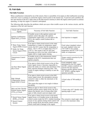
11.Fail–Safe
The fail–safe functions of the new 1UZ–FE engine are as follows:
Circuit with Abnormal Signals Fail–Safe Function
Fixed values (standard values) based on the condition of the STA
Mass Air Flow Meter Signal (VG) signal and IDL contacts are used for the fuel injection duration and
the ignition timing (5_ BTDC), making engine operation possible.
Engine Coolant Temp. Sensor Fixed value (standard value) is used: 80_C (176_F) for engine
[Water Temp. Sensor] Signal (THW) coolant temp.
Fixed value (standard value) is used: 20_C (68_F) for intake air
Intake Air Temp. Sensor Signal (THA)
temp.
Barometric Pressure Sensor
[High Altitude Compensation Sensor] Fixed value of 760 mmHg is used.
Signal (HAC)
Main and Sub Throttle Position Sensor
A fixed value of 0_ throttle valve opening angle is used.
Signal (VTA1, 2)
S Knock Sensor Signal (KNK1, 2)
The corrective retard angle value is set to the maximum value.
S Knock Control System
Ignition Confirmation Signal (IGF1, 2) Fuel injection is stopped.](https://image.slidesharecdn.com/1uzto3uz-history-130402191653-phpapp01/85/1uzto3uz-history-102-320.jpg)
![161 APPENDIX
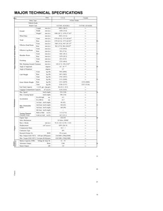
MAJOR TECHNICAL SPECIFICATIONS
Item Area U.S.A. Canada
Body Type 4 Door Sedan
Vehicle Grade — —
Model Code UCF20L–AEPGKA UCF20L–AEPGKK
Length mm (in.) 4995 (196.7) ←
Overall Width mm (in.) 1830 (72.0) ←
Height mm (in.) 1420 (55.9) ←
Wheel Base mm (in.) 2850 (112.2) ←
Front mm (in.) 1575 (62.0) ←
Tread
Rear mm (in.) 1575 (62.0) ←
Front mm (in.) 989 (38.9), 965 (37.9)*1 ←
Effective Head Room
Rear mm (in.) 938 (36.9), 907 (35.7)*1 ←
Front mm (in.) 1109 (43.7) ←
Effective Leg Room
Major D mensio s Ve icle W ghts
Majo Dime sions & Vehic Weigh s
Rear mm (in.) 938 (36.9) ←
Front mm (in.) 1470 (57.9) ←
Shoulder Room
Rear mm (in.) 1450 (57.1) ←
Front mm (in.) 900 (35.4) ←
Overhang
Rear mm (in.) 1245 (49.0) ←
Min. Running Ground Clearance mm (in.) 140 (5.5), 135 (5.3)*2 140 (5.5)
Angle of Approach degrees 15 ←
Angle of Departure degrees 16, 15*2 16
Front kg (lb) 910 (2005) 920 (2028)
Curb Weight Rear kg (lb) 745 (1645) 755 (1664)
Total kg (lb) 1655 (3650) 1675 (3692)
Front kg (lb) 1050 (2315) 1030 (2271)
Gross Vehicle Weight Rear kg (lb) 1105 (2435) 1105 (2436)
Total kg (lb) 2155 (4750) 2135 (4707)
Fuel Tank Capacity L (U.S. gal., Imp. gal.) 85 (22.5, 18.7) ←
Luggage Compartment Capacity m3 (cu. ft.) 0.41 (14.6) ←
Max. Speed km/h (mph) 240 (149) ←
Max. Cruising Speed km/h (mph) 215 (134) ←
0 to 100 km/h sec. — —
Acceleration
0 to 400 m sec. 15.2 ←
P rforma ce
Perfo mance
1st Gear km/h (mph) 73 (45) ←
2nd Gear km/h (mph) 134 (83) ←
Max.
Max Permissible Speed
3rd Gear km/h (mph) — —
4th Gear km/h (mph) — —
Turning Diameter Wall to Wall m (ft.) 11.4 (37.4) ←
(Outside Front) Curb to Curb m (ft.) 10.6 (34.8) ←
Engine Type 1UZ–FE ←
Valve Mechanism 32 Valve, DOHC ←
Bore x Stroke mm (in.) 87.5 x 82.5 (3.44 x 3.25) ←
Displacement cm3 (cu. in.) 3969 (242.1) ←
Eng e
ngine
Compression Ratio 10.4 : 1 ←
Carburetor Type SFI ←
Research Octane No. RON 96 ←
Max. Output (SAE–NET) kW/rpm (HP @ rpm) 194/5300 (260@5300) ←
Max. Torque (SAE–NET) N.m/rpm (lb–ft @ rpm) 366/4500 (270@4500) ←
Battery Capacity (5HR) Voltage & Amp. hr. 12–55 ←
ctrical
Electr al
←
gine
Generator [Alternator] Output Watts 960
Engin
Starter Output kW 2.0 ←
Clutch Type — —
Transmission Type A340E ←
In First 2.804 ←
In Second 1.531 ←
In Third 1.000 ←
Transmission Gear Ratio
In Fourth 0.705 ←
In Fifth — —
In Reverse 2.393 ←
Differential Gear Ratio 3.615 ←
Differential Gear Size in. 8” ←
←
Ch ssis
Front Ventilated Disc
Chassi
Brake Type
Rear Ventilated Disc ←
Parking Brake Type Duo Servo ←
Brake Booster Type and Size in. Tandem, 8” + 9” ←
Proportioning Valve Type — —
Front Double Wishbone ←
Suspension Type
Rear Double Wishbone ←
Front STD ←
Stabilizer Bar
Rear STD ←
Steering Gear Type Rack & Pinion ←
Steering Gear Ratio (Overall) 18.7 : 1 ←
Power Steering Type Integral Type ←
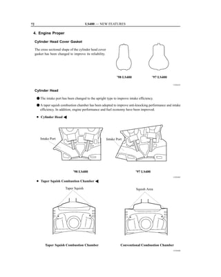
*1 : with Air Suspension
*2 : with Moon Roof](https://image.slidesharecdn.com/1uzto3uz-history-130402191653-phpapp01/85/1uzto3uz-history-104-320.jpg)

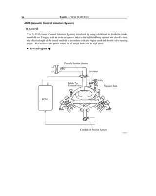
![LS400 — NEW FEATURES 69
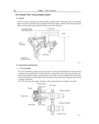
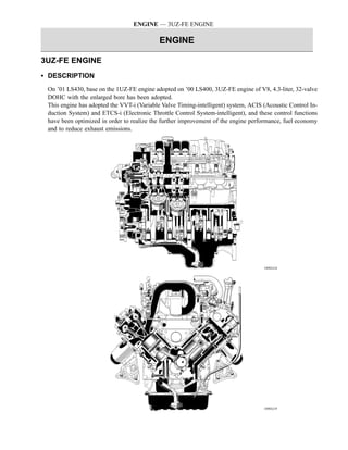
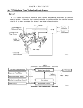
D1UZ-FE ENGINE
1. Description
The 1UZ-FE engine has adopted the VVT-i (Variable Valve Timing-intelligent) system and the ACIS (Acous-
tic Control Induction System) to improve engine performance and fuel economy and to reduce exhaust
emissions.
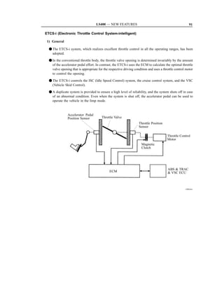
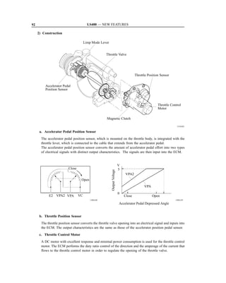
In addition, it has adopted the ETCS-i (Electronic Throttle Control System-intelligent) to ensure excellent
controllability of the vehicle and to improve its comfort.
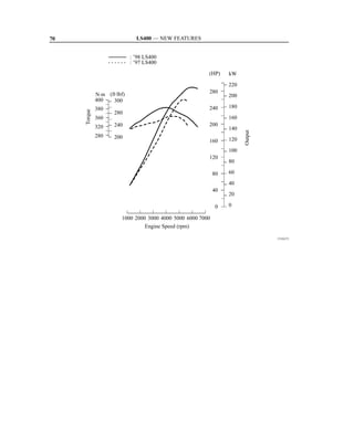
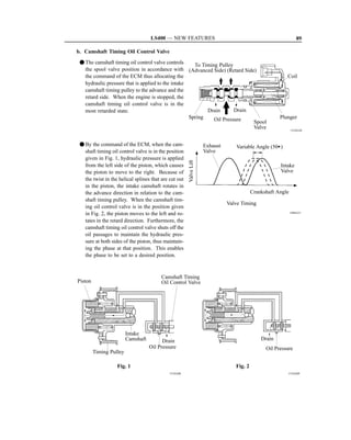
2. Engine Specifications and Performance Curve
1UZ-FE Engine
’98 LS400 ’97 LS400
Item
No. of Cyls. & Arrangement 8-Cylinder, V Type z
32-Valve DOHC,
Valve Mechanism z
Belt & Gear Drive
Combustion Chamber Pentroof Type z
Manifolds Cross-Flow z
Fuel System SFI z
Displacement cm3 (cu. in.) 3969 (242.1) z
BoreStroke mm (in.) 87.582.5 (3.443.25) z
Compression Ratio 10.5 : 1 10.4 : 1
216 kW @ 6000 rpm 194 kW @ 5300 rpm
Max. Output [SAE-NET]
(290HP @ 6000rpm) (260HP @ 5300 rpm)
407 N!m @ 4000 rpm 366 N!m @ 4500 rpm
Max. Torque [SAE-NET]
(300 ft!lbf @ 4000 rpm) (270 ft!lbf @ 4500 rpm)
Open –14A~36A BTDC 6A BTDC
Intake
Valve Close 64A~14A ABDC 46A BTDC
Timing Open 46A BBDC z
Exhaust
Close 3A ATDC z
Fuel Octane Number (RON) 96 z
Oil Grade API SH EC-II, SJ EC or ILSAC API SH EC-II or ILSAC](https://image.slidesharecdn.com/1uzto3uz-history-130402191653-phpapp01/85/1uzto3uz-history-108-320.jpg)


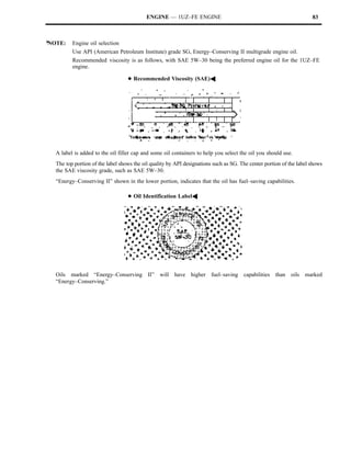
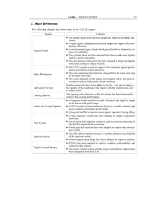
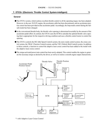
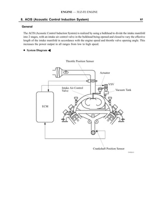
![ENGINE — 3UZ-FE ENGINE
34 D Engine Specifications A
Engine Type 3UZ-FE 1UZ-FE
No. of Cyls. Arrangement 8-Cylinder, V Type !
32-Valve DOHC,
Valve Mechanism !
Belt Gear Drive
Combustion Chamber Pentroof Type !
Manifolds Cross-Flow !
Fuel System SFI !
Displacement cm3 (cu. in.) 4293 (261.9) 3969 (242.1)
Bore × Stroke mm (in.) 91.0 × 82.5 (3.58 × 3.25) 87.5 × 82.5 (3.44 × 3.25)
Compression Ratio 10.5 : 1 !
216 kW @ 5600 rpm 216 kW @ 6000 rpm
Max. Output [SAE-NET]
(290 HP @ 5600 rpm) (290 HP @ 6000 rpm)
434 N⋅m @ 3400 rpm 407 N⋅m @ 4000 rpm
Max. Torque [SAE-NET]
(320 ft⋅lbf @ 3400 rpm) (300 ft⋅lbf @ 4000 rpm)
Open –14° ~ 31° BTDC –14° ~ 36° BTDC
Intake
Close 64° ~ 19° ABDC 64° ~ 14° ABDC
Valve Timing
Open 46° BBDC !
Exhaust
Close 3° ATDC !
Fuel Octane Number RON 95 or more !
Oil Grade API SJ, EC or ILSAC !
D Performance Curve A
(HP) KW
N·m (ft·lb) 300 220
480 360 280
200
440 260
320
240 180
Torque 400
280
360 220 160
320 240 200
140
180
280 200
160 120
Output
140
100
120
80
100
80 60
60
40
40
20
20
0
1000 2000 3000 4000 5000 6000 7000
189EG20
Engine Speed (rpm)](https://image.slidesharecdn.com/1uzto3uz-history-130402191653-phpapp01/85/1uzto3uz-history-140-320.jpg)


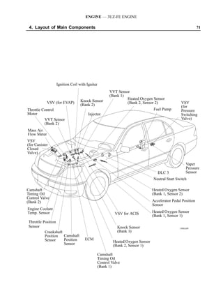


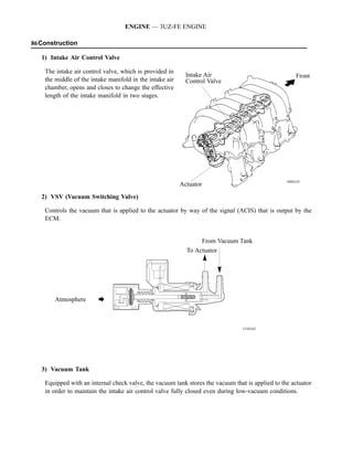


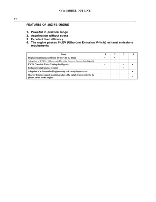
![NEW MODEL OUTLINE
MECHANISM
21
Obsessed with superior performance, as well as con-
cern for the environment.
The LS430 contains limitless possibilities.
Engine
The V8 4.3L 3UZ-FE engine has been adopted.
The V8 4.3L 3UZ-FE engine developed through the incorporation of the latest technology, achieving an improve-
ment in total performance by enlarging the bore, based on the 1UZ-FE engine installed in the previous LS400,
and improvements of other engine parts.
This engine turns smoothly and runs dynamically. With the VVT-i (Variable Valve Timing-intelligent) system, ACIS
(Acoustic Control Induction System), ETCS-i (Electronic Throttle Control System-intelligent) and optimal utilization
of their control functions, excellent engine performance is ensured. The engine features good fuel economy, clean ex-
haust gas performance, and is packed with superior performance features that are just what you would expect from
an engine mounted on the LEXUS flagship.
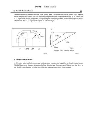
D Outline of the 3UZ-FE Engine A
Overall Engine Displacement cm3 (cu.in.) 4,293 (261.9)
Bore × Stroke mm (in.) 91 × 82.5 (3.58 × 3.259)
216 kW @ 5,600 rpm
Maximum Output [SAE-NET]
(290 HP @ 5,600 rpm)
434 N·m @ 3,400 rpm
Maximum Torque [SAE-NET]
(320 ft·lbf @ 3,400 rpm)
D Performance Curve A
(HP) KW
N·m (ft·lb) 300 220
480 360 280
200
440 260
320
240 180
Torque 400
280
360 220 160
320 240 200
140
180
280 200
160 120
140
100
120
80
100
80 60
60
40
40
20
20
0
1000 2000 3000 4000 5000 6000 7000
189EG20
Engine Speed (rpm)](https://image.slidesharecdn.com/1uzto3uz-history-130402191653-phpapp01/85/1uzto3uz-history-204-320.jpg)


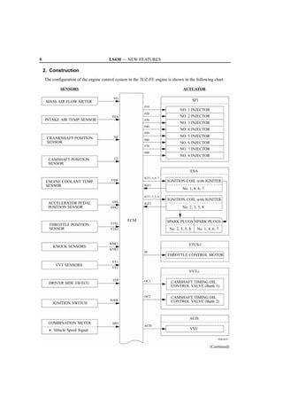
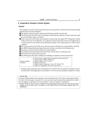
![4 LS430 — NEW FEATURES
NEW FEATURES
D3UZ-FE ENGINE (ENGINE CONTROL SYSTEM)
1. General
The engine control system of the 3UZ-FE engine on the ’06 LS430 has the following system.
Model
System Outline
’06 Model ’05 Model
SFI
An L-type SFI system directly detects the intake air mass with
Sequential Multiport A A
Fuel Injection a hot wire type mass air flow meter.
ESA Ignition timing is determined by the ECM based on signals
Electronic Spark from various sensors. The ECM corrects ignition timing in A A
Advance response to engine knocking.
ETCS-i Optimally controls the throttle valve opening in accordance
Electronic Throttle
with the amount of accelerator pedal effort and engine and A A
Control
vehicle conditions.
System-intelligent
VVT-i
Controls the intake camshaft to optimal valve timing in
Variable Valve A A
accordance with the engine condition.
Timing-intelligent
ACIS The intake air passages are switched according to the engine
Acoustic Control speed and throttle valve opening angle to provided high A A
Induction System performance in all speed ranges.
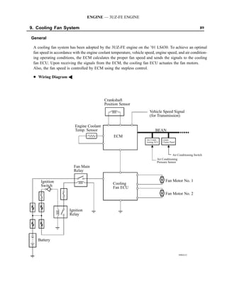
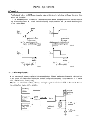
The ECM steplessly controls the speed of the fans in
accordance with the engine coolant temperature, vehicle
Cooling Fan Control A A
speed, engine speed, and air conditioning operation
conditions.
• The ECM controls fuel pump speed by switching the circuit
to the fuel pump resistor.
Fuel Pump Control A A
• The fuel pump is stopped, when the SRS airbag is deployed
in front, side, or rear side collision.
Maintains the temperature of the oxygen sensor at an
Oxygen Sensor
appropriate level to increase accuracy of detection of the A A
Heater Control oxygen concentration in the exhaust gas.
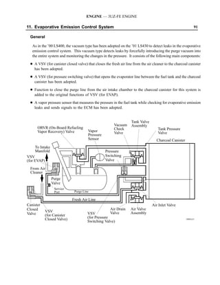
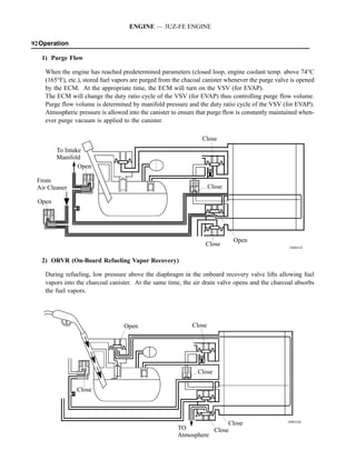
The ECM controls the purge flow of evaporative emission
(HC) in the charcoal canister in accordance with engine A A
conditions.
Using three VSVs and a vapor pressure sensor, the ECM
detects any evaporative emission leakage occurring between
Evaporative Emission — A
the fuel tank and the charcoal canister through pressure
Control
[See page 9] changes in the fuel tank.
Approximately five hours after the ignition switch has been
turned OFF, the ECM operates the leak detection pump to
detect any evaporative emission leakage occurring between A —
the fuel tank and the charcoal canister through pressure
changes in the fuel tank.
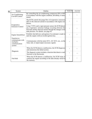
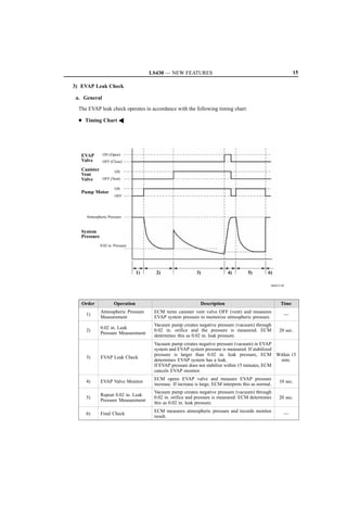
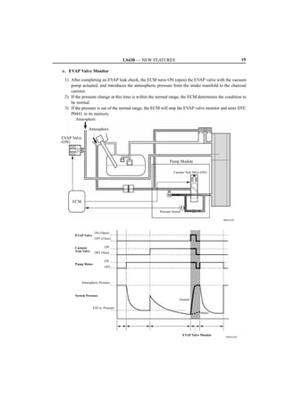
(Continued)](https://image.slidesharecdn.com/1uzto3uz-history-130402191653-phpapp01/85/1uzto3uz-history-220-320.jpg)
![LS430 — NEW FEATURES 5
Model
System Outline
’06 Model ’05 Model
Air Conditioning By turning the A/C compressor ON or OFF in accordance with
A A
Cut-off Control the engine condition, drivability is maintained.
Prohibits fuel delivery and ignition if an attempt is made to
Engine Immobilizer A A
start the engine with an invalid ignition key.
Diagnosis When the ECM detects a malfunction, the ECM diagnoses and
A A
[See page 21] memorizes the failed section.
When the ECM detects a malfunction, the ECM stops or
Fail-safe controls the engine according to the data already stored in the A A
memory.](https://image.slidesharecdn.com/1uzto3uz-history-130402191653-phpapp01/85/1uzto3uz-history-221-320.jpg)
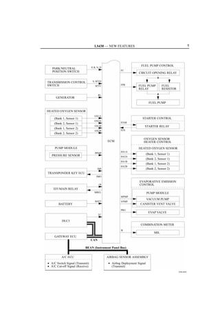
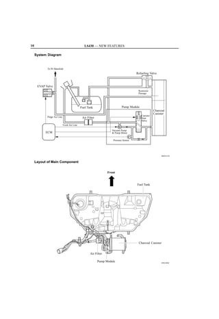
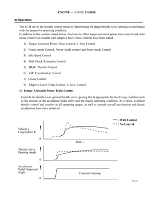
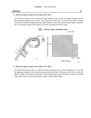
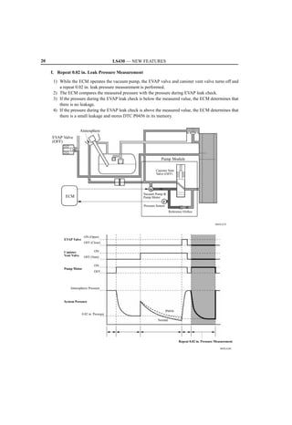
![LS430 — NEW FEATURES 13
3) Pump module
Pump module consists of the canister vent valve, pressure sensor, vacuum pump, and pump motor.
F The canister vent valve switches the passages in accordance with the signals received from the ECM.
F A DC type brushless motor is used for the pump motor.
F A vane type vacuum pump is used.
Canister Vent Valve
Fresh Air
Fresh Air Pressure Sensor
Pump Motor
Vacuum Pump
Pressure Sensor
D13N15
Charcoal Canister
D13N16
D Simple Diagram A
Pump Module
Canister Vent
Valve (OFF)
Fresh Air
Filter
To Charcoal
M Canister
Vacuum Pump
Pump Motor
P
Pressure Sensor Filter
Reference Orifice
[0.5 mm, (0.020 in.) Diameter]
060XA16C](https://image.slidesharecdn.com/1uzto3uz-history-130402191653-phpapp01/85/1uzto3uz-history-229-320.jpg)

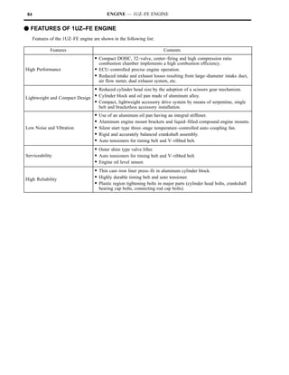
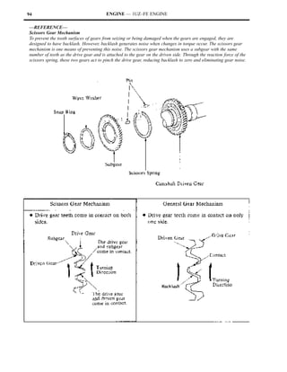
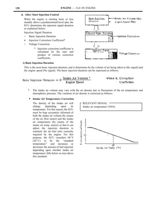
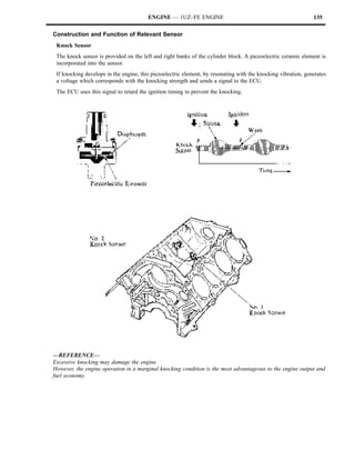
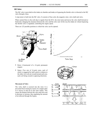
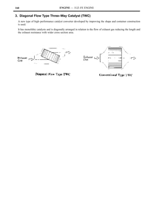
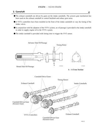
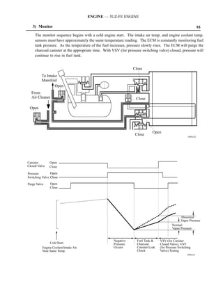
The 1UZ-FE engine is a 4.0-liter V8 with 32 valves and DOHC design. It produces 250 horsepower at 5,600 rpm and 260 ft-lbs of torque at 4,400 rpm. Key features include a compact design achieved through a scissors gear mechanism and lightweight materials, low noise and vibration, and high reliability ensured by features like plastic tightening bolts. The engine is controlled by an ECU to maintain peak performance and efficiency.