The document provides specifications for an apparatus used to measure the length change of hardened cement paste, mortar, and concrete. It describes the construction, dimensions, materials, and markings required for a length comparator, which uses a micrometer to measure the change in length of specimens against a reference bar. The length comparator consists of an adjustable frame that holds either a screw or dial micrometer and allows measurement of specimens of different lengths.
USE OF CFRP LAMINATES FOR STRENGTHENING OF REINFORCED CONCRETE CORBELSIAEME Publication
This work consists of fabrication and testing of sixteen reinforced concrete corbels. Fourteen of these corbels have been strengthened or repaired by various plies of Carbon Fiber Reinforced Polymer (CFRP) laminates. The experimental variables considered in the test program include, the CFRP pattern scheme (i.e. location, orientation, and number of layers), bond type (partial warping, full warping, and using CFRP anchors), and damaged ratio. Two modes of failure were observed, debonding and rupture of the CFRP laminates. Significant increase in ultimate capacity ranging from 17% to 71% was registered in the strengthening specimens and from 13% to 65% in repaired specimens.
Experimental Observation on Reduction of Foot Formation of 4600-M Aluminum Al...ijsrd.com
Formation of foot occurs in shaping when a cutting tool exits the work piece. It may cause chipping of the cutting edge leaving the exit edge of the work piece. Presence of foot causes difficulties in the manufacture of different assembly. In this experiment, an attempt is made to reduce foot formation of aluminum alloy (4600-M) by beveling the exit edge of the work piece under dry environment. Experimental results are analyzed through ANOVA to find out the significance of machining parameters and exit edge bevel angle to reduce foot formation. It is found out that exit edge bevel angle has more significant effect than cutting velocity and orthogonal rake angle. No foot is observed at 15 ° exit edge bevel angle.
International Journal of Engineering Research and Applications (IJERA) is an open access online peer reviewed international journal that publishes research and review articles in the fields of Computer Science, Neural Networks, Electrical Engineering, Software Engineering, Information Technology, Mechanical Engineering, Chemical Engineering, Plastic Engineering, Food Technology, Textile Engineering, Nano Technology & science, Power Electronics, Electronics & Communication Engineering, Computational mathematics, Image processing, Civil Engineering, Structural Engineering, Environmental Engineering, VLSI Testing & Low Power VLSI Design etc.
Experimental Evaluation of Metal Composite Multi Bolt Radial Joint on Laminat...IJERA Editor
Longitudinal tensile load exerted due to internal hydraulic pressure, on bolted radial joints between large size PAN carbon epoxy filament wound composite cylindrical section and small size 15CDV6 steel cylindrical sections, were simulated and tested on flat laminate level, mainly to check the strength of PAN carbon epoxy helical wound laminate made by wet winding method. Small segmental portion of circumference of cylindrical sections was considered as width of composite laminate and of metallic plates, necessary to accommodate 5 rows of fasteners in transverse direction with specified pitch distance. Bolted radial joints between carbon epoxy helical wound flat laminate and 15CDV6 steel plates were realized with 8 numbers of steel fasteners distributed in 3 longitudinal and 5 transverse rows at each joint. Helical angle of winding, length and thickness of carbon epoxy laminate was ±22.5°, 458mm and 11mm respectively. Length and structural thickness of radial joints, total length and width of assembly test specimen were 98mm, 18mm, 870mm and 169.43mm respectively. Joints were tested under uni-axial tensile load up to failure. Joints failed at 18 tonnes (1.7 times of design load). Failure mode was observed as initiation of bearing failure at all 8, countersink fastener holes in laminate and shear out failure at edge hole. Strains in fibre direction, at 45°and at transverse to fibre direction were found very less. Maximum compressive strain and residual strain, near fastener holes were found as -1423 and -136 micro strain respectively. Test was successful.
Micro-structural and Tribological Behaviour of AA6063/12SiC-5Gr Hybrid Compos...ijsrd.com
In this paper the friction and wear behavior of aluminium matrix reinforced with silicon carbide and graphite is investigated. A pin on disc type apparatus is used to measure the sliding wear rate (WR), the frictional force (F) and the coefficient of friction (μ). Friction and wear behavior of the hybrid metal matrix composites (HMMC) have been investigated at various loads, sliding velocity and constant sliding distance. The applied loads are 20N, 40N, 60N and 80 N respectively, sliding speeds are 1.5 m/sec and 3 m/sec and the sliding distance is 1500 m. The aluminium based MMC has been produced by stir casting technique. AA6063 with 12SiC-5Gr composite is machined to the required size. Optical microscope is used for investigating the microstructure and surface properties of the specimen. The addition of graphite and silicon carbide reinforcement to AA 6063 alloy increases the wear resistance and hardness of the composites.
Presentation for Jindal steels prepared on 02/01/2021 by
Dr. R. Narayanasamy, Retired Professor, Department of Production Engineering, NIT - Trichy, Tamil Nadu, India. Chief metallurgist, Balaji Super Alloys, Karamadai, Coimbatore - 641104, Tamil Nadu, India.
Acetabularia Information For Class 9 .docxvaibhavrinwa19
Acetabularia acetabulum is a single-celled green alga that in its vegetative state is morphologically differentiated into a basal rhizoid and an axially elongated stalk, which bears whorls of branching hairs. The single diploid nucleus resides in the rhizoid.
Introduction to AI for Nonprofits with Tapp NetworkTechSoup
Dive into the world of AI! Experts Jon Hill and Tareq Monaur will guide you through AI's role in enhancing nonprofit websites and basic marketing strategies, making it easy to understand and apply.
How to Make a Field invisible in Odoo 17Celine George
It is possible to hide or invisible some fields in odoo. Commonly using “invisible” attribute in the field definition to invisible the fields. This slide will show how to make a field invisible in odoo 17.
A Strategic Approach: GenAI in EducationPeter Windle
Artificial Intelligence (AI) technologies such as Generative AI, Image Generators and Large Language Models have had a dramatic impact on teaching, learning and assessment over the past 18 months. The most immediate threat AI posed was to Academic Integrity with Higher Education Institutes (HEIs) focusing their efforts on combating the use of GenAI in assessment. Guidelines were developed for staff and students, policies put in place too. Innovative educators have forged paths in the use of Generative AI for teaching, learning and assessments leading to pockets of transformation springing up across HEIs, often with little or no top-down guidance, support or direction.
This Gasta posits a strategic approach to integrating AI into HEIs to prepare staff, students and the curriculum for an evolving world and workplace. We will highlight the advantages of working with these technologies beyond the realm of teaching, learning and assessment by considering prompt engineering skills, industry impact, curriculum changes, and the need for staff upskilling. In contrast, not engaging strategically with Generative AI poses risks, including falling behind peers, missed opportunities and failing to ensure our graduates remain employable. The rapid evolution of AI technologies necessitates a proactive and strategic approach if we are to remain relevant.
Palestine last event orientationfvgnh .pptxRaedMohamed3
An EFL lesson about the current events in Palestine. It is intended to be for intermediate students who wish to increase their listening skills through a short lesson in power point.
Instructions for Submissions thorugh G- Classroom.pptxJheel Barad
This presentation provides a briefing on how to upload submissions and documents in Google Classroom. It was prepared as part of an orientation for new Sainik School in-service teacher trainees. As a training officer, my goal is to ensure that you are comfortable and proficient with this essential tool for managing assignments and fostering student engagement.
Welcome to TechSoup New Member Orientation and Q&A (May 2024).pdfTechSoup
In this webinar you will learn how your organization can access TechSoup's wide variety of product discount and donation programs. From hardware to software, we'll give you a tour of the tools available to help your nonprofit with productivity, collaboration, financial management, donor tracking, security, and more.
June 3, 2024 Anti-Semitism Letter Sent to MIT President Kornbluth and MIT Cor...Levi Shapiro
Letter from the Congress of the United States regarding Anti-Semitism sent June 3rd to MIT President Sally Kornbluth, MIT Corp Chair, Mark Gorenberg
Dear Dr. Kornbluth and Mr. Gorenberg,
The US House of Representatives is deeply concerned by ongoing and pervasive acts of antisemitic
harassment and intimidation at the Massachusetts Institute of Technology (MIT). Failing to act decisively to ensure a safe learning environment for all students would be a grave dereliction of your responsibilities as President of MIT and Chair of the MIT Corporation.
This Congress will not stand idly by and allow an environment hostile to Jewish students to persist. The House believes that your institution is in violation of Title VI of the Civil Rights Act, and the inability or
unwillingness to rectify this violation through action requires accountability.
Postsecondary education is a unique opportunity for students to learn and have their ideas and beliefs challenged. However, universities receiving hundreds of millions of federal funds annually have denied
students that opportunity and have been hijacked to become venues for the promotion of terrorism, antisemitic harassment and intimidation, unlawful encampments, and in some cases, assaults and riots.
The House of Representatives will not countenance the use of federal funds to indoctrinate students into hateful, antisemitic, anti-American supporters of terrorism. Investigations into campus antisemitism by the Committee on Education and the Workforce and the Committee on Ways and Means have been expanded into a Congress-wide probe across all relevant jurisdictions to address this national crisis. The undersigned Committees will conduct oversight into the use of federal funds at MIT and its learning environment under authorities granted to each Committee.
• The Committee on Education and the Workforce has been investigating your institution since December 7, 2023. The Committee has broad jurisdiction over postsecondary education, including its compliance with Title VI of the Civil Rights Act, campus safety concerns over disruptions to the learning environment, and the awarding of federal student aid under the Higher Education Act.
• The Committee on Oversight and Accountability is investigating the sources of funding and other support flowing to groups espousing pro-Hamas propaganda and engaged in antisemitic harassment and intimidation of students. The Committee on Oversight and Accountability is the principal oversight committee of the US House of Representatives and has broad authority to investigate “any matter” at “any time” under House Rule X.
• The Committee on Ways and Means has been investigating several universities since November 15, 2023, when the Committee held a hearing entitled From Ivory Towers to Dark Corners: Investigating the Nexus Between Antisemitism, Tax-Exempt Universities, and Terror Financing. The Committee followed the hearing with letters to those institutions on January 10, 202
Francesca Gottschalk - How can education support child empowerment.pptxEduSkills OECD
Francesca Gottschalk from the OECD’s Centre for Educational Research and Innovation presents at the Ask an Expert Webinar: How can education support child empowerment?
Francesca Gottschalk - How can education support child empowerment.pptx
9459
1. IS : 9459 - 1980
( Reaffirmed 1992 )
Indian Standard
SPECIFICATION FOR
APPARATUS FOR USE IN MEASUREMENT OF
LENGTH CHANGE OF HARDENED CEMENT
PASTE, MORTAR AND CONCRETE
( Second Reprint JUNE 1998 )
UDC 666.97.015.7 : 620.192.52.05
@Copyright 1980
BUREAU OF INDIAN STANDARDS
MANAK BHAVAN, 9 BAHADUR SHAH ZAFAR MARG
NEW DELHI 110002
Gr 2 July 1980
( Reaffirmed 1999 )
2. c
IS : 9459 - 1980
Indian Standard
SPECTFICATION FOR
APPARATUS FOR USE IN MEASUREMENT OF
LENGTH CHANGE OF HARDENED CEMENT
PASTE, MORTAR AND CONCRETE
Cement and Concrete Sectional Committee, BDC 2
Chairman
DIG H. C. VISVESVARAY.~
Members
Representing
Cement Research Institute of India, New Delhi
ADDITIONAL DIRECTOR, STAND- Research, Designs & Standards Organization
ARDS ( R & s )
DILPUTY DIRECTOR. STAND-
( Ministry of Railways )
ARDS ( B & s ) ( ,‘iiter,,afr 1
Sam K. C. A~GARWAL Hindustan Prefab Ltd, New Delhi
SHRI C. L. KASLIWA~,( Alternate )
SHRI S. K. RANERJEE: National Test House, Calcutta
SHHI Ii. P. BANERJEF: Larsen & Toubro Ltd, Bombay
SRHI HARISH N. MALANI ( Alternate )
SHRTR. N. BANSAL
SH~IIT. C. GARQ ( Altern& )
CBIEF ENGINEER ( DESIGNS)
EXECUTIVE E N o I N E E R
( DESIQNS I III ( Alternate )
CEIEF ENGINEER ( PHOJECTS )
DIRECTOR, IPRI ( Alternate)
DIRIWTOR ( CSMRS )
DEPUTY DIRECTOR ( CSMRS )
( Alternate )
Bras besigns Organization, Nangal Township
Central Public Works Department, New Delhi
Irrigation Departmcnt,~Gcvernmcnt of Punjab
Central Water Commission, New Delhi
lh R. K. GHOSH Cent;ralhyoad Research Institute ( CSIR ), New
SHRI Y. R. PHULL ( Alfernaie I j
SHRI M. DINAKA~AN ( Allcrnole II )
DR R. K. GHOSH Indian Roads Congress, New Delhi
SRRI B. R. GOVIND
SHRI P. C. JAIN ( Aftsrnotc )
Engineer-in-Chief’s Branch, Army Headquarters
SHRI A. K. GUPTA Hyderabad Asbestos Cement
DR R. R. HATTIANOADI
Hydcrabad
Products Ltd,
S~RI P. J. JAWS ( AIfcrnatr)
The Associated Cement Companies Ltd, Bombay
,
@ Copyrighr 1980
( Continuedon page 2 )
BUREAU OF INDIAN STANDARDS
This publication is protected urder the Indian CopyrigL: Act ( XIV of 1957 ) and
reproduction in whole or in part by any means except with written permission of the
publisher shall be deemed to be an infringement of copyright under the said Act.
3. IS 8 9459 - 1980
( Continued from page 1 )
Members R@wenting
DR IQSAL ALI Engineering Research Laboratories, Hydcrabad
SARI S. R. KULKARNI M. N. Dastur & Co ( Pvt ) Ltd, Calcutta
SHRI S. K. Larry The Institution of Engineers ( India ), Calcutta
SRRI 8. T. UNWALLA ( AlfefMfs )
DB MOEAN RAI Central Building Research Institute ( CSIR ),
Roorkee
DR S. S. REHSI ( Altrrnare)
SHRI K. K. NAMBIAR In personal capacity ( ‘Ramanalqya’ II First Crescent
DR M. RAMA:AH
Park Road, pndbinapr, Adyar, Madras )
Stru;~;ct~e.ugmcermg Research Centre ( CSTR ),
DR N. S. BAAL ( Altsrnatc )
SHRI G. RAMDAS Directorate General of Supplier & Disposals,
New Delhi
DR A. V. R. RAO National Buildings Organization, New Delhi
SHFCI J. SEN GUPT~ ( Alternate)
SERI R. V. CHALAP~THI RAO Geological Survey of India, Calcutta
SHRI S. ROY ( Alfernate )
SHRI T. N. S. RAO Gammon India Ltd, Bombay
SHRI S. R. PINHEIRO ( Alternate 1
SHRI ARJUN RIJHSINGHANI Cement Corporation of IndiaLtd, New D ‘hi
SHRI K. VITHAL RAO ( Alters& )
SECRETARY Central Board of Irrigation and Power, N* N Delhi
DEPUTY SECRETARY( I ) ( Alternate )
SHRI N. Stv~~uRu Roads Wing, Ministry of Shipping arid Trai *port
SHRI R. L. KAPOOR ( Altomate )
SHRI K. A. SUI~AMANIAW The India Cements Ltd, Madras
SERI P. S. RAMACEANDRAN( Alternate )
SUPERINTENUING E N o I N E x R Public Works Department, Government of ‘. ‘amil
( DESIGNS ) Nadu
EXECUTIVE E N Q I N E E R
( SM & R DIVISION ) ( Altrrnafc )
SHXI L. SWAROOP Dalmia Cement ( Bharat ) Ltd, New Delhi
SHRI A. V. RAMANA ( Alternate )
SHRI B. T. UNWALLA The Concrete Association of India, Bombay
SHRI Y. K. MEHTA ( Alternate )
SHRI D. AJITFIASIMHA, Director General, ISI ( Ex-o&o Member )
Director ( Civ Engg )
Secretary
SHRI M. N. NEELAEANDHAN
Assistant Director ( Civ Engg ), ISI
Instruments for Cement and Concrete Testing Subcommittee,
BDC 2: 10
Convener
DR IQBAL ALI Engineering Rrsearch Laboratories, Hyderabad
Members
PROE B. M. AHUJA
SERI T. P. EKAMBARAM
Indian Institute of Technology, New Delhi
Highways Research Station, Madras
( Continued on page 8 )
2
4. 1S:9459 - 1980
Indian Standard
SPECIFICATION FOR
APPARATUS FOR USE IN MEASUREMENT OF
LENGTH CHANGE OF HARDENED CEMENT
PASTE, MORTAR AN-D CONCRETE
0. FOREWORU
0.1 This Indian Standard was adopted by the Indian Standards Institution
on 8 February 1980, after the draft finalized by the Cement and Concrete
Sectional Committee had been approved by the Civil Engineering Division
Council.
0.2 The Indian Standards Institution has already published a series of
standards on methods of testing cement and concrete. It has been
recognized that reproducible and repeatable test results can be obtained
only with standard testing equipment capable of giving the desired ievel
of accuracy. The Sectional Committee has, therefore, decided to bring
out a series of specifications covering the requirements of equipments used
for testing cement and concrete, to encourage their development and
manufacture in the country.
0.3 Accordingly, this standard has been prepared to cover requirements
of the apparatus for use in measurement of length change of hardened
cement paste, mortar and concrete. This apparatus may be used for
determining the initial drying shrinkage, drying shrinkage and moisture
movement of concrete ( ste IS : 119%1959* ), alkali reactivity of aggregate
[ see IS : 2386 ( Part VII )-1963t ] and drying shrinkage of Portland
pozzolana cement ( see IS : 4031-1968: ).
0.4 In the formulation of this standard, due weightage has been given to
international co-ordination among the standards and practices prevailing
in different countries in addition to relating it to the practices in the field
in this country.
*Methods of sampling and analysis of concrete.
tMethods of test for aggregate for concrete: Part VII Alkali aggregate reactivity.
fMrthods of physical tests for hydraulic cement.
”
3
5. IS t 9459 - 1980
0.5 For the purpose of deciding whether a particular requirement of this
standard is complied with, the final value, observed or calculated,
expressing the result of a test or analysis, shall be rounded off in
accordance with IS : 2-1960*. The number of significant places retained
in the rounded off value should be the same as that of the specified value
in this standard.
1. SCOPE
1.1 This standard lays down the requirements of apparatus ( known as
length comparator ) to measure length change in hardened cement paste,
mortar and concrete, using a suitable micrometer.
2. APPARATUS
2.1 The apparatus shall consist of an adjustable length comparator using
a screw or dial micrometer, together with a suitable reference bar.
3. CONSTRUCTION AND DIMENSIONS
3.1 The construction of the length comparator shall be as given in Fig. 1
or Fig. 2. The type of apparatus shown in Fig. 2 is recommended for
testing heavy specimens, since the pressure caused by the weight of the
specimen, which would otherwise fall on the lower reference ball, iscarried
by the slotted shelf. The apparatus shall preferably be adjustable for
specimens of different lengths. Nominal dimensions of the apparatus of
the type shown in Fig. 1 are indicated in the figure. The end of the
frame to seat the lower end of the reference bar shall be provided with a
cylindrical or conical recess. The surfaces in contact with the specimen
reference points shall be heat-treated, hardened and polished.
3.1.1 The measuring instrument in the length comparator shall be a
high grade micrometer having a range of at least 10 mm and graduated
to read in O-002 mm units, accurate within 0’002 mm in any 0.020 mm
range or a suitable dial gauge. This gauge shall be rigidly mounted in a
measuring frame and shall have a conical spindle which can be located
upon a 6 mm diameter ball or other reference point cemented in the
specimen.
3.2 The reference bar against which the readings of the gauge are tested,
shall be of sta-inless steel having a co-efficient of thermal expansion not
greater than 2 millionth per deg C. The reference bar may have an
overall diameter of 20 mm and of 300 2 is mm or 150 t Ls mm length which
*Rules for rounding off numerical values ( revised ).
6. IS : 9459 * 1980
ever is appropriate. The length of the reference bar shall be standard-
ized ai a particular temperature and provided with calibration charts
for reading length at different temperatures. Each end of the bar shall
be machined to 6 mm diameter spherical ends or 6 mm dia balls may be
swaged or otherwise fixed to the end. The ends shall be heat-treated,
hardened and then polished. The central IOO~mm of the length of the
bar shall be covered by insulating material, such-as 6 mm thick rubber
tube, to facilitate handling and to minimize the effect of temperature
during handling.
one end.
The bar shall be provided with a positioning mark near
rr 285 -I
,-OIAL GAUGE
Alldimensions in millimetres.
Fro. 1 LENGTH COMPARATOR
5
7. I8 : 9459- 1980
q-SHELFSUPPORT
I
P
SECTION XX
FIG. 2 TYPICAL SET UP FOR DRYING SHRINKAGE AND MCJISTURE
MOVEMENT TEST ON HEAVY SPECIMEX
3.3 Except where the tolerances are specifically indicated against the
specified dimensions, all dimensions shall be taken as nominal dimensions
with tolerances normally applicable in general engineering practice.
4. MATERIAL
4.1 Materials of construction of different component parts of the
apparatus shall be as given in Table 1.
6
8. IS I 9459 - 1980
TABLE 1 MATERIALS FOR LENGTH COMPARATOR
( Clause 4.1 )
SL PART M.~TE~UAL SPECIAL REQUIREMENTS,IF ANY
No.
i) Base Channel mild steel
( IS : 226-1975* )
ii) Pillars Mild steel
( 1s : 226-1975* )
Threaded for adjustment
iii) Bracket Mild steel
( IS : 226-1975* )
-
iv) Reference bar Stainless steel Ends heat-treated, hardened and
then polished
v) Rubber tube Rubber -
NOTE - All non-working mild steel parts of the apparatus shall be provided suit-
able anticorrosive treatment such as painting, nitriding and phosphating conforming
to relevant Indian Standards.
*Specification for structural steel ( standard quality ) (J;fi/z revision ).
5. MARKING
5.1 The apparatus shall be marked with the following information:
a) Name of the manufacturer or his trade-mark, and
b) Date of manfacture.
5.1.1 The product may also be marked with StandardMark.
5.2 The use of the Standard Mark is governed by the provisions of Bureau of
In&n Standards Act, 1986 and the Rules and Regulations made thereunder.
The details of conditions under which the licence for the use of Standard Mark
may be granted to manfucaturers or producers may be obtained from the Bureau
of Indian Standards.
7
9. IS I 9459 - 1980
( Continued from page 2 )
Members Representing
Da R. K. GHOST Central Road Research Institute ( CSIR ),
New Delhi
SHRI K. L. SETHI ( Altematc )
SHRI H. K. GUHA All India Instruments Manufacturers and Dealers
Association, Bombay
SRRI V. K. VASUDEVAN ( Alfcrnots )
SHRI P. J. Jnous The Associated Cement Companies Ltd, Bombay
SHRI I). A. WADIA ( Altwnatr )
SEBI M. R. Josnr Rcsrarch & Development Organization ( Ministry
of Dcfencc ), Pune
SHRI Y. P. PATHAK ( Alternote )
SHRI E. K. RAMACHANDRAN National Test House, Calcutta
P~OF C. K. RAMESH Indian Institute of T&hnolol;y, Bombay
DR R. S. AYYAR ( Alternate )
SHRI M. V. RANGA RAO Cement Research Institute of India, New Delhi
DR K. C. NARANG ( Altcmafe )
Da S. S. REHSI Central Building Research Institute ( CSIR ),
Roorkcc
SARI J. P. KAUSHISH ( Aftcrn~tr )
Sass M. M. D. SETH PublFradys;ks Department, Government OFUttar
SHRI J. P. BHATNAGAR ( Alfcrnafe )
SERI H. c. VERMA Associated Instrument Manufacturers ( India )
Private-Ltd, New Delhi
SERI A. V. S~ASTRI ( Altsmatr )
8
10. BUREAU OF INDIAN STANDARDS
Manak Bhavan, 9 Bahadur Shah Zafar fvtarg, NEW DELHI 11Oti
Telephones: 323 0131. 323 3375, 323 9402
Fax : 91 113234062, 91 113239399, 91 113239362
Telegrams : Manaksanstha
(Common to all Offices)
Central Laboratory: Telephone
21ot No. 20/9, Site IV, Sahibabad Industrial Area, SAHIBABAD 201010 6-77 00 32
Regional OMces:
Central : Manak Bhavan, 9 Bahadur Shah Zafar Marg, NEW DELHI 110002 323 76 17
‘Eastern : l/l4 CIT Scheme VII M, V.I.P. Road, Maniktola, CALCUTTA700054 337 66 62
Northern : SC0 335-336, Sector 34-A, CHANOIGARH 160022 60 36 43
Southern 1C;.l.T. Campus, IV Cross Road, CHENNAI 600113 235 23 15
twestern : Manakalaya, E9 Behind Mar01 Telephone Exchange, Andheri (East), 632 92 95
MUMBAI 400093
Branch Otkes:
‘Pushpak’, Nurmohamed Shaikh Marg, Khanpur, AHMEDABAD 360001 550 13 46
SPeenya Industrial Area, 1st Stage, Bangalore - Tumkur Road, 639 49 55
~BANGALORE 566056
Gangotri Complex, 5th Floor, Bhadbhada Road, T. T. Nagar, BHOPAL 462003 55 40 21
Plot No. 62-63, Unit VI. Ganga Nagar, BHUBANESHWAR 751001 40 36 27
Kalaikathir Buildings, 670 Avinashi Road, COIMBATORE 641037 21 01 41
Plot No. 43, Sector 16 A, Mathura Road, FARIDABAD 121001 6-26 66 01
Savitri Complex, 116 G. T. Road, GHAZIABAD 201001 6-71 19 96
5315 Ward No. 29, R. G. Barua Road, 5th By-lane, GUWAHATI 761003 54 11 37
5-6-56C L. N. Gupta Marg, Nampally Station Road, HYDERABAD 500001 20 10 63
E-52, Chitaranjan Marg, C-Scheme, JAIPUR 302001 37 29 25
117/416 8, Sarvodaya Nagar, KANPUR 206005 21 66 76
Seth Bhawan, 2nd Floor, Behind Leela Cinema, Naval Kishore Road, 23 69 23
LUCKNOW 226001
Patliputra Industrial Estate, PATNA 600013
T. C. No. 1411421, University P. 0. Palayam,
THIRUVANANTHAPURAM 695034
NIT Building, Second Floor, Gokulpat Market, NAGPUR 440010
Institution of Engineers ( India ) Building, 1332 Shiiaji Nagar, PUNE 411005
26 23 05
621 17
52 51 71
32 36 35
‘Sales Office is at 5 Chowringhes Approach, P. 0. Princep Street,
CALCUTTA 700072
tSales Office is at Novelty Chambers, Grant Road, MUMBAI 400007
*Sales Office is at ‘F’ Block, Unity Building, Narashimaraja Square,
BANGALORE 560002
,27 10 65
309 65 26
222 39 71
Printed at New India PrintingPress, Khurja,India
11. AMENDMENT NO. 1 NOVEMBER 1984
TO
IS I 9459 - 1980 SPECIFICATION FOR APPARATUS
FOR USE IN MEASUREMENT OF LENGTH
CHANGE OF HARDENED CEMENT
PASTE, MORTAR AND CONCRETE
Alterdons
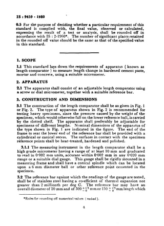
j Page 4, clause 3.1, J;fth sentem ) - Substitute the following for the
existing matter:
‘ The end of the yoke opposite to the micrometer end of the reference bar
shall be provided with an anvil having a cylindrical or conical recess.’
( Page 4, clause 3.1.1, line 5 ) - Substitute cyoke ‘for ‘ frame ‘.
( Page 4, clause 3.2, line 4 ) - Substitute ‘ 12 mm ‘for ‘ 20 mm ‘.
( Page 5, Fig. 1 ) - Substitute ‘ YOKE ‘for ‘ PILLAR ‘.
( Page 6, Fig. 2 ) - Substitute the figure given on page 2 for the
existing figure.
[ Page 7, Tuble 1, co13, Sl Jvo. (i) ] -Substitute ‘ ISLC 150 or ISMC 150
conforming to IS : 226.1975+’ for the existing matter.
13. AMENDMENT NO. 2 APRIL 1993
TO
IS 9459: 1980 SPECIFICATION FOR APPARATUS FOR
USE IN MEASUREMENT OF LENGTH CHANGE OF
HARDENED CEMENT PASTE, MORTAR AND
CONCRETE
( Puge 6, clause 33) -Substitute the following for the existing clause:
‘3.3 Except where the tolerances ate specifically indicated against the specified
dimensions, all dimensions shall be taken as nominal dimensions with tolerances
as laid down in IS 2102 ( Part 1) : 1980*.’
( Page 6,jbor-nofe) - Insert the following foot-note at the cud:
“General tolerances for dimensions and form and position: Part 1 General tolrranc~s for linear and
angular dimensions ( rccrmd revision ).“
(Page 7, Table 1) :
i) Substitute ‘Yoke’/or ‘Pillars’ in co12 of Sl No. (ii).
ii) Delete ‘conforming to relevant Indian Standards’ from the NOTE.
(CED2)
Prmted atNew India Prmttng Press, Khqa, India