Download to read offline

![Prof. Dr. Ammar Yaser Ali and Ahmed Mohammed Mahdi
http://www.iaeme.com/IJCIET/index.asp 26 editor@iaeme.com
Cite this Article: Prof. Dr. Ammar Yaser Ali and Ahmed Mohammed Mahdi.
Analysis for Behavior And ultimate Strength of Concrete Corbels with Hybrid
Reinforcement. International Journal of Civil Engineering and Technology,
6(10), 2015, pp. 25-35.
http://www.iaeme.com/IJCIET/issues.asp?JType=IJCIET&VType=6&IType=10
1. INTRODUCTION
Corbels are short cantilevers with a shear span to depth ratio lower than unity which
tend to act as deep beams or simple trusses rather than flexural members [1], they are
generally built monolithically with the columns or walls. They are also used
particularly in precast structures where their principal function is the transfer of
vertical and horizontal forces to supporting principal members.
Corbels are principally designed to resist the ultimate shear force Vu applied to
them by the beam and they behave like short cantilevered deep beam so the common
behavior is governed by shear rather than flexural. The applied loads are transferred
predominately through shear, because of the usually low shear span to effective depth
ratio. The mechanical behavior of concrete corbels at failure may be either a flexural
failure or beam-shear failure after yielding of the reinforcement. The ultimate strength
of a corbel can be calculated by taking it to be lesser of (a) shear strength of the corbel
interface, which can be calculated using the shear friction theorem; and (b) vertical
load that cause to the development of the flexural ultimate strength of the corbel-
column interface [2].
FRP internal reinforcement is widely used in commercial applications as an
alternative to conventional steel reinforcement primarily to enhance the corrosion
resistance of reinforced concrete structures. Three important physical characteristics
of fiber reinforced polymer materials must be considered: high-tensile strength; low-
modulus of elasticity; and linear-elastic brittle behavior to failure [3]. CFRP bars
using in the present study with steel bars as hybrid reinforcement in primary or
secondary reinforcement.
2. EXPERIMENTAL PROGRAM
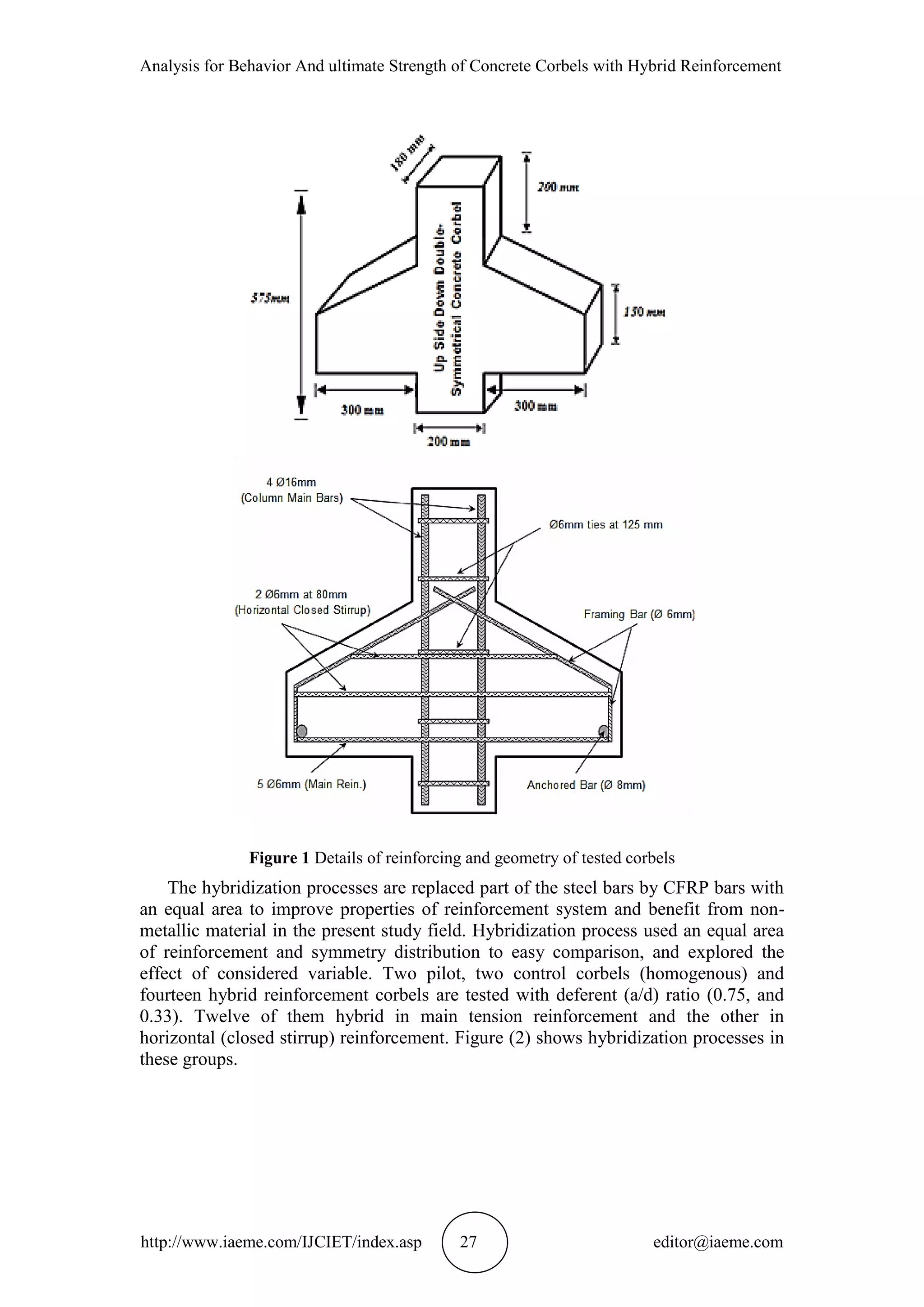
A total of eighteen corbels were tested under vertical distributed applied load. The
experimental study consisted of two test groups. Group (A) included main hybrid
reinforcement with percentage (20%, 40%, 60%, 80%, and 100%), while Group (B)
included horizontal (closed stirrup) hybrid reinforcement with percentage (50%, and
100%). The two (a/d) ratios evaluated were (0.75), and (0.33) used in each one of the
test groups (A and B).
As shown in Figure (1), the column supporting the two corbels cantilevering on
opposite side was 200mm by 180mm in cross section and 575mm long. Corbels had
cantilever projection length of 300mm, 180mm width, and total depth of 275mm at
face of column and 150mm at the free end, and the effective depth 240mm with shear
span 180 mm, or 80 mm. Columns were reinforced with four deformed bars having a
16mm diameter and stirrups having a 6mm diameter placed at pitch of 125mm. The
primary reinforcement (main bars) having diameter 6mm of steel and/or CFRP bars
with varying ratios of hybridization, placed at the top of the corbel with an effective
cover of 35mm. Main bars were welded with cross bar of 8mm diameter , near the end
of each corbels, to provide additional anchorage. The horizontal closed stirrup having
diameter 6mm of steel and/or CFRP bars with varying ratios of hybridization. These
closed stirrups were anchored by framing bars of diameter 6mm.](https://image.slidesharecdn.com/ijciet0610003-151104125043-lva1-app6892/75/Ijciet-06-10_003-2-2048.jpg)
![Analysis for Behavior And ultimate Strength of Concrete Corbels with Hybrid Reinforcement
http://www.iaeme.com/IJCIET/index.asp 29 editor@iaeme.com
searched for a way that led us to do that, galvanized steel clamp was the acceptable
way for this purpose. Ordinary portland cement (Type I) from Iraq plant named
TASLUJA. Crushed gravel from Al-Nibaey region with maximum size of (14 mm).
Natural sand from AL-NAJAF city in Iraq with maximum size of (4.75 mm) and
fineness modulus of (2.46) [4].
Normal strength concrete was used to cast all specimens. Normal strength
concrete mix was designed in accordance with ACI-211 mix design with nominal
compressive strength of about (30MPa). In order to select the mix proportion for the
concrete used in preparing the reinforced concrete corbels, three trial mixes were
carried out in order to obtain cylinder strength of (30MPa) after age 28-days.The final
mix used was 1:1.8:2.3 by weight. The water cement ratio was equal to 0.53 and
cement content was 407 kg/m3.
4. TEST MEASUREMENT AND INSTRUMENTATION
The hydraulic universal testing machine has a capacity of (2000 kN) was used to test
the corbel specimen, as shown in Plate (1). The deflections were measured by means
of (0.01 mm) accuracy dial gauge. Strain of concrete measured used demic point and
dial gauge with accuracy of (0.001 mm).
5. TEST PROCEDURE
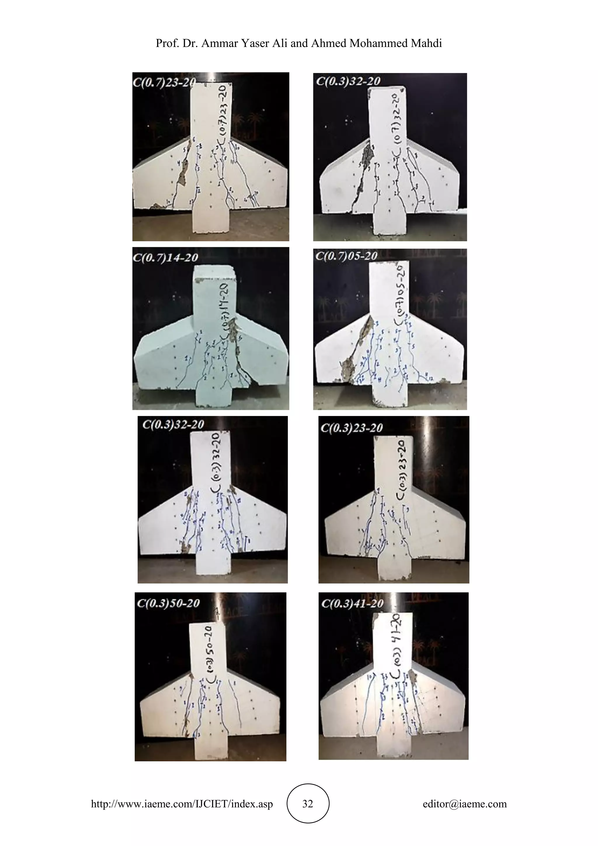
All corbels were painted with white color to observe the crack development and
marked, demic discs were fixed on marking location. At first, the specimens loaded
by 5 kN to seat the support and the loading system, then unloading to zero. The load
increment was 15 kN along the test. The deflection corresponding to the applied load
was measured at every load step at center of column. Also, recording the first crack
load, the ultimate load, and the concrete strain were measured, for each corbel. Finally
the maximum crack width was measured at the end the test by crack meter.
Plate 1 Testing Machine](https://image.slidesharecdn.com/ijciet0610003-151104125043-lva1-app6892/75/Ijciet-06-10_003-5-2048.jpg)


![Analysis for Behavior And ultimate Strength of Concrete Corbels with Hybrid Reinforcement
http://www.iaeme.com/IJCIET/index.asp 35 editor@iaeme.com
hybridization in main reinforcement only with (a/d) (0.75, and 0.33) respectively and
decreased by about (18.6%) and (13.9%) for specimens hybridization in closed stirrup
only with (a/d) (0.75) and a little effect in first crack load with (a/d) (0.33) when
increased the hybridization ratio (50% to 100%).
For concrete corbels with hybrid reinforcement in main tension and with (a/d)
(0.75), the mode of failure altered from tension to compression flexural failure
followed by diagonal splitting with increasing the hybridization ratio. While the
corbels with (a/d) (0.33), the mode of failure classified as shear-friction failure
without changing.
For concrete corbels with hybrid reinforcement in horizontal closed stirrup and
with (a/d) (0.75), the mode of failure altered from flexural tension failure to premature
diagonal splitting failure with increasing the hybridization ratio. While the corbels
with (a/d) (0.33), the mode of failure classified as shear-friction failure without
changing.
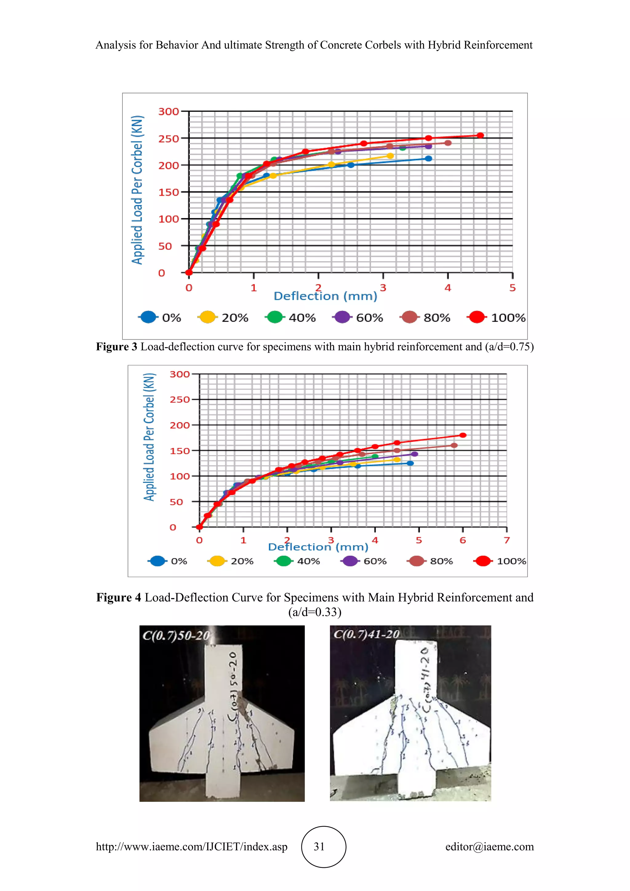
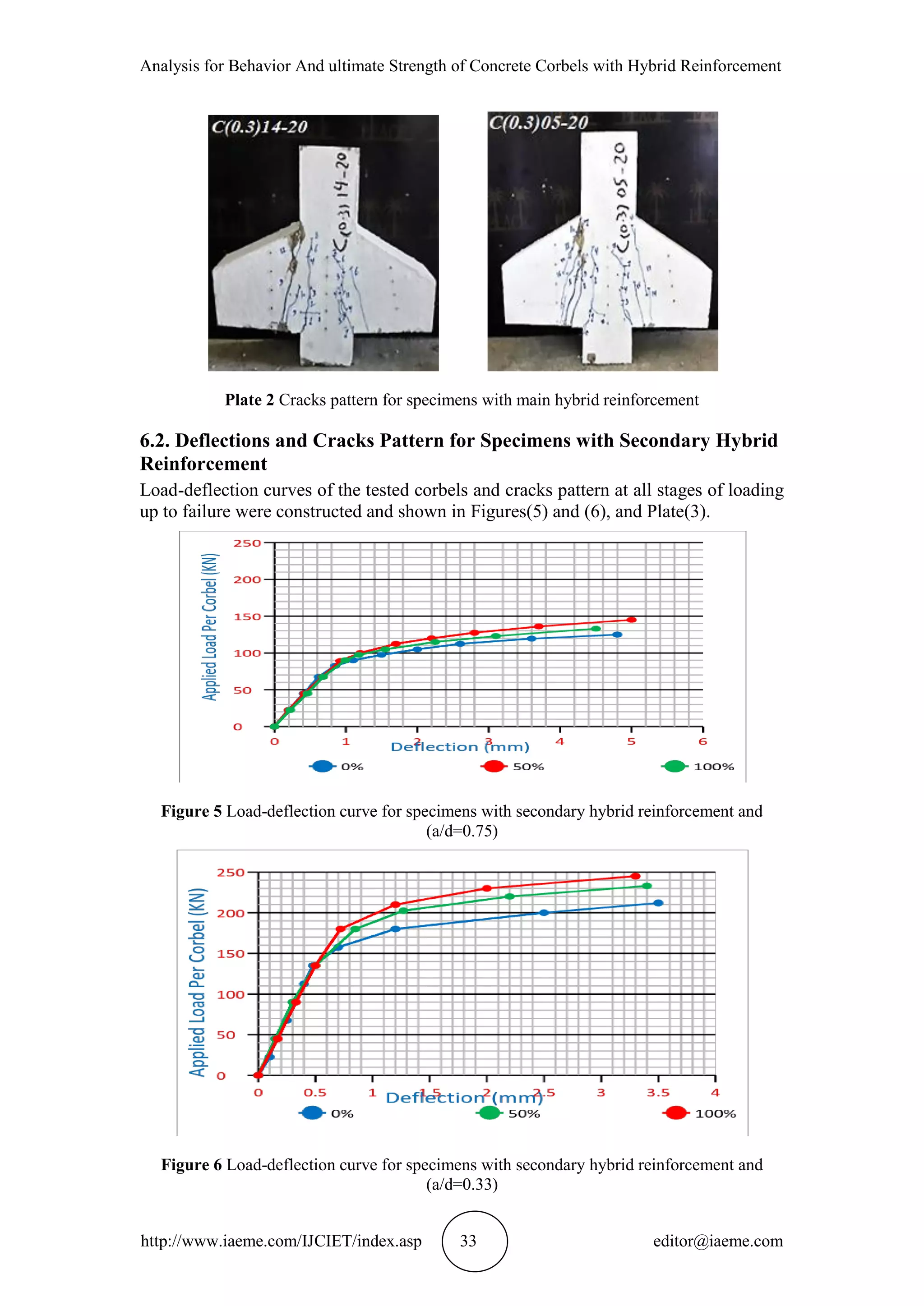
Deflection at service loads increase for all specimens with increase the
hybridization ratio, due to brittle behavior, lower modules of elasticity, and lower
bond strength for CFRP bars, in sup-group AI (main hybrid reinforcement with (a/d)
(0.75)) the deflection increasing (18.75% - 125%) and for sup-group AII (main hybrid
reinforcement with (a/d) 0.33)) the increasing (18.4% - 67.3%), for sup-group BI, and
BII (secondary hybrid reinforcement with (a/d)(0.75, and 0.33) the increasing (20% -
22.5%), (12.2% - 22.4%), respectively with increase the hybridization ratio (50% to
100%).
The ultimate shear strength predicted by the numerical analysis were close to that
measured during experimental testing with maximum difference (2.8%) as average.
The first cracking load obtained from numerical data showed results lower than
the experimental data recorded with difference about (8.75%) as average.
8. REFERENCES
[1] ACI Committee 318, 2011, Building Code Requirements for Structural Concrete
(ACI 318-11), American Concrete Institute, Farmington Hills, USA, pp. 190-
194.
[2] Mattock, A. H., Chen, K.C, and Soongswang, K., 1976, The Behavior of
Reinforced Concrete Corbels, Journal of PCI Journal, March, pp. 53-77.
[3] ACI Committee 440, 2006, Guide for the Design and Construction of Concrete
Reinforced with FRP Bars (ACI 440.XR), American Concrete Institute,
Farmington Hills, pp. 100-106.
[4] Javaid Ahmad and Dr. Javed Ahmad Bhat. Ductility of Timber Beams
Strengthened Using CFRP Plates. International Journal of Civil Engineering and
Technology, 4(5), 2013, pp. 42 – 54.
[5] Iraqi Specification No.45, 1984, Natural Sources for Gravel that is used in
concrete and construction, Baghdad, 1984.
[6] Iraqi Specification No.5, 1984, Portland cement, Baghdad, 1984.
[7] Yaman S.S. Al-Kamaki, Riadh Al-Mahaidi and Azad A. Mohammed. Behavior
of Concrete Damaged By High Temperature Exposure and Confined with CFRP
Fabrics. International Journal of Civil Engineering and Technology, 5(8), 2014,
pp. 148 - 162.](https://image.slidesharecdn.com/ijciet0610003-151104125043-lva1-app6892/75/Ijciet-06-10_003-11-2048.jpg)

The document analyzes the behavior and ultimate strength of concrete corbels with hybrid steel and CFRP reinforcement. Eighteen corbel specimens were tested under vertical loads. The experimental program investigated the effects of hybrid reinforcement ratio, location of hybrid bars, and shear span-to-depth ratio. Results showed that hybrid reinforcement led to increased load capacity and stiffness, but reduced ductility compared to steel-only reinforcement. Increasing the CFRP ratio in main or secondary reinforcement resulted in 5.6-44% and 2.3-20% higher ultimate loads, respectively. Failure modes also changed with higher CFRP ratios.