Downloaded 26 times

![IS 9429 : 1999
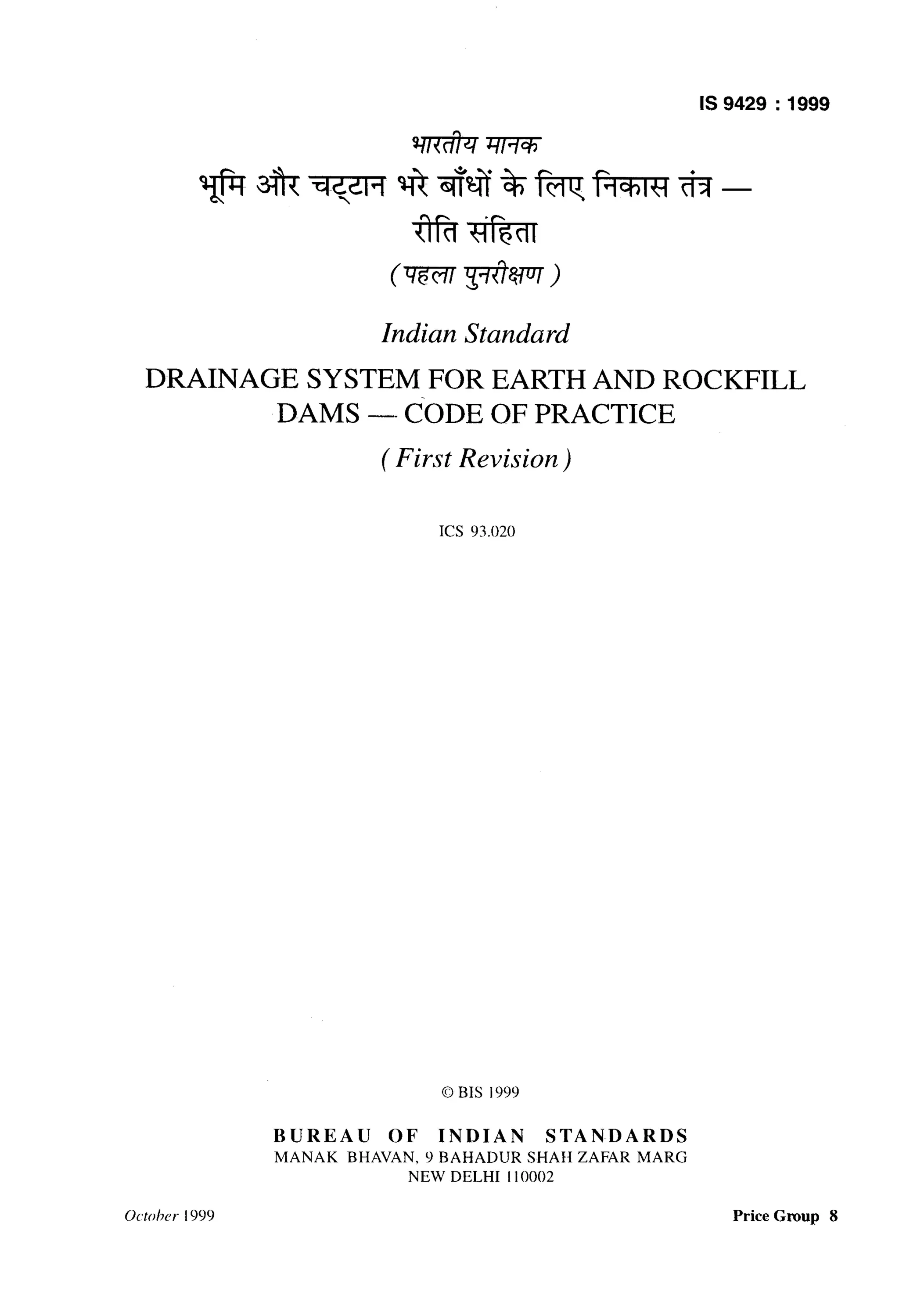
7.1.1.2 To satisfy the permeability requirement of filter
material, minimum D,, (F) shall be greater than or equal
to 5 x D,,(B) but not less than 0.Imm
D,,(F)>5 D,,(B)>O.l mm
7.1.1.3 Maximum D,, Q shall be determined from
Table 2. It should not be smaller than 0.2 mm (See also
Notes I to4).
Table 2 Criteria for Filters
SI Base Soil Base Soil Description Filter
No. Category and Percent Finer Criteria
than 75 Microns
(1) (2) (3) (4)
i) 1 Fine silts and clays, more D,,(F) I9D,,@)
than 85 percent finer 20.2mm
ii) 2 Sands, silts, clays and silty D,,(F) (0.7mm
and clayey sands;40 per-
cent to 85 percent finer
iii) 3 Silty and clayey
sandsand gravels
40-A
D,,(F) 5 L__ x
40- 15
iv) 4
15 percent to 39 per-
cent finer
Sands and gravels;
less than 15 percent
tiner
[4 D,,(B) - 0.7mm
+ 0.7mm]
D,,(F) L 4 D,,(B)
NOTES
1 Filters should have a maximum particle size of
75 mm. Material passing the 75 micron sieve shall not
exceed 5 percent and should be non-cohesive.
2 When 9D,,(E) is less than 0.2 mm, 0.2 mm should be used.
3 ‘A’ is the percent passing the 75 micron sieve after any
regrading.
4 When 4D,, (B) is lessthan 0.7 mm,0.7 mm shouldbe used
(applicable for base soil category 3).
7.1.1.4 To minimize segregation, filters should have
relatively uniform gradation. Filters with D,,(F) less
than about 20 mm, do not generally segregate. How-
ever for preventing segregation during construction
of filter in other cases, limits of D,,(F) and D,,(F) are
givenin Table 3.
Table 3 LimitsofD,,Q and D,(F) for Preventing
Segregation
SI
No.
(1)
i)
ii)
iii)
iv)
v)
vi)
D,,(F) J&“(F)
Min Max
(mm) (mm)
(2) (3)
< 0.5 20
0.5-1.0 25
1.0-2.0 30
2.0-5.0 40
5.0-10 50
10-50 60
7.1.2 In the above clauses the sufftx ‘F denotes filter
material and ‘B’basematerial. The subscripts 10,15,85
or 90, refer to the percentage finer by weight. For coarse
filters the base material should be taken as fine filter,
fqr the purpose of gradation.
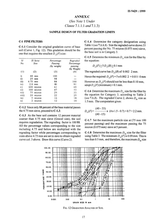
7.1.3 An example of determining filter gradation limits
is given in Annex C.
10](https://image.slidesharecdn.com/9429-130717121451-phpapp02/85/9429-12-320.jpg)
![IS 9429 : 1999
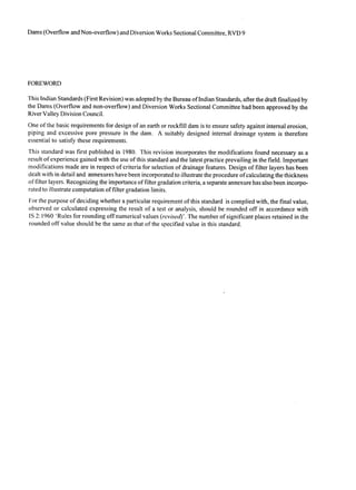
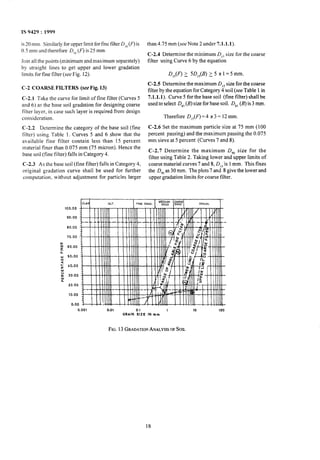
INCLINEDFILTER
HORIZONTALFILTER(FINE)
1
9A
I_, _ 2oo m ’ ~IF~I SURFACE_]
9B
HORIZONTAL FlLTcl7 (FINE)
K = 1.67 x 10-h/s 7
L STRIPPED SURFACE
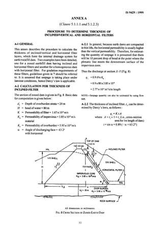
FE. 9 INCLINEDANDHORIZONTALFILTERSECTION
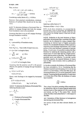
A-3.1 The quantity of seepage through body of the H
dam is given by: = 0.2 K,x - x dr
Quantity = y, x K,
L*
50
YO = m-d = 0.2x5.95x 1O-8x--- x20
= w-56
143.5
=
= 19m
0.082 x 10” m3Mm length
Hence quantity = 19x3.85x10-* A-3.3 Thickness of horizontal filter.
of seepage
= 0.73x 10” m3/s/m
Total discharge = (0.73 + 0.082) x 10” m3/s
A-3.2 Assuming 80 percent efficiency of foundation
= 0.812 x 1O-6m3/s.
treatment the quantity of seepage through foundation The thickness of horizontal filter can be calculated by:
will be :
K. t;
Quantity = 0.2 Kri. A 4 =-
4](https://image.slidesharecdn.com/9429-130717121451-phpapp02/85/9429-15-320.jpg)

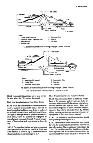
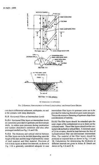
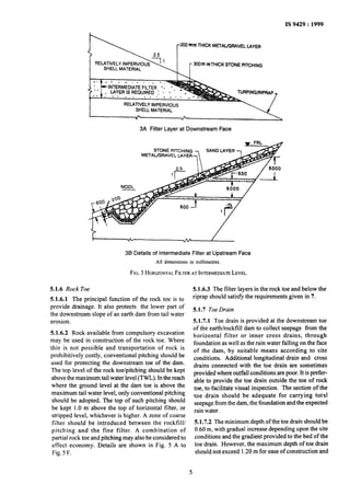
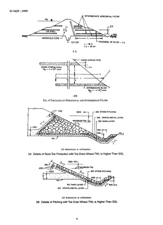
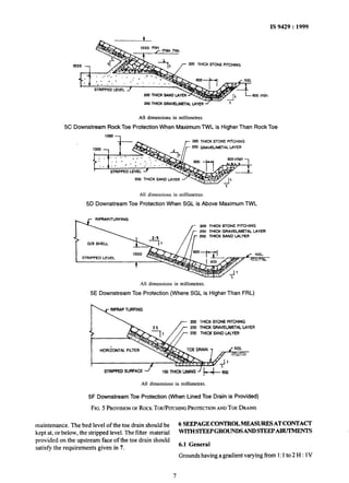
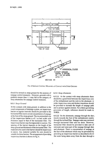
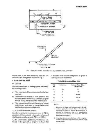
This document provides guidelines for designing drainage systems for earth and rockfill dams. It discusses key considerations like controlling pore pressures, internal erosion, and piping. The guidelines cover selecting appropriate drainage features based on the dam type and materials. Features discussed include inclined/vertical filters, horizontal filters, longitudinal and cross drains, transition zones, rock toes, and toe drains. Filter material criteria and design procedures are also outlined.


