Download to read offline
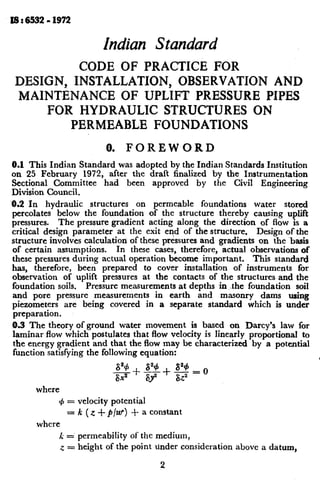
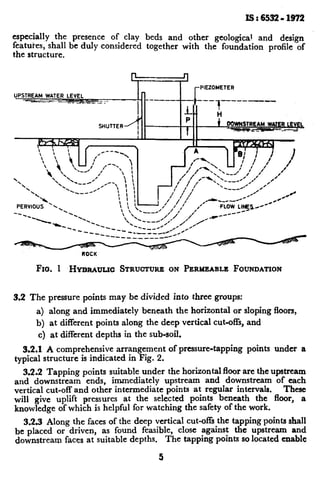
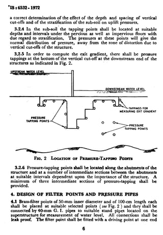
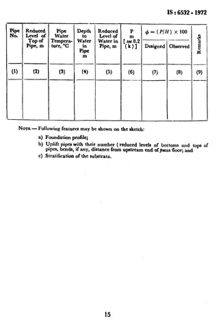

This document provides guidelines for designing, installing, observing, and maintaining uplift pressure pipes for hydraulic structures built on permeable foundations. It discusses how water seepage below these structures can cause uplift pressures that impact stability if not properly accounted for. The standard provides recommendations on locating pressure tapping points along horizontal floors, vertical cut-offs, and at various subsoil depths to monitor pressures and ensure design assumptions remain valid. Regular observation of pressure readings is important for both assessing safety and maintenance of these types of hydraulic structures.


