This document outlines Indian Standard IS:9013-1978 which establishes a method for making, curing, and testing concrete specimens using accelerated curing techniques. It describes two accelerated curing methods - the warm water method and boiling water method. The standard provides requirements for molds, curing tanks, specimen preparation, curing procedures, and compression testing to allow for early assessment of concrete strength for construction quality control purposes. It seeks to enable evaluation of concrete strength within 24 hours of casting instead of the traditional 28-day testing period.
The document provides an overview of asphalt surfacing types and their application, covering basic asphalt principles like mix design and production, the uses and types of asphalt including dense graded asphalt and stone mastic asphalt, and guidance on treatment selection for different traffic and road conditions. The goal is to help participants develop an understanding of asphalt design, practice, and selection of the appropriate surfacing type.
A diaphragm wall is a reinforced concrete wall constructed underground using a slurry trench technique. A slurry trench involves excavating in a trench filled with a thick, viscous fluid called slurry that balances pressure to prevent trench collapse. Reinforcing cages are lowered into the trench and concrete is poured by tremie to displace the slurry. Diaphragm walls can be built close to existing structures, to great depths, and provide strong, watertight basement walls. However, they require specialized equipment and have high costs.
Coffer dams are temporary structures built to retain water and soil in order to create a dry work area for construction projects. There are several types of coffer dams suited to different conditions, including earth-filled, sheet pile, and cellular designs. Key considerations in selecting a coffer dam include water depth, area size, soil/river bed conditions, and potential for erosion or flooding. Proper design is needed to withstand hydrostatic pressures and ensure structural integrity until the permanent structure is complete.
Pile foundation are essential in case where SBC is low or the load coming from superstructure is too heavy,
Topics covered includes Materials used for making piles, Type of piles, load transfer mechanism, factors affecting selection of piles, Installation methods, load carrying capacity of piles, different load tests performed and the behavior of piles as a group.
This document discusses underwater concrete, including its production, placement methods, and quality control. It notes that underwater concrete must have proper mix design and flowability to consolidate under its own weight without vibration. The main placement methods described are tremie, pump, toggle bags, and bagwork. Quality control includes monitoring placement rate and volume. Common issues with underwater concrete include cement washout, laitance, and segregation, which mix design and proper placement seek to prevent.
This document summarizes a presentation on subgrade stabilization methods for concrete pavements. It discusses the role of the subgrade in pavement performance and outlines various treatment options including removal and replacement, compaction, geotextiles, chemical stabilization using lime and cement. The presentation provides details on laboratory testing and construction steps for lime and cement stabilization, including mixing, compaction, curing and quality control. Subgrade stabilization improves the strength and uniformity of the subgrade for use as a construction platform and structural layer.
This document discusses bubble deck slabs, which are biaxial voided concrete slabs that use hollow plastic spheres to replace inactive concrete in the center. Bubble deck slabs provide structural advantages like less weight, increased strength, and the ability to span longer distances without needing beams. Experimental studies show bubble deck slabs have similar shear strength and deflections to solid slabs but are 40% lighter. They provide construction, engineering, environmental, and economic benefits. The first high-rise building constructed with bubble deck slabs was the 131m tall Millennium Tower in Rotterdam. Bubble deck slabs may become more widely used for constructing skyscrapers and other structures in the future.
Design principles in prefabricated structures unit iii ce6016 pfsPrakash Kumar Sekar
CE6016 PREFABRICATED STRUCTURES - Design principles in prefabricated structures unit iii ce6016 pfs - Disuniting of structures- Design of cross section based on the efficiency of material used – Problems in design because of joint flexibility ---- Allowance for joint deformation
This document discusses Direct Mud Circulation (DMC) piling, which is a replacement piling method. It provides an overview of the DMC piling process, including the equipment used such as the DMC rig, chisel, and tremie pipes. The key steps of the DMC piling method are described, including boring the hole with a chisel using water jets, adding reinforcement cages, and filling the holes with concrete poured from the bottom up using tremie pipes. The document concludes that DMC piling is a common and economic piling technique for piles from 450mm to 1000mm in diameter and 25m to 30m in depth.
This document summarizes a project report on high strength (M70) and high performance concrete. It lists the project team members and their institution. It then provides details on the properties, methods to achieve, parameters, and material selection for high performance concrete. The document discusses the work done on mix design, laboratory tests, mix preparation, test results and conclusions for M70 concrete.
This document provides information about pavement testing equipment from PaveTesting Ltd., including falling weight deflectometers (FWDs). It summarizes that PaveTesting offers a range of FWDs from trailer-mounted and vehicle-mounted options for standard pavements to heavier models for runways and parking lots. FWDs measure pavement deflection to determine properties like thickness, stiffness, and expected life. PaveTesting also provides training and support services.
This document discusses pile foundations and provides a literature review on the topic. It was prepared by three students and covers the objectives, introduction, loads on pile foundations, pile materials, and concludes with recommendations on selecting pile materials based on site conditions. The literature review section lists 5 sources published between 1980-2014 on topics related to pile foundation behavior, analysis, and design under bridges.
Pile foundation ppt 2 (usefulsearch.org) (useful search)Make Mannan
Pile foundations are used when the bearing capacity of soil is low or uneven and the soil is located at a greater depth. Piles transfer structural loads directly to the soil layer below by end bearing or side friction. Common pile types include timber, concrete, steel, and composite piles which are classified based on function, material, and installation method. Pile foundations provide solutions for difficult soil conditions like compressible, waterlogged, or made ground and are widely used for bridges, buildings, and marine structures.
Initial and routine load tests are conducted on piles to confirm design load calculations. Initial tests apply 2.5 times the safe carrying capacity to piles and routine tests apply 1.5 times. Initial tests establish acceptance limits for routine tests. Routine tests are conducted on 1/2-2% of piles to ensure safe load capacity and detect unusual performance. Vertical, lateral, and pull-out load tests are conducted according to IS standards and involve measuring pile settlement under increasing loads held for durations. Acceptance criteria consider settlement and load levels.
1) Eccentric connections experience both direct axial forces and bending moments due to eccentric loads. This results in more complex stress distributions compared to concentric connections.
2) For bracket connections with eccentric loads, the direct shear stress and bending stress due to the moment must be calculated and combined using the Pythagorean theorem.
3) For welded joints with eccentric loads, both the direct shear stress and bending stress in the weld must be determined and combined, considering the weld geometry, load magnitude and eccentricity. The resultant stress must satisfy allowable stress criteria.
Prestressing Concept, Materials and Prestressing System - Section B, Group 1সাফকাত অরিন
This document provides an overview of prestressing concepts, materials, and systems. It discusses the basic concepts of prestressing including transforming concrete into an elastic material, combining high-strength steel with concrete, and achieving load balancing. The document describes the advantages and limitations of prestressing. It also summarizes the different types of prestressing in terms of the source of prestressing force, whether it is external or internal, pre-tensioned or post-tensioned, linear or circular, full or partial, and uniaxial, biaxial, or multiaxial. Finally, it discusses prestressing materials including concrete, aggregate, cement, water, admixtures, grout, and prestressing steel.
Overview of Soil Stabilization :Cement / Lime :PPTAniket Pateriya
Soil-cement is frequently used as a construction material for pipe bedding, slope protection, and road construction as a sub-base layer reinforcing and protecting the subgrade. It has good compressive and shear strength, but is brittle and has low tensile strength, so it is prone to forming cracks.
Lime can be used to treat soils to varying degrees, depending upon the objective. The least amount of treatment is used to dry and temporarily modify soils. Such treatment produces a working platform for construction or temporary roads. A greater degree of treatment supported by testing, design, and proper construction techniques--produces permanent structural stabilization of soils.
Study on the effect of viscous dampers for RCC frame StructurePuneet Sajjan
1. The study analyzed the effect of adding viscous dampers to an 8-story reinforced concrete building modelled in ETABs software.
2. Dynamic analysis using response spectrum method showed that adding viscous dampers reduced displacement by up to 64%, story drift by up to 70%, and story shear by up to 30% compared to the model without dampers.
3. Viscous dampers work by dissipating energy through the flow of silicone-based fluid between piston-cylinder arrangements when the structure vibrates, reducing seismic loads on the building.
Quality tests for aggregates and concrete mix designAyaz khan
This document provides information and procedures for testing the quality of aggregates used in concrete. It discusses testing the gradation of coarse and fine aggregates, determining specific gravity, and checking for clay lumps, flat and elongated particles, abrasion resistance, organic impurities, soundness, and stripping. Procedures are outlined for sieve analysis, specific gravity, clay lump, and flaky particle tests. The document also mentions mix design testing for concrete.
Self-compacting concrete (SCC) was developed in Japan in the 1980s to solve issues with inadequate concrete compaction. SCC is highly flowable under its own weight and fills formwork without vibration. It was pioneered by Professor Hajime Okamura and has seen increasing use globally since 2000. The document discusses the constituents, properties, testing, and advantages of SCC compared to traditional vibrated concrete.
Pervious concrete allows water to pass directly through, reducing runoff and allowing groundwater recharge. It consists of cement, coarse aggregate, and 15-35% voids. It has strengths of 3.5-28 MPa and permeability of 120 L/m2/min. Applications include low-traffic pavements, parking areas, and sidewalks. Advantages are reduced runoff, groundwater recharge, and no need for retention ponds. Maintenance is required and it has lower strength than conventional concrete.
This document provides specifications for different classes of buildings and roads. It defines specifications as describing the nature, materials, and workmanship for a construction project. Building specifications are classified as general or brief (covering foundation, walls, roofing, etc. for different classes) and detailed. It provides the general specifications for various components like foundation, walls, roofing, flooring and finishing for first, second, third and fourth class buildings. Road specifications include details for subgrade, soiling, intercoat, topcoat, brick edging and considerations for heavy traffic or weak subgrade.
The document discusses different types of foundations for structures, including shallow and deep foundations. It describes spread footings, mat/raft foundations, piles, piers, and caissons. Spread footings are the most common shallow foundation and involve concrete slabs under columns and load-bearing walls. Mat/raft foundations use a continuous slab to spread loads over a large area, especially for high loads or poor soil. Deep foundations like piles, piers, and caissons extend deeper into the ground to bear loads in stronger soil layers. Piles transfer loads through end bearing or friction, while piers and caissons are constructed by excavating holes and filling with concrete.
Placing and compaction of cement concretePramod GK
This document discusses placing and compaction of concrete. Placing involves depositing fresh concrete in its final position without dropping from height or piling to avoid segregation. Foundations require trenches be excavated and beds prepared before concrete is placed using chutes or tremie pipes for deep placements. Compaction removes air bubbles and improves packing using hand tools, internal vibrators like poker vibrators inserted in concrete, or external vibrators applying surface vibration. Proper placing and compaction results in dense, strong concrete.
This document provides an overview of concrete pavement construction for roads. It discusses the importance of road networks for development and describes the different types of roads in India. It then defines road pavement and describes the main types - flexible and rigid. Flexible pavement uses bitumen and has low initial cost but higher maintenance, while rigid pavement uses concrete and has higher initial cost but lower long-term maintenance. The document outlines the basic components of concrete pavement including cement, aggregates, water, and equipment used. It then explains the various steps of the construction process from site preparation to forming, placing concrete, compaction, curing and finishing.
Bearings are interfaces between bridge superstructures and substructures that allow for movement caused by thermal expansion, live loads, wind loads, and other factors. The main types of bearings are sliding, roller, elastomeric, and pot bearings. Sliding bearings use steel plates and require regular greasing. Roller bearings use steel rollers and can accommodate more movement than sliding bearings. Elastomeric bearings are made of rubber and allow for movement in all directions with little maintenance. Pot bearings encase an elastomeric pad in a metal pot and can accommodate unlimited movement while preventing compression of the elastomer. Proper selection, inspection, and maintenance of bearings is important for the long
Principles and design concepts of reinforced soil wallsPrakash Ravindran
Reinforced soil walls are cost-effective retaining structures that can tolerate large settlements. They consist of layers of soil reinforced with tensile inclusions like geogrids or geotextiles. The reinforcement improves the soil strength allowing near-vertical faces to be constructed. Key advantages include flexibility, rapid construction, and ability to absorb movements. The document discusses design principles like external stability checks against sliding and bearing capacity failure. Internal stability checks reinforcement rupture and pullout capacity. Settlements, seismic design, and typical failures are also covered.
This document provides the standard method for determining the drying shrinkage of autoclaved cellular concrete products in 3 sentences:
The standard outlines preparing prismatic specimens of autoclaved cellular concrete and fully saturating them in water before taking initial and final length measurements over time as the specimens dry at a controlled temperature and humidity, in order to calculate the drying shrinkage as a percentage change in length. It specifies requirements for the measuring instruments, immersion tank, storage room or humidity chamber, and includes details on specimen dimensions, testing procedures, calculations, and reporting the results.
This document outlines test methods for assessing the particle size and shape of aggregates used in concrete from an Indian Standard published in 1963. It includes procedures for sieve analysis to determine particle size distribution, and tests for materials finer than 75 microns, flakiness index, elongation index, and angularity number. The goal is to assist in evaluating the quality of aggregates used in concrete construction in India by testing relevant properties. Maximum sample weights and sieve sizes are provided for different tests.
This document provides standards for testing the strength of concrete in India. It outlines procedures for making and curing compression test specimens in a laboratory setting, including sampling materials, mixing, compacting, and curing the concrete specimens. It specifies that test specimens should be 150mm cubes or 150mm diameter cylinders for compressive strength testing. The document also references other Indian standards for materials used in concrete like cement, aggregates, and sieves.
This document outlines test methods for determining various properties of aggregates used in concrete from the Indian Standard IS:2386 (Part III) - 1963. It describes 4 methods (I-IV) for determining specific gravity, apparent specific gravity, water absorption and bulk density of aggregates. Method I is for aggregates larger than 10mm, Method II for aggregates between 40mm and 10mm, Method III for aggregates smaller than 10mm. The tests involve weighing samples in and out of water, surface drying, oven drying and calculating properties from weight changes. Reporting of individual and mean test results is recommended.
This document provides specifications for precast concrete kerbs, channels, edgings, quadrants, and gutter aprons. It outlines materials requirements including cement, aggregates, and concrete strength. It describes standard section dimensions and tolerances. Finish and color can be specified by the purchaser, with natural being default. The document aims to incorporate revisions from updated related standards to align with current Indian precast concrete industry practices.
This document provides specifications for broken brick coarse aggregate for use in lime concrete. It outlines:
- The general quality requirements for the broken bricks, including that they must be well-burnt and free of impurities.
- The physical requirements for the aggregate, including specifications for grading, bulk density, impact value, water absorption, and soluble matter content.
- The sampling methods to be used.
It also includes appendices describing the test methods for determining water absorption and soluble matter content of the aggregate.
This document provides a code of practice for the construction of autoclaved cellular concrete block masonry. It outlines materials and design considerations for constructing load-bearing and non-load bearing walls using these blocks. The document discusses block requirements, mortar mixes, wall thickness, bracing, and modular coordination. It aims to help builders properly use this type of masonry and ensure structural safety and avoidance of cracks.
This document provides a 3-sentence summary of the petrographic examination methods for aggregates used in concrete as outlined in the Indian Standard IS: 2386 (Part VIII) - 1963:
The standard describes Method I for routine petrographic examination which involves visually inspecting and segregating coarse and fine aggregate constituents based on petrographic and chemical differences across various sieve sizes. Method II is for detailed investigations and serves as the reference method. Both methods require examination of aggregate fractions by a qualified petrographer to identify coatings, minerals, particle shape and other properties that could impact the quality and durability of concrete.
The document provides specifications for an apparatus used to measure the length change of hardened cement paste, mortar, and concrete. It describes the construction, dimensions, materials, and markings required for a length comparator, which uses a micrometer to measure the change in length of specimens against a reference bar. The length comparator consists of an adjustable frame that holds either a screw or dial micrometer and allows measurement of specimens of different lengths.
This document provides guidelines for sampling and analyzing concrete. It discusses terminology related to concrete testing and outlines methods for sampling fresh concrete in the field. The document contains 3 sections - terminology, sampling fresh concrete, and sampling hardened concrete. It aims to standardize concrete testing methods to help ensure quality control and the performance of concrete structures.
This document provides design tables for concrete structures used to store liquids. It includes tables for moment coefficients, shear coefficients, and other structural design values for rectangular and cylindrical concrete tanks. The tables are intended to aid engineers in quickly designing these types of structures. Rectangular tank tables cover individual wall panels and continuous walls, while cylindrical tank tables are also provided. Considerations for underground tanks subjected to earth pressures are discussed.
This document provides testing methods to determine the mechanical properties of aggregates for concrete. It describes the procedure to conduct an aggregate crushing value test, which involves placing a sample of coarse aggregate in a cylinder apparatus and compressing it at a uniform rate to measure its resistance to crushing. The sample is sieved after the test to determine the percentage of fines produced. It also outlines tests for 10% fines value, impact value, abrasion value, polished stone value, and crushing strength. The aim is to assess the quality and durability of aggregates used in concrete.
This document provides specifications for autoclaved cellular (aerated) concrete blocks as part 3 of the Indian Standard for concrete masonry units. It outlines the classification of blocks into two grades based on compressive strength and corresponding density and thermal conductivity. Dimensional tolerances for the blocks are defined, with the maximum variation in length being 5mm and 3mm for height and width. The document also lists acceptable cement standards and provides context for the use of autoclaved cellular concrete blocks in construction.
The document provides details on test methods for determining deleterious materials and organic impurities in aggregates for concrete according to Indian Standard IS: 2386 (Part II) - 1963. It describes test methods for determining the percentage of clay lumps, clay/fine silt/fine dust content using a sedimentation method, light-weight pieces like coal/lignite, soft particles, and organic impurities in aggregates. The tests aim to assess aggregate quality by identifying deleterious materials. The standard specifies procedures, apparatus, sample preparation and size, calculations, and reporting of results for each test.
This document is the Indian Standard specification for coarse and fine aggregates from natural sources for use in concrete. It outlines various requirements for aggregates including limits on deleterious materials, aggregate crushing value, impact value, abrasion value, and soundness. It defines terms related to aggregates and specifies four grading zones for fine aggregates of different particle sizes. The standard is intended to ensure aggregates are suitable for producing durable concrete structures.
This document is the Indian Standard specification for coarse and fine aggregates from natural sources for use in concrete. It outlines the requirements and limits for quality parameters like deleterious materials, aggregate crushing value, impact value, abrasion value and soundness. It defines terms related to aggregates and specifies four grading zones for fine aggregates of progressively finer sizes. The standard is intended to cover aggregates commonly available in India for general structural and mass concrete construction.
This document describes test methods for determining the soundness of aggregates used in concrete. Specifically, it outlines procedures to test resistance to disintegration when aggregates are immersed in saturated solutions of sodium sulfate or magnesium sulfate. The test involves immersing aggregate samples in the solutions and observing for changes after a specified time period. This provides information about how aggregates may hold up against weathering effects from sulfate salts. The document specifies equipment, reagents, sample sizes and procedures needed to properly conduct the soundness test for both fine and coarse aggregates.
This document provides a code of practice for laying concrete pipes. It includes methods for calculating loads on pipes according to installation conditions and provides corresponding load factors. The purpose is to relate the loads on concrete pipes installed under various conditions to the test strength of the pipe, through appropriate load factors. The document defines key terms, outlines symbols used in calculations, and describes methods to calculate vertical loads on pipes from earth fill material, concentrated loads, and distributed loads. It is intended to be used with other standards for concrete pipes to help ensure pipes are not subjected to loads exceeding their design strength.
This document outlines testing procedures for evaluating the strength, deformation, and cracking of autoclaved cellular concrete flexural members under short duration bending loads. Key points:
- Test specimens should be full-size structural members to be used in construction.
- Members are simply supported and loaded at third points using steel plates to distribute the load evenly.
- Loads, deflections at mid-span, strains, and crack widths are measured.
- Members are loaded until cracking occurs or a prescribed load is reached to evaluate strength, deformation, and cracking behavior under short term bending loads.
This document provides the standard test method for evaluating the performance of screed board concrete vibrators by measuring their ability to compact concrete. The test involves vibrating a 180mm thick concrete slab with a vibrator and taking density measurements from cores cut from the slab. If the density from each core is at least 93% of the maximum theoretical density, the vibrator passes the test. This direct measurement of compaction achieved provides a better assessment of a vibrator's quality than indirect measurements of vibration characteristics alone.
LAND USE LAND COVER AND NDVI OF MIRZAPUR DISTRICT, UPRAHUL
This Dissertation explores the particular circumstances of Mirzapur, a region located in the
core of India. Mirzapur, with its varied terrains and abundant biodiversity, offers an optimal
environment for investigating the changes in vegetation cover dynamics. Our study utilizes
advanced technologies such as GIS (Geographic Information Systems) and Remote sensing to
analyze the transformations that have taken place over the course of a decade.
The complex relationship between human activities and the environment has been the focus
of extensive research and worry. As the global community grapples with swift urbanization,
population expansion, and economic progress, the effects on natural ecosystems are becoming
more evident. A crucial element of this impact is the alteration of vegetation cover, which plays a
significant role in maintaining the ecological equilibrium of our planet.Land serves as the foundation for all human activities and provides the necessary materials for
these activities. As the most crucial natural resource, its utilization by humans results in different
'Land uses,' which are determined by both human activities and the physical characteristics of the
land.
The utilization of land is impacted by human needs and environmental factors. In countries
like India, rapid population growth and the emphasis on extensive resource exploitation can lead
to significant land degradation, adversely affecting the region's land cover.
Therefore, human intervention has significantly influenced land use patterns over many
centuries, evolving its structure over time and space. In the present era, these changes have
accelerated due to factors such as agriculture and urbanization. Information regarding land use and
cover is essential for various planning and management tasks related to the Earth's surface,
providing crucial environmental data for scientific, resource management, policy purposes, and
diverse human activities.
Accurate understanding of land use and cover is imperative for the development planning
of any area. Consequently, a wide range of professionals, including earth system scientists, land
and water managers, and urban planners, are interested in obtaining data on land use and cover
changes, conversion trends, and other related patterns. The spatial dimensions of land use and
cover support policymakers and scientists in making well-informed decisions, as alterations in
these patterns indicate shifts in economic and social conditions. Monitoring such changes with the
help of Advanced technologies like Remote Sensing and Geographic Information Systems is
crucial for coordinated efforts across different administrative levels. Advanced technologies like
Remote Sensing and Geographic Information Systems
9
Changes in vegetation cover refer to variations in the distribution, composition, and overall
structure of plant communities across different temporal and spatial scales. These changes can
occur natural.
Gender and Mental Health - Counselling and Family Therapy Applications and In...PsychoTech Services
A proprietary approach developed by bringing together the best of learning theories from Psychology, design principles from the world of visualization, and pedagogical methods from over a decade of training experience, that enables you to: Learn better, faster!
Leveraging Generative AI to Drive Nonprofit InnovationTechSoup
In this webinar, participants learned how to utilize Generative AI to streamline operations and elevate member engagement. Amazon Web Service experts provided a customer specific use cases and dived into low/no-code tools that are quick and easy to deploy through Amazon Web Service (AWS.)
Strategies for Effective Upskilling is a presentation by Chinwendu Peace in a Your Skill Boost Masterclass organisation by the Excellence Foundation for South Sudan on 08th and 09th June 2024 from 1 PM to 3 PM on each day.
ISO/IEC 27001, ISO/IEC 42001, and GDPR: Best Practices for Implementation and...PECB
Denis is a dynamic and results-driven Chief Information Officer (CIO) with a distinguished career spanning information systems analysis and technical project management. With a proven track record of spearheading the design and delivery of cutting-edge Information Management solutions, he has consistently elevated business operations, streamlined reporting functions, and maximized process efficiency.
Certified as an ISO/IEC 27001: Information Security Management Systems (ISMS) Lead Implementer, Data Protection Officer, and Cyber Risks Analyst, Denis brings a heightened focus on data security, privacy, and cyber resilience to every endeavor.
His expertise extends across a diverse spectrum of reporting, database, and web development applications, underpinned by an exceptional grasp of data storage and virtualization technologies. His proficiency in application testing, database administration, and data cleansing ensures seamless execution of complex projects.
What sets Denis apart is his comprehensive understanding of Business and Systems Analysis technologies, honed through involvement in all phases of the Software Development Lifecycle (SDLC). From meticulous requirements gathering to precise analysis, innovative design, rigorous development, thorough testing, and successful implementation, he has consistently delivered exceptional results.
Throughout his career, he has taken on multifaceted roles, from leading technical project management teams to owning solutions that drive operational excellence. His conscientious and proactive approach is unwavering, whether he is working independently or collaboratively within a team. His ability to connect with colleagues on a personal level underscores his commitment to fostering a harmonious and productive workplace environment.
Date: May 29, 2024
Tags: Information Security, ISO/IEC 27001, ISO/IEC 42001, Artificial Intelligence, GDPR
-------------------------------------------------------------------------------
Find out more about ISO training and certification services
Training: ISO/IEC 27001 Information Security Management System - EN | PECB
ISO/IEC 42001 Artificial Intelligence Management System - EN | PECB
General Data Protection Regulation (GDPR) - Training Courses - EN | PECB
Webinars: https://pecb.com/webinars
Article: https://pecb.com/article
-------------------------------------------------------------------------------
For more information about PECB:
Website: https://pecb.com/
LinkedIn: https://www.linkedin.com/company/pecb/
Facebook: https://www.facebook.com/PECBInternational/
Slideshare: http://www.slideshare.net/PECBCERTIFICATION
Beyond Degrees - Empowering the Workforce in the Context of Skills-First.pptxEduSkills OECD
Iván Bornacelly, Policy Analyst at the OECD Centre for Skills, OECD, presents at the webinar 'Tackling job market gaps with a skills-first approach' on 12 June 2024
How to Make a Field Mandatory in Odoo 17Celine George
In Odoo, making a field required can be done through both Python code and XML views. When you set the required attribute to True in Python code, it makes the field required across all views where it's used. Conversely, when you set the required attribute in XML views, it makes the field required only in the context of that particular view.
हिंदी वर्णमाला पीपीटी, hindi alphabet PPT presentation, hindi varnamala PPT, Hindi Varnamala pdf, हिंदी स्वर, हिंदी व्यंजन, sikhiye hindi varnmala, dr. mulla adam ali, hindi language and literature, hindi alphabet with drawing, hindi alphabet pdf, hindi varnamala for childrens, hindi language, hindi varnamala practice for kids, https://www.drmullaadamali.com
1. IS:9013-1978
(Reaffirmed 1992 )
( Reaffirmed 1999 )
Indian Standard
METHODOFMAKING,CURINGANDDETERMINING COMPRESSIVESTRENGTHOF
ACCELERATED-CUREDCONCRETE
TESTSPECIMENS
( Fourth Reprint DECEMBER
1998 )
( IncorporatingAmendment No. 1)
UDC
666.97.035.5
0 Conright
RUREAU
MANAK
Gr 3
OF
BHAVAN,
INDIAN
: 620.173
1998
STANDARDS
9 BAHADUR
SHAH
NEW DELHI 110002
ZAFAR
MARG
April 1979
2. 1s 89013 1978
-
Indian Standard
METHOD OF MAKING, CURING AND DETERMINING COMPRESSIVE STRENGTH OF
ACCELERATED-CURED
CONCRETE
TEST SPECIMENS
Cement
and Concrete Sectional Committee,
BDC 2
Repwcnting
Chairman
Da H. C. VISVE~VABAYA
Cement Research Institute of India, New Delhi
MSrnbnS
ADDITIONAL DI~ECTOI~, STAXDAEDLI
(B&S)
DEPUTY DIREC~OI~. STanDnRmf
SHRI
SHBI
Research, Designs & Standards Organization
( Ministry of Railways ), Lucknow
( B & S ) ( A~M~G )
K. C. AQQAR~AL
Hindurtan Prefab Ltd, New Delhi
Snur C. L. KA~LIWAL ( Ahrnafc )
B. C. BANRRJEE
Cement Corporation of India Ltd, New Delhi
SHRI A. U. RlJr~srw3IlaNI ( Affcraufe)
SIIBI K. P. BAXEIIJEE
Larsen 8 Toubro Ltd, Bombay
SURI HAIIIEH N. MALANI ( Aifurmfe)
SHItI R. N. BANSAL
Beas Designs Organization, Nangal Township
SHI‘I T. C. CARo ( .i~ferTUlfe )
DR N. S. &AL
Stru;~ct;~e~gineering
Research Centre ( CSIR
CHIEF ENGINEER ( PROJXTS
)
Irrigation
Department,
Government
of
),
Punjab,
Chandigarh
DI~IZCTOR. IPRI (Aifcmufc)
DIIOXTO~ ( CSMRS )
Central Water Commission, New Delhi
DEPUTY DIRECTOR ( CSMRS ) ( A&m&
)
ENOINEER-IN-CHIEF
Central Public Work Department, New
SUPEBINTEIDINO ENQXNEER,
Delhi
DELHI CEXTRAL CIBCLE No. 2 (Alfun&)
SHBI AMITABHAGHO~H
National Test Iioure, Calcutta
SHEI E. K. RAMACEANDMN ( Ahmuh)
(Cohuudenpppr2)
0 Copyright 1998
BUREAU OF INDIAN STANDARDS
This publication
is protected under the Indian Copyright Act (X!V of 1957) and
reproduction in whole or in part by any means except with written permission of the
publisher shall be deemed to be an infringement of copyright under the said Act.
3. ISr!WS-1978
( Confiausdfromfigs 1 )
Representing
Msl?&U
DR R. K. Gnoert
Sartx Y. R. PAULL ( AIfnaufc I )
Central Road Research Institute (CSJR ), New
Delhi; and Indian Roads Congress, New Delhi
Central Road Research Institute ( CSIR ), New
Delhi
Cent;)athpd
Research Institute ( CSIR ), New
D I N AX A B A N
SHRI
M.
( Alfnnate II )
EnginEer-in-Chief’s
Branch, Army Headquarters,
SH~I B. R. GOVIND
New Delhi
SERI G. R. MI~CHANDANI ( Alternate )
Hyderabad
Asbestos
Cement
Products
Ltd,
Sam A. K. GUPTA
Hyderabad
The Associated Cement Companies Ltd, Bombay
DR R. R. HATTIAN~ADI
SHRI P. J. JA~UE ( Altaauta )
Engineering Research Laboratories, Hyderabad
DR IQBAL ALI
Directorate
General of Supplies & Disposals,
Srrlta M. T. KANEE
New Delhi
M. N. Dastur & Co ( Pvt ) Ltd, Calcutta
SHRI S. R. KIJLKABNI
The Institution of Engineers ( India ), Calcutta
SHBI S. K. LAIiA
SH~I B. T. UNWALLA ( Alfcmatr )
Cent~~or~;~lding
Research
Institute ( CSIR ),
DR MOHAN Ru
DR S. S. REHSI ( Altcrnafc )
SERI K. K. NAMBIAR
ersonal
capacity
(‘Ramaaalaya’
II Firsf
8 mctnt Park Road, Gandhinagar, Adyar, Madras )
DR A. V. R. RAO
National Buildings Organization, New Delhi
SHRI K. S. SRINIVASAN ( Affernafc )
Sanr R. V. CHALAPATHI RAO
Geological Survey of India, Calcutta
SHRI S. ROY ( Alfmatr )
SHRI T. N. S. RAO
Gammon India Ltd, Bombay
SEI%IS. R. PINliEIEO ( Alternate )
Central Board of Irrigation and Power, New Delhi
SECRETARY
DEPUTY SECXETARY ( I ) ( Alfsmafs )
SHRI N. SEN
Roads Wing, Ministry of Shipping and Transport
SHRI J:R. K. PRASAD ( Altmafe)
SHRI K. A. Subramaniam
The India Cements Ltd, Madras
SHRI P. S. RA~~ACHANDRAN AIfernata )
(
S u P n R I N T E N D I N Q ENQINEER Public
Works
Department,
Government
of
( DEEI~NE)
Tamil Nadu, Madras
EXECUTIVE EN~INBER ( SM&R
DIVISION ) ( Alternate )
SHRI L. SWAROOP
Dalmia Cement ( Bharat ) Ltd, New Delhi
SHRI A. V. RAMANA ( Alkmatc)
SERI B. T. UNWALLA
The Concrete Association of India, Bombay
SHRI T. M. MENON ( Alternate)
SHRI D. AJITHA SIXHA,
Director General, IS1 ( Ex-O@J Member )
Director ( Civ Engg )
In
scrrckng
SERI M. N. NEELAKANDHAN
Assistant Director ( Civ Engg ), IS1
( Conrinud on page 12 )
2
4. IS t 9013- 1978
Indian Standard
METHOD OF MAKING, CURING AND DETERMINING COMPRESSIVE STRENGTH OF
ACCELERATED-CURED
CONCRETE
TEST SPECIMENS
0.
FOREWORD
0.1 This Indian Standard was adopted by the Indian Standards Institution
on 30 November 1978, after the draft finalized by the Cement and Concrete
Sectional Committee had been approved by the Civil Engineering Division
Council.
0.2 Traditionally,
quality of concrete in construction
works is calculated
in terms of its 28 days compressive
strength.
This procedure
requires 28
days of moist curing before testing, which is too long a period to be of any
value for either concrete construction control or applying timely corrective
measures.
If after 28 days, the quality of concrete is found to be dubious,
it would have considerably
hardened
by that time and also might have
been buried by subsequent construction.
Thus replacement
of the concrete
mass of questionable
attributes becomes very difficult and often impractical. On the other hand, if the concrete is found to possess excessive strength
than required, it would be too late to prevent wasteful use of cement on
Hence, standard 28 days cube testing
uneconomical
mix proportioning.
of concrete is not feasible for quality control.
0.3 What is essentially needed for assessing quality of controlled concrete
is an acceptance
test which can supply results, while the concrete is still
accessible
and sufficiently green to make its removal practicable,
that is,
With the assistance of reliable test
within about 24 hours after casting.
methods employing accelerated
curing techniques, it is now possible to test
the compressive strength of concrete within a short period and thereby to
estimate whether it is likely to reach the specified strength at 28 days or
not.
0.4 The need for having a reliable
and fast method
for evaluating
controlled
concrete in the field using accelerated
curing technique was
recognized by Cement and Concrete Sectional Committee
and as a result,
the Committee
decided
to evolve a standard
method
of determining
3
5. 18 J 9013 - 1978
compressive
methods.
strength
of
test
specimens
cured
by
accelerated
curing
0.5 This standard lays down the method of making, curing and testing in
compression concrete specimens cured by two accelerated methods namely
warm-water
method and boiling-water
method.
The method laid down
in this standard
may be used for quality-control
purposes, or for the
prediction of normal
strength of concrete at later ages, by the use of an
appropriate
correlation-curve
obtained
by testing normally-cured
and
accelerated
cured concrete specimens of the mix proportion and materials
to be used at the site. Such correlation-curves
prepared
on the basis of
some case studies have been given in Appendix A. In this standard,
the
method
of test has been so defined as to be readily applicable
to the
majority of test specimens made on construction
sites and to give results
of low variability.
0.8 High pressure
steam curing is also used as an accelerated-curing
method, but has not been covered due to its inherent
limitations
in application.
However, this method may be useful for internal quality control
purposes under special circumstances.
0.7 In the formulation
of this standard,
due weightage has been given to
international
coordination
among the standards and practices prevailing in
different countries in addition to relating it to the practices in the field in
the country.
Assistance
has also been rendered
by the researches
conducted by Cement Research Institute of India, New Delhi.
0.8 For the purpose of deciding whether a particular
requirement
of this
standard is complied with, the final value, observed or calculated, expressing the result of a test or analysis, shall be rounded
off in accordance
with IS : 2-1960*. The number of significant places retained in the rounded
off value ,should be the same as that of the specified value in this
standard.
1. SCOPE
1.1 This standard lays down the method for making, curing and testing
specimens of concrete stored under conditions
intended
compression,
accelerate the development
of strength.
The following
in this standard:
a) Warm-water
b) Boiling-water
*Rules
for rounding
two methods
of accelerated
method, and
method.
off numerical
values ( revised ).
4
curing
in
to
have been covered
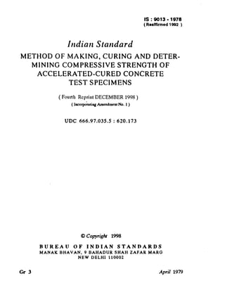
6. IS I 9013 - 1978
2. APPARATUS
2.1 Mould
-
The mould shall conform to IS : 516-1959*.
2.2 Mould Cover Plate - Each mould shall be provided with a flat steel
cover plate, rigid enough so as to avoid distortion during use and of
dimensions such that the plate completely covers the top edge of the
mould.
2.3 Curing
Tank
2.3.1 The curing tank shall be constructed from any material of
suitable strength that will resist the effects of corrosion.
The internal
dimensions of the tank shall be adequate to accommodate the required
number and size of the test specimens such that test specimens can be
easily removed.
2.3.2 The tank shall contain sufficient water and be controlled so that
the temperature of the water around the specimens immersed in the tank
is maintained at the desired level at all times except for a period not
exceeding 15 minutes immediately after the immersion of a freshly made
specimen into the tank.
2.3.3 A typical diagrammatic layout of a tank suitable for accelerated
curing of test specimens is given in Fig. 1.
3. PREPARATION
OF TEST SPECIMENS
3.1 The preparation of test specimen including sampling of materials,
preparation of materials, proportioning, weighing, mixing, testing for
workability, choice of the size of test specimens, compacting, and capping
of specimen shall be in accordance
with IS: 516-1959*,
if tests are
intended to draw correlation curve between the results from compressive
strength tests on specimens cured by normal curing method and accelerated
curing method.
3.2 If the tests are intended for control purposes, sampling shall be done
in accordance with IS : 1199-1959t and choice of the size of test specimens,
compacting, and capping of specimen shall be in accordance
with
IS : 516-1959*.
3.3 Immediately after moulding, each specimen shall be covered with a
steel plate thinly coated with mould oil to prevent adhesion of concrete.
4. ACCELERATED
CURING
BY WARM WATER
METHOD
4.1 After the specimens have been made, they shall be left to stand
undisturbed in their moulds in a place free from vibration at a temperature
*Methods of tests for strength of concrete.
*Methods of sampling and analysis of concrete.
5
7. SWITCH
GEAR
AND FUSES
I
L
a
DRAIN TAP/
050
NOTE- The dimensions (I, band
m and 0.65 m respectively.
c of curing tank suitable for accommodating
twelve, 150 mm cubes are 1.60 m,
Fro. 1 DIAGRAMMATIC
LAYOUTOF SUITABLE
CURINGTANK
8. of 27 f 2°C for at least one hour, prior to immersion in the curing tank.
The time between the addition of water to the ingredients
and immersion
of the test specimens in the during tank shall be at least 14 hours but shall
not exceed 34 hours.
4.2 The specimens in their moulds shall be gently lowered into the curing
tank and shall remain totally immersed at 55 f 2°C for a period of not
less than 19 hours 50 minutes.
The specimens shall then be removed from
the water, marked
for identification,
removed
from the mouldr and
immersed
in the cooling tank at 27 f 2°C before the completion
of
20 hours 10 minutes from the start of immersion in the curing tank. They
shall remain in the cooling tank for a period of not less than one hour.
NOTE-For control purposes, the above time tolerances may IX relaxed and
an appropriate correction factor applied.
5. ACCELERATED
5.1
free
and
time
CURING
BY BOILING
WATER
METHOD
After the specimens have been made, they shall be stored in a place
from vibration,
in moist air of at least 90 peqcent relative humidity
at a temperature
of 27 f 2’C for 23 hours f 15 minute
from the
of addition of water to the ingredients.
5.2 The specimens shall then be gently lowered into the curing tank and’
The
shall remain totally immersed for a period of 3# hours f 5 minutes.
temperature
of the water in ihe curing tank shall be at boiling ( 100°C )
at sea level.
The temperature
of water
shall not dro
more than
3°C after the specimens
are placed and shall return to go iling within
15 minutes.
NOTE - In confined places the temperature of the water may be kept just below
the boiling point to avoid excessive evaporation.
5.3 After suiing for 3) hours f 5 minutes in-the curing tank, the specimen
shall be. removed from the boiling water, removed fro&e
moulds and
cooled -by immersing
in cooling tank at 27 f 2°C for 2 h.
6. TE6TING
6.1 The specimens
shall be tested in accordance
with
IS : 516-1959*.
6.2 In the warm water method specimens shall be tested while still wet,
not more than 2 hours from the time of immersion in the coolitlg tank
6.3 In the boiling water
hours f 20 minutes.
method,
the age at the time of test shall be 28;
*&4etbodr of tests for strength of concrete.
7
9. 7. CALCULATION
7.1 The calculation
with IS : 5161959”.
of compressive
strength
shall be done in accordance
8. REPORT
8.1 The following information
shall be included in the report on each test
specimen :
mark (including
the size and type ) of test speci4 Identification
mens and date of casting;
b) Date and time of test and age of specimen;
Particulars
of concrete from which test specimen was made;
Method of compaction;
Size of specimen;
f-1 Mass of specimen;
g) Defects, if any, in specimen;
h) Time of adding water to concrete materials;
j> Time of making test specimen;
4 Time of immersion of test specimen into curing tank;
4 Time of remova of test specimen from curing tank;
4 Time of immersion of test specimen into cooling tank;
P) Time of removal of test specimen from cooling tank;
record of temperature
of water in curing tank;
9) Thermographic
Maximum
load at crushing;
r)
strength; and
s) Compressive
t) Description
of fractured face.
4
4
4
9. PRECAUTIONS
9.1 The following precautions
shall be taken :
a) The curing tank shall be cleaned and the water renewed periodically so as to prevent accumulation
of detritus which may impair
the heating or circulating
system.
b) The use of boiling water imposes the need for
prevent scalding or eye-burns,
resulting
from
steam, upon opening the cover. Also care shall
immersing the specimens to avoid splashing of
*Methods
of tests for strength
of concrete.
8
safety measures to
sudden escape of
be exercised when
hot water.
10. c) Strict attention shall be given to the protection and storage oft&
specimens during tAe initial period of curing.
d) Suitable safety devices and indicators shall be provided with the
set up. A separate panel or switch-board
shall be provided
incorporating the thermograph and related heating equipment
controls.
10. INTERPRETATION OF RESULTS
10.1 Since strength requirements in existing specifications are not based
upon accelerated curing, results from this method in checking the compliance of specified strengths at later ages shall be applied with great
caution.
10.2 The results can be used in rapid assessment of variability
control and signalling the need for indicated adjustments.
for process
10.3 The magnitude of the strength values from strength tests is influenced
by the specific combination of materi&
Therefore the use of the results
from either conventional tests at any arbitrary age or those from this
method shall be supported by experience or correlations developed for the
existing local conditions and materials ( see Appendix A ).
APPENDIX
A
( ClausesO. and 10.3 )
CORRELATION
OF RESULTS FROM COMPRESSIVE
TESTS ON SPECIMENS
CURED BY NORMAL
ACCELERATED
CURING METHODS
STRENGTH
AND
A-l. Accelerated curing of concrete hastens the process of hydration of
cement and as a result, a substantial proportion of the strength to be
attained in 28 days under normal curing conditions is achieved within a
shorter time. The rate and extent of hydration of cement under a particular curing regime depend mainly upon the chemical composition of
cement, water-cement ratio and mix proportions, which are considered to
be important parameters in the correlation of results from compressive
strength tests on specimens cured by accelerated curing method and normal
curing method.
The accelerated curing regime, in itself, is another variable in that
the higher temperature employed may alter the morphology of the hydration products apart from thermally activating the chemical reactions of
hydration of cement,
9
11. IS t 9019 - i978
A-2. The variability arising from the curing regime to be adopted, is
eliminated by standardizing them, as is-done in this standard.
Figures 2
and 3 (see Note ) show typical results on the correlation of compressive
strength of concrete specimens normally cured and accelerated-cured by
the Boiling Water Method and the Warm Water Method respectively.
It
is found that a correlation exists between the results obtained on concrete
specimens, cured by accelerated method and cured by normal method, for
It is also found
mixes employing different materials and mix proportions.
that the strength of concrete after accelerated curing ( by either method)
is of the order of 50 percent of that obtained on normally cured, 28 days
old specimens. When results of concrete with specific ingredients and mix
proportions are considered, the dispersion of results is considerably
CURING
I
10
20
30
ACCELERATED
CYCLE
3*5hZ
5min
I
I
I
40
50
60
STRENGTH
:
N/mn?-R.
Fro. 2 TYPICAL RELATION BETWEEN ACCELERATEDAND 28-DAY
COMPRESSIVE
STRENCJTH CONCRETE( BOILINGWATER METHOD)
OF
10
12. IS I 9919
-
1978
reduced, and the coefficient of variation of results from accelerated curing
methods may, in that case, be expected to be of the same order as
obtained in normally cured, 28 days conventional tests. Although the
tests have shown that the correlation between results from accelerated
curing method and normally cured 28 days conventional tests is not
materially affected by the chemical composition, fineness and strength of
cements, the mix proportions or use of some indigenous admixtures, it is
preferable to establish the actual correlation under site conditions for the
specific materials and mix proportions to be adopted, for use in each case.
NOTE-The typical correlationcurves given in Fig. 2 and 3 are based on a
reries testsconductedat the Cement Research
of
Institute India, New Delhi.
of
70
REGRESSION
EQUATION
R26=12*65+Ra
1.5
TO 3.5h
---w
ACCELERATED
-1h
STRENGTH
N/mr/-Ra
Fm. 3 TYPICAL RELATIONBETWEENACCELERATED
AND ~~-DAY
COMPRESSIVE
STRENGTH CONCRETE( WARM WATER METHOD )
OF
11
13. ts I 9913 - 1978
( C0tiinudfrom @ge 2 )
Concrete Subcommittee,
BDC 2:2
Mtmbers
Swm
C. R. ALIMCHANDANI
SHRI M. C. TANDON (
Stup Consultants Ltd, Bombay
Aitmate)
SHRI D. CHAKRAVARTY
Engineers India Ltd, New Delhi
Designs and Standards Organization
D E P u T Y DIRECTOR, STANDARDS Research
( Ministry of Railways ), Lucknow
(B&S)
ASSISTaNT
DIRECTOR,
STANDARDS ( M/C ) ( Alternate)
Engineering Research Laboratories, Hyderabad
DIRECTOR
DIRECTOR ( C & MDD )
Central Water Commission, New Delhi
DEPUTY DIRECTOR ( C & MDD )
( Alnmatc )
SHRI V. K. GHANEKAE
Struc;oylkrtgineering
Research Centre ( CSIR ),
Sanr A. S. PRASADA RAO ( Alfcmnte )
Central Road Research Institute (CSIR ), New
Dn R. K. GROSH
Delhi
SRRI M. R. CHATTERJEE ( Alfanate )
Engineer-in-Chief’s
Branch, Army Headquarters,
SHRI V. K. GUPTA
New Delhi
SHRI S. V. TI~ARE ( Alternate )
Associated Consulting Services, Bombay
Snnr J. S. HIN~ORANI
SHRI A. P. REMEDIOS ( Altanntc )
The Associatd Cement Companies Ltd, Bombay
SIIRI P. J. JA~WS
Suar M. R. VINAYAKA ( A&male )
National Buildings Organization, New Delhi
SHXI G. C. MATIZUR
Snnr G. T. BHIDE ( Alternate)
capacity
( ‘ Rammalaya ’ II
First
In personal
SHRI K. K. NAI+~BIA~
Crescent Park Road, Gandhinogar, Adyar, Madras )
Roads
Wing
( Ministry
of
Shipping
and
SHRI N. S. RAMASWAMY
Transport )
SHRI R. P. SIKI~A ( Alfemate )
Gammon India Ltd, Bombay
S~IRI T. N. S. RAO
SHRI S. R. PINHEIRO ( Alfcrnate )
Public Works and Housing Department, Bombay
SBRI M. P. GAJAPATHY RAO
SUPERINTENDING E N Q I N E E R, Central Public Works Department, New Delhi
DELHI CENTRAL CIRCLE No. 2
SHRI S. G. VAIDYA ( Alfcrnate )
Central Building Research Institute ( CSIR ),
DR C. A. TANEJA
Roorkee
SHRI B. S. GUPTA ( Altemate)
The Concrete Association of India, Bombay
SHRI B. T. UNWALLA
SHRI T. M. MENON ( Altmtatc)
Cement Research Institute of India, New Delhi
DR H.C. VISVESVARAYA
DR A. K. MULLICK ( Altematc)
12
14. BUREAU OF INDIAN STANDARDS
Headquarters:
Manak Bhavan, 9 Bahadur Shah Zafar Marg, NEW DELHI 110002
Telephones: 323 0131, 323 3375,323 9402
Fax : 91 11 3234062,91 11 3239399,91 11 3239382
Telegrams : Manaksanstha
(Common to all Offices)
Telephone
Central Laboratory:
Plot No. 20/9, Site IV, Sahibabad Industrial Area, Sahibabad 201010
Regional
Central
‘Eastern
8-77 00 32
Offices:
: Manak Bhavan, 9 Bahadur Shah Zafar Marg, NEW DELHI 110002
: l/14 CIT Scheme VII M, V.I.P. Road, Maniktola, CALCUTTA 700054
32376 17
337 86 62
Northern : SC0 335-336, Sector 34-A, CHANDIGARH 160022
60 38 43
: C.I.T. Campus, IV Cross Road, CHENNAI 600113
f Western : Manakalaya, E9, Behind Marol Telephone Exchange, Andheri (East),
235 23 15
Southern
832 92 95
MUMBAI 400093
Branch Offices:
‘Pushpak’, Nurmohamed Shaikh Marg, Khanpur, AHMEDABAD 380001
5501348
$ Peenya Industrial Area, 1st Stage, Bangalore-Tumkur Road,
BANGALORE 560058
839 49 55
Gangotri Complex, 5th Floor, Bhadbhada Road, T.T. Nagar, BHOPAL 462003
554021
Plot No. 62-63, Unit VI, Ganga Nagar, BHUBAWESHWAR 751001
40 36 27
Kalaikathir Buildings, 670 Avinashi Road, COIMBATORE 641037
21 01 41
Plot No. 43, Sector 16 A, Mathura Road, FARIDABAD 121001
8-28 88 01
Savitri Complex, 116 G.T. Road, GHAZIABAD 201001
8-71 1996
53/5 Ward No. 29, R.G. Baiua Road, 5th By-lane, GUWAHATI 781003
54 11 37
5-8-56C, L.N. Gupta Marg, Nampally Station Road, HYDERABAD 500001
201083
E-52, Chifaranjan Marg, C-Scheme, JAIPUR 302001
37 29 25
117/418 B, Sarvodaya Nagar, KANPUR 208005
21 68 76
Seth Bhawan, 2nd Floor, Behind Leela Cinema, Naval Kishore Road,
LUCKNOW 226001
23 69 23
NIT Building, Second Floor, Gokulpat Market, NAGPUR 440010
52 51 71
Patliputra Industrial Estate, PATNA 800013
26 23 05
Institution of Engineers (India) Building 1332 Shivaji Nagar, PUNE 411005
32 36 35
T.C. No. 140421, University P.O. Palayam, THIRUVANANTHAPURAM
621 17
695034
*Sales Office is at 5 Chowringhee Approach, P.O. Princep Street,
CALCUTTA 700072
27 10 85
tSales Office is at Novelty Chambers, Grant Road, MUMBAI 400007
309 65 28
*Sales Office is at ‘F’ Block, Unity Building, Narashimaraja Square,
BANGALORE 560002
222 39 71
Printed
al Simco
Printing
Press. Delhi