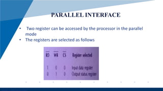
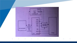
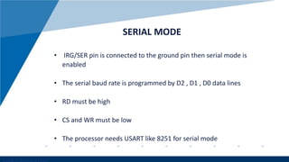
8295 
PRINTER CONTROLLER CHIP
• 8295 is a dot matix printer controller 
• It provides an interface for microprocessors such as 
www.company.com 
8085 and 8086 with dot matrix printers lr7040 
• The 8295 is packaged in a 40 pin dip 
• It can operate both in parallel mode and serial mode 
with 8085 and 8086 
• 8295 includes a 40 character buffer . when the buffer 
is full or a character return is received a line is printed 
automatically 
• The mode selection is parallel by default
www.company.com 
PARALLEL INTERFACE 
• Two register can be accessed by the processor in the parallel 
mode 
• The registers are selected as follows
Two types of data can be written in the input data 
register by the processor : 
1.The command to be executed 
2.The character data to be stored in the character 
buffer for printing 
www.company.com
• 8295 status is available in the output status 
www.company.com 
register at all times. 
• If IBF=1 no data should be written to 8295 
• DE = 1 , it is in DMA mode 
• IRQ/SER pin is used an as interrupt in parallel 
mode
www.company.com 
• 8257 IS THE DMA CONTROLLER 
• CONTROL SIGNALS BETWEEN DMA AND PROCESSOR – 
HOLD ,HLDA ,RD AND WR 
• CONTROL SIGNALS BETWEEN 8295 AND PROCESSOR – 
CS , RD ,WR ,RESET AND IRQ/SER 
• CS , RD, WR PINS ARE USED TO SELECT INPUT OR 
OUTPUT REGISTER 
• 8295 CONTROL SIGNALS FOR THE PRINTER INCLUDE MOT 
, PFM , STB , PFEED AND HOME 
•
www.company.com
www.company.com 
SERIAL MODE 
• IRG/SER pin is connected to the ground pin then serial mode is 
enabled 
• The serial baud rate is programmed by D2 , D1 , D0 data lines 
• RD must be high 
• CS and WR must be low 
• The processor needs USART like 8251 for serial mode

8295

  • 1.
  • 2.
    • 8295 isa dot matix printer controller • It provides an interface for microprocessors such as www.company.com 8085 and 8086 with dot matrix printers lr7040 • The 8295 is packaged in a 40 pin dip • It can operate both in parallel mode and serial mode with 8085 and 8086 • 8295 includes a 40 character buffer . when the buffer is full or a character return is received a line is printed automatically • The mode selection is parallel by default
  • 3.
    www.company.com PARALLEL INTERFACE • Two register can be accessed by the processor in the parallel mode • The registers are selected as follows
  • 4.
    Two types ofdata can be written in the input data register by the processor : 1.The command to be executed 2.The character data to be stored in the character buffer for printing www.company.com
  • 5.
    • 8295 statusis available in the output status www.company.com register at all times. • If IBF=1 no data should be written to 8295 • DE = 1 , it is in DMA mode • IRQ/SER pin is used an as interrupt in parallel mode
  • 6.
    www.company.com • 8257IS THE DMA CONTROLLER • CONTROL SIGNALS BETWEEN DMA AND PROCESSOR – HOLD ,HLDA ,RD AND WR • CONTROL SIGNALS BETWEEN 8295 AND PROCESSOR – CS , RD ,WR ,RESET AND IRQ/SER • CS , RD, WR PINS ARE USED TO SELECT INPUT OR OUTPUT REGISTER • 8295 CONTROL SIGNALS FOR THE PRINTER INCLUDE MOT , PFM , STB , PFEED AND HOME •
  • 7.
  • 8.
    www.company.com SERIAL MODE • IRG/SER pin is connected to the ground pin then serial mode is enabled • The serial baud rate is programmed by D2 , D1 , D0 data lines • RD must be high • CS and WR must be low • The processor needs USART like 8251 for serial mode