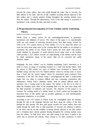
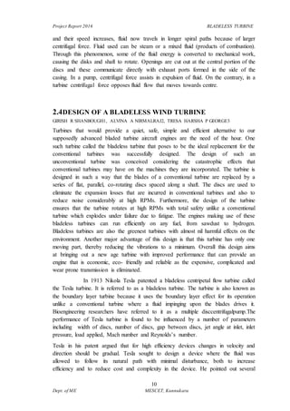
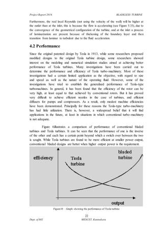
Project Report 2016 BLADELESS TURBINE
1
Dept. of ME MESCET, Kunnukara
CHAPTER 1
INTRODUCTION
Tesla turbine, a bladeless turbine, was patented by thefamous scientist Nikola Tesla
(1856–1943) in 1913. Up to now, a major stumbling block in its commercial use has
been its low efficiency and certain other operational difficulties. However, there has
been a resurgence of research interest in this type of turbines because they have
several advantages and hence may be appropriately developed and used in certain
niche application areas. In this article, an analytical theory has been developed for
predicting the performance of Tesla turbines, which agree well with experimental
results. The Tesla turbine is also known as disc turbine because the rotor of this
turbine is formed by a series of flat, parallel, co-rotating discs, which are
closelyspaced and attached to a central shaft. The working fluid is injected nearly
tangentially to the rotor by means of inlet nozzle. The injected fluid, which passes
through the narrow gaps between the discs, approaches spirally towards the exhaust
port located at the centreof each disc. The viscous drag force, produced due to the
relative velocity between the rotor and the working fluid, causes the rotor to rotate.
There is a housing surrounding the rotor, with a small radial and axial clearance.
Tesla turbine has several important advantages: it is easy to manufacture, maintain
and balance the turbine, and it has high power to weight ratio, low cost, significant
reduction in emissions and noise level, a simple configuration which means an
inexpensive motor. Tesla turbine can generate power for a variety of working media
like Newtonian fluids, non- Newtonian fluids, mixed fluids, particle laden two phase
flows (many aspects of two-phase flow. This turbine has self-cleaning nature due the
centrifugal force field. This makes it possible to operate the turbine in case of non-
conventional fuels like biomass which produce solid particles. It also suggests that
this bladeless turbine can be well suited to generate power in geothermal power
stations.Tesla turbo-machinery can also be used as a compressor by modifying the
housing and powering the rotor from an external source. Moreover, it can operate
either in the clockwise or anticlockwise direction. However, a Tesla disc turbine has
not yet been used commercially due to its low efficiency and other operational
difficulties.Further research and modification of Tesla turbine were temporarily
suppressed after the invention of gas turbine which was much more efficient than
Tesla turbine. From 1950 onwards both theoretical and experimental research on
Tesla turbine, Tesla pump, Tesla fan and Tesla compressor has been
regenerated.Quite a number of analytical models for theconventional configuration of
Tesla turbine have been developed. Among all these approaches available in the
literature, bulk parameter analysis, truncated series substitution methodology, integral
method,and finite difference solutions are worth mentioning. Solutions are mainly
Project Report 2016 BLADELESS TURBINE
2
Dept. of ME MESCET, Kunnukara
available for incompressible flows although there are some papers containing
solutions for compressible flows.
After the success of Whittle and von Ohain, the gas turbine became the centerpoint of
research and development and the understanding of its performance and optimization
has reached quite a mature stage. The understanding of the performance of Tesla
turbines is not nearly as thorough. The present authors would argue that the
development of a reliable and comprehensive (and yet simple, if possible, for practical
engineering use) mathematical theory is an important step towards developing the
necessary understanding of the fluid dynamics of the Tesla disc turbine. The objective
of the present work is to formulate a mathematical theory for a Tesla turbine,
developed in the appropriate cylindrical co-ordinate system. The geometric and flow
configuration for the present study is chosen to be the same as that given in Lemma et
al.because they provide data from their recent experiments which can be used to
verify the mathematical model and for the claimed superiority in its performance.
Their experimental results show that this particular configuration of Tesla turbine has
an isentropic efficiency of about 18–25% which is achieved by Musing rotor with
only nine discs (diameter 0.05 m) and compressed air as the working fluid. More
details about the configuration are discussed later. Deamet al.25 have attempted to
develop a simple analytical model for the configuration given in Lemma et al.,
considering incompressible and one dimensional flow. A limitation of their theory is
the absence of the radial flow feature. Moreover, their theory can only predict the no-
loss maximum efficiency of the turbine (assuming the fluid is flown through a duct
with uniform cross section between a pressure reservoir and the atmosphere). In their
theory25 the no-loss maximum efficiency is attainable when the rotor velocity is
equal to the velocity of the working fluid. This, however, does not happen in reality
because, if there is no relative velocity between the disc-rotor and the working fluid,
the viscousdrag force will be zero and in consequence, there will be no power output.
The scope of the present work is to develop an analytical model for a more realistic
case considering three-dimensional flow and consequences of the viscous drag force.
The model can compute the three-dimensional variation of the radial velocity,
tangential velocity and pressure of the fluid in the flow passages within the rotating
discs. Differential equations as well as closed-form analytical relations have been
derived. The present mathematical model can predict torque, power output and
efficiency over a wide range of rotational speed of the rotor.
1.1 Need of the Study/Project
There is undoubtedly a need for low-cost, low-maintenance, reliable power generators
in the < 10 kW range. This range covers three distinct groups of applications:
residential and remote renewable energy projects range from about 50 W to 10 kW,
small mobileand unmanned aerial vehicle (UAV) applications need power in the W to
100 W range,and power scavenger applications use μW to W. Tesla turbines are well-
Project Report 2016 BLADELESS TURBINE
3
Dept. of ME MESCET, Kunnukara
suited for these applications. Prior theoretical work has claimed greater than 80%
efficiency butexperimental turbines have also reported less than 30% efficiency
Current publications do not adequately address the practical design methodology and
effect on performance of the turbines’ input specifications, proposed hardware, and
operating parameters. To date, no comprehensive work covers scaling constraints and
performance trade-offs when attempting to engineer small (~2 cm3) Tesla friction
turbines. The motivation behind the present research is therefore to fill this gap, which
it does in two ways:
1) by recommending design guidelines and scaling methodologies for micro to small
scale Tesla turbines with power output in the range of 1 mW to 10 kW
2) by providing tools to generate a set of turbine design specifications and
performance sensitivities for a given range of inputs.
With such design methodologies in place, Tesla turbines can become ideal power
generators for renewable and mobile power applications.
Low-power applications target residential users and remote-village users, for
whomcapital and maintenance costs are the deciding factors. Tesla turbines can be
locallyLow-power applications target residential users and remote-village users, for
whom capital and maintenance costs are the deciding factors. Tesla turbines can be
locallymanufactured due to their simple structure and affordability, and because they
do not have vanes in the fluid path they are more suitable for mixed flows and
particulatemediums. Modularization is also straightforward, which is an important
consideration in remote areas where the flow rate changes drastically throughout the
year and from place to place. Further, unloaded Tesla rotors cannot exceed a
maximum speed due to centrifugal force, and are therefore safer.
1.2 Scope and Existing Technologies
However, a Tesla disc turbine has not yet been used commercially due to its low
efficiency and other operational difficulties. Further research and modificationof
Tesla turbine were temporarily suppressed after the invention of gas turbine which
was much more efficient than Tesla turbine. From 1950 onwards both theoretical and
experimental research on Tesla turbine, Tesla pump, Tesla fan and Tesla compressor
has been regenerated. Quite a number of analytical models for the conventional
configuration of Tesla turbine have been developed. Among all these approaches
available in the literature, bulk parameter analysis, truncated series substitution
methodology, integral method,and finite difference solutions are worth mentioning.
Solutions are mainly available for incompressible flows although there are some
papers containing solutions for compressible flows.Currently the field of micro-
turbine is an active research area; the bladeless Tesla turbine because of its simplicity
and robustness of structure, low cost and comparatively better operation at high rpm
may become a suitable candidate for this application. For this to happen the efficiency
Project Report 2016 BLADELESS TURBINE
4
Dept. of ME MESCET, Kunnukara
of the Tesla turbine, however, has to be improved. Researchers are attempting to
achieve this by modification of the configuration of the conventional Tesla turbines.
Shortly after Tesla had presented his turbine design, Allis-Chalmers Manufacturing
Company built three modelswith diameters of five feet and 500 kW capacities. They
operated at 3600 rpm and reached a maximum capacity of 38% mechanical
efficiency. Significant warping of the disks was witnessed. The project was stopped at
this time with the main objections being the high rotational speeds and the lack of
robustness of the disks (North, 1969). In 1977, a 10-month pilot generation project
had been conducted using the Tesla turbine design for the use in a hot salt-water
mixture resource in Imperial Valley, CA, USA. The sub-surface turbine operated 24
hours per day. At the end of the investigation the turbine was dismantled and
inspected for damage or wear due to particulate matter in the effluent. It was found
that erosion was minimal and no repair or replacement of components was required
(Jacobson, 1991). The Tesla turbine concept has recently been adapted to wind
turbines. The design includes an airfoil shaped spacer near the perimeter of the disk to
induce lift and add further torque to the rotating shaft (Fuller, 2010).
Project Report 2016 BLADELESS TURBINE
5
Dept. of ME MESCET, Kunnukara
CHAPTER 2
LITERATURE SURVEY
2.1 Designand Operation of Tesla Turbo machine - A state of the art
review
HARIKISHAN GUPTA E., SHYAM P. KODALI
Turbomachines are machines that transfer energy between a rotor and a fluid,
including both turbines and compressors. While a turbine transfers energy from a
fluid to a rotor, a compressor transfers energy from a rotor to a fluid. Many
different designs of turbomachines are in use of which Tesla turbomachine is one,
whose design is different from conventional designs. A Tesla turbomachine
utilizes the viscous shear forces of a fluid (boundary layer effect) passing near a
disk on an axle to transmit torque to and from the fluid. Tesla turbomachines have
found wide ranging applications that include handling of mixtures of solids,
liquids and gases without damaging the machine. It can be designed to efficiently
pump highly viscous fluids as well as low viscous fluids. It has been used to pump
fluids including ethylene glycol, fly ash, blood, rocks, live fish and many other
substances. This paper attempts to present the outcomes of research carried out by
various researchers during the last four decades. A summary of the modeling,
simulation, and experimental procedures used to understand Tesla machines is
presented. The performance of Tesla machines is found to be influenced by a
number of parameters including width of disks, the number of disks, gap between
disks, jet angle at inlet, inlet pressure, load applied, Mach number, Reynolds
number. The paper also outlines the results of investigations performed by the
researchers and further identifies the deficiencies, which can serve as a future
direction to research in this field.
Turbomachine applications have several alternatives, each of which emanates to
help build the world of power. One of these ideas was put forward by Nikola
Tesla, through his patent on ‘The Tesla turbine’ in 1913, which he referred to as a
bladeless turbine or friction turbine. The principle of Tesla turbine comes from
two main rudiments of physics: Adhesion and Viscosity, instead of the
conventional energy transfer mechanism in traditional turbines. It is referred to as
a bladeless turbine because it uses the boundary layer effect and not a fluid
impinging upon the blades as in a conventional turbine. The Tesla turbine is also
known as the boundary layer turbine, cohesion-type turbine, and Prandtl layer
turbine (after Ludwig Prandtl). If a similar set of disks and housing with an
Project Report 2016 BLADELESS TURBINE
6
Dept. of ME MESCET, Kunnukara
involute shape (versus circular for the turbine) are used, the device can be used as
a pump. The important point of this Tesla turbine invention is that the turbine does
not use friction in the conventional sense; rather it avoids it, and uses adhesion
(the Coandă effect) and viscosity instead. It utilizes the boundary layer effect on
the disc blades. Tesla turbine comprises of a multiple-disk rotor contained in a
housing provided with nozzles to supply high-speed moving fluid that is nearly
tangential to the rotor. The fluid flows spirally inward and finally exhausts from
the rotor through holes or slots in the disks near the shaft as shown in Figure 1.
The fluid drags on the disk by means of viscosity and the adhesion of the surface
layer of the fluid. In the process, the fluid slows down and adds energy to the
disks, thereby causing the rotation of rotor before it spirals into the center exhaust.
As a pump or compressor, fluid enters the rotor through holes near the shaft, flows
spirally outward, and exhausts from the rotor into a diffuser as. In this
configuration (when used as a pump) a motor is attached to the shaft causing
rotation of the multiple-disk rotor. The fluid enters near the center, takes the
energy from the disks, and then exits at the periphery.
Figure 1
After the initial focus on the new invention in the beginning of 20th century, very
little research went into understanding Tesla turbines until the revival of interest in
the 1950s. With the development and availability of computing facilities people
started working on using simulation studies to better understand the behavior of
these machines. Many attempts have been made to commercialize these machines,
but have found little success mainly owing to the small overall efficiencies due to
considerable losses in the nozzles when used as turbines and the diffuser or volute
when used as pumps. Most designs of Tesla turbomachinery are based on intuition
Project Report 2016 BLADELESS TURBINE
7
Dept. of ME MESCET, Kunnukara
and simple calculations or empirical experience, and much work needs to be done
in studying these losses with well defined scientific procedures in achieving
optimized nozzle and diffuser designs.
2.2Tesla Turbine for Pico Hydro Applications
Bryan P. Ho-Yan
Rural electrification is needed to improve the livelihoods of individuals that are
locatedwhere centralized power grids do not reach. Pico hydro, hydro systems of 5
kW capacity orless, can address this need at relatively low cost and with virtually no
negative environmentalor social impacts. An alternative and less complex design for a
pico hydro generator rotor,proposed by Nikola Tesla, uses the viscosity of fluids to
efficiently transfer the fluid energyto the rotor, resulting in useable work. Numerous
analytical and experimental investigationshave been performed to characterize the
flow within the Tesla turbine design. It has beenfound that efficiencies reported by
Tesla have not been reproduced by others. Inefficiencies are often attributed to the
losses due to flows through the nozzle and outlet. Tesla turbineswill not be considered
competitive in the general market until efficiencies surpass that ofconventional
designs and power densities can be improved. That said, the relatively simpledesign
of the Tesla turbine lends itself well to small scale power projects since it can be
easilymanufactured and maintained locally. Debris in water sources is a significant
concern insmall scale hydro systems. The disk rotors are not sensitive to abrasion and
can continue toperform under these types of flows. A preliminary design of a Tesla
turbine for pico hydroapplications has been undertaken employing Rice’s analytical
method. The investigationyielded a design capable of generating 300 W under
conditions of 20 m head and 2.5 L/sflow. The efficiency of the preliminary turbine
design was near 80% but it is believed thatthe bulk of efficiency losses will be found
in inlet and exhaust flows, which are notconsidered in this analysis. Challenges
remain for the application of Tesla turbines to picohydro generation.
Hydro power is driven by extracting the potential energy from water over a height
difference. The energy in thewater is converted to mechanical energy and can be used
directly or converted again into electrical energy by means of a generator. The term
head, H, is the measure of pressure in the water. It refers to the actual height
difference the water travels. Power, P is the energy converted over time or the rate of
work being done.
The power that can be extracted from the water can be calculated with the following
formula:
P=ηQHρ g
whereη is efficiency, Q is total volumetric flow, ρ is density, and g is gravity.
Different types of turbines can be selected to best suit given heads and flows. Two
main families of turbinesinclude impulse and reaction type turbines.
Project Report 2016 BLADELESS TURBINE
8
Dept. of ME MESCET, Kunnukara
Impulse turbines - Pressurized water is converted to high-speed water jets that transfer
the kinetic energy by impacting the turbine blades or buckets causing rotation. Since
the water jet acts in the open, the casing essentially acts as a splash guard. Examples
of impulse turbines include Pelton wheel, Turgo wheel and Michell-Banki(crossflow)
turbines.
Reaction turbines –
Water flow is directed to create a pressure difference across the blades to create lift to
rotate the turbine. Examples of reaction turbines include Kaplan and Francis turbines.
Tesla Turbine-
For the application of pico hydro, several designs can beutilized. Common designs
incorporate mechanisms such as pistons, paddles, vanes, and blades. An
unconventional design was patented by Nikola Tesla in 1913 with the objective to
develop a turbine with lower complexity, cost, andmaintenance requirements than
conventional mechanisms. Within the literature, the Tesla turbine has been commonly
referred as a boundary layer, multiple-disk, friction, or shear force turbine (Rice,
2003). The design consists of several, closely-spaced rigid disks set in parallel on a
shaft. The co-rotating disks are centred and locked to the shaft. Located near the
centre of the disks are orifices that allow forfluid exhaust in the axial direction. The
disk-shaft assembly isset onbearings and enclosed within a cylindrical casing. An inlet
into the casing is directed approximately tangentially.
Figure 2
The working fluid enters the chamber through the inlet in the tangential direction and
flows along the surface ofthe disk through the disk spacings. The flow path spirals
Project Report 2016 BLADELESS TURBINE
9
Dept. of ME MESCET, Kunnukara
towards the centre orifices, then exits axially through the outlet. Due to viscosity, the
fluid adheres to the disks with the no-slip condition occurring directly adjacent to the
disk surface and a velocity gradient forming throughout the working medium away
from the surface. Through this phenomenon, some of the fluid energy is converted to
mechanical work, causing the disks and shaft to rotate.
2.3Experimental Investigation of Tesla Turbine and its Underlying
Theory
Kartikeya Awasthi#1, AmanAggarwal*2
Nikola Tesla is widely known for his outstandingachievements in generation
transmission and utilization of power. The object of this paper is to experimentally
verify one such method of extracting electrical power from fluid energy; devised by
Tesla in his 1913 patent; known as Tesla Turbine. It is to be noted that almost no
work has been done using water as the working fluid for the turbine so an attempt to
reconstruct the turbine as per Nikola Tesla’s patent has been made with positive
results obtained by generation of useful electrical power using water as the medium
which provides a new outlook towards our understanding of the turbines and the ways
by which mechanical energy of the motive fluid can be converted into useful
electrical output.
Intriguingly, the term ‘turbine’ can be deluding inexplaining Tesla’s innovation as it
tends to create an image of something mounted on a shaft with fan-like blades. With
the advent of 20th century two types of turbines were developed to harness the
fuel/fluid energy and they were the ‘bladed turbines’ driven by moving water or steam
from a head and the ‘piston engines’ driven by pressurized gases produced from
combustion of the fuel. The former being a rotaryengineand the latter a reciprocating
engine had one thing in common difficult and time consuming construction plus
maintenance. Nikola tesla’s ‘bladeless turbine’ built on entirely different mode of
operation was a turning point in this regard. The turbine is the first of its kind to
utilize the boundary layer effect of the propelling fluid over the rotor discs along with
the fluid properties of adhesion and viscosity. The objective of this project is to
construct the working model of a turbine based on Tesla’s patent and investigate the
theoretical basis of this turbine and its possible application in rural electrificationby
independent installation or as a hybrid.
According to the 1913 patent of Nikola Tesla; the workingfluid enters the chamber
through the inlet in the tangential direction and flows along the surface of the disk
through the disk spacing. The flow path spirals towards the centre orifices, then exits
axially through the outlet. Due to fluid properties of viscosity and adhesion it adheres
to the disks with the no-slip condition occurring directly adjacent to the disk surface
and a boundary layer velocity gradient forming throughout the working medium away
from the surface. As fluid slows down and adds energy to the discs, it spirals to the
centre due to pressure and velocity, where exhaust is. As disks commence to rotate
Project Report 2016 BLADELESS TURBINE
10
Dept. of ME MESCET, Kunnukara
and their speed increases, fluid now travels in longer spiral paths because of larger
centrifugal force. Fluid used can be steam or a mixed fluid (products of combustion).
Through this phenomenon, some of the fluid energy is converted to mechanical work,
causing the disks and shaft to rotate. Openings are cut out at the central portion of the
discs and these communicate directly with exhaust ports formed in the side of the
casing. In a pump, centrifugal force assists in expulsion of fluid. On the contrary, in a
turbine centrifugal force opposes fluid flow that moves towards centre.
2.4DESIGN OF A BLADELESS WIND TURBINE
GIRISH R SHANBOUGH1, ALVINA A NIRMALRAJ2, TRESA HARSHA P GEORGE3
Turbines that would provide a quiet, safe, simple and efficient alternative to our
supposedly advanced bladed turbine aircraft engines are the need of the hour. One
such turbine called the bladeless turbine that poses to be the ideal replacement for the
conventional turbines was successfully designed. The design of such an
unconventional turbine was conceived considering the catastrophic effects that
conventional turbines may have on the machines they are incorporated. The turbine is
designed in such a way that the blades of a conventional turbine are replaced by a
series of flat, parallel, co-rotating discs spaced along a shaft. The discs are used to
eliminate the expansion losses that are incurred in conventional turbines and also to
reduce noise considerably at high RPMs. Furthermore, the design of the turbine
ensures that the turbine rotates at high RPMs with total safety unlike a conventional
turbine which explodes under failure due to fatigue. The engines making use of these
bladeless turbines can run efficiently on any fuel, from sawdust to hydrogen.
Bladeless turbines are also the greenest turbines with almost nil harmful effects on the
environment. Another major advantage of this design is that this turbine has only one
moving part, thereby reducing the vibrations to a minimum. Overall this design aims
at bringing out a new age turbine with improved performance that can provide an
engine that is economic, eco- friendly and reliable as the expensive, complicated and
wear prone transmission is eliminated.
In 1913 Nikola Tesla patented a bladeless centripetal flow turbine called
the Tesla turbine. It is referred to as a bladeless turbine. The turbine is also known as
the boundary layer turbine because it uses the boundary layer effect for its operation
unlike a conventional turbine where a fluid impinging upon the blades drives it.
Bioengineering researchers have referred to it as a multiple disccentrifugalpump.The
performance of Tesla turbine is found to be influenced by a number of parameters
including width of discs, number of discs, gap between discs, jet angle at inlet, inlet
pressure, load applied, Mach number and Reynolds’s number.
Tesla in his patent argued that for high efficiency devices changes in velocity and
direction should be gradual. Tesla sought to design a device where the fluid was
allowed to follow its natural path with minimal disturbance, both to increase
efficiency and to reduce cost and complexity in the device. He pointed out several
Project Report 2016 BLADELESS TURBINE
11
Dept. of ME MESCET, Kunnukara
important factors affecting performance, including that increasing size and speed
increases the efficiency, as does decreasing the disc spacing. He also mentions that
centrifugal pressure gradients, increasing with the square of velocity, prevent the
device from running away to high speeds and thus preventing the device from
damage. Conventional turbines suffer a major drawback in practical applications
because of their low efficiencies. Their efficiency is lowered by the use of moving
blades to generate shaft power. Thus failure of a single blade results in inadequate
expansion which directly affects the overall efficiency of the turbine. On the contrary
Tesla turbine consists of a set of smooth disks, with nozzles applying a moving gas to
the edge of the disc. The gases drag on the disc by means of viscosity and the
adhesion of the surface layer of the gas. As the gas slows and adds energy to the discs,
it spirals into the center exhaust and causes rotation of the discs.Thus minimizing the
expansion losses and increasing the efficiency of the prime mover.
2.5Design and Computational Analysis of 1KW Tesla Turbine
Raunak Jung Pandey*1, Sanam Pudasaini1, Saurav Dhakal1, RangeetBallav Uprety1, Dr. Hari
PrasadNeopane1
Conventional turbines are mostly reaction and impulse type or both. Often technical
challenge faced by conventional turbines in Himalaya is erosion by sediment.
Financial feasibility of power plants is depended upon innovations to prevent erosion
of mechanical equipments or alternatives which better handle these conditions. Tesla
turbine is an unconventional turbine that uses fluid properties such as boundary layer
and adhesion of fluid on series of smooth disks keyed to a shaft. It has been garnering
interest as Pico turbine where local communities could manage such stations in low
capital. It provides a simple design which can be produced locally and maintained at
low cost. It can be useful in plants for pumping of water and other viscous fluids.
Tesla Turbine pump has been used as a blood pump. Due to its uniqueness it has its
own cliché uses giving importance to identify the scope of use of Tesla Turbine in
Nepal. This paper is presented in context of research project at Kathmandu
University to understand working of Tesla Turbine. For this design and computational
fluid dynamics (CFD) analysis of 1 kW tesla turbine was carried out. The models thus
created were used for computational analysis. The proposed uses of Tesla Turbine in
Nepal have been suggested.
Tesla Turbine is a bladeless turbine consists of a series of discs with nozzle
through which gas or liquid enters towards the edge of the disc. Momentum transfer
between fluid and disc takes place due to fluid properties of viscosity and adhesion.
Discs and washers, that separate discs, are fitted on a sleeve, threaded at the end and
nuts are used to hold thick end-plates together. The sleeve has a hole that fits tightly
on the shaft. Openings are cut out around center of the discs to communicate with
exhaust ports formed in the side of the casing. Hence tesla turbine is described as a
multi disc; shear force or boundary layer turbo machinery that works with
Project Report 2016 BLADELESS TURBINE
12
Dept. of ME MESCET, Kunnukara
compressible and incompressible fluid. Fluid enters radially and exits axially through
the ports. Tesla turbine has advantages of ease of production, versatility and low
maintenance. Fluid used can be steam or water. It is unaffected by sediment erosion
due to lack of vanes. A challenge related to Tesla turbine is low efficiency. Tesla
turbine claims high rotor efficiency for optimum design, but experimentally many
difficulties has been found to achieve high efficiencies in nozzles and rotors. The
design of a 1 kW Tesla turbine was carried using iterative process for head and
discharge for main dimensions of the turbine.
CHAPTER 3
HISTORY
Project Report 2016 BLADELESS TURBINE
13
Dept. of ME MESCET, Kunnukara
One of the inventions that the engineer and inventor Nikola Tesla
conceived was the Tesla disk turbine. With this device he proposed to make an useful
and efficient handle of the energy especially on electric generation, fluid power and
engines field. Therefore, the Tesla turbine also called and denoted in literature as
Tesla turbomachines, multiple-disk, shear, shear force or boundary layer
turbomachinery, is a rotatory fluids machine that works with compressible and
incompressible fluid. The direction of the fluid flows in the radial and tangential
direction, forming spirals streamwise and operates principally on the laminar regime.
He referred to it as a thermodynamic converter in his original patented.
More over of conceiving the Tesla turbine, Nikola Tesla provided an useful design for
other machines operating the principle of the Tesla disk. Examples of these machines
are an air compressor, an air motor engine, a vacuum exhauster or vacuum pump.
These machines use the Tesla method of “fluid propulsion” that is based on two basic
principals of physics of the fluids: “adhesion and viscosity”. These types of
turbomachinery can be applied as liquid pumps, liquid or vapor or gas turbines, and
gas compressors.
On October 21
st
, 1909 Nikola Tesla filled a patent for a pump, which uses
smooth rotating disks inside a volute casing. In the patent (which he received May
6
th
, 1913, U.S. Patent No.1,061,142) Tesla began by pointing out the benefits of a
smooth transition of energy:
"In the practical application of mechanical power based on the use of fluid as the
vehicle of energy, it has been demonstrated that, in order to attain the highest
economy, the changes in velocity and direction of movement of the fluid should be as
gradual as possible."
The Tesla turbine invention was discussed in the semitechnical press at the
time of the invention. What Tesla claims in his patents was a high efficiency due to
the form of energy transfer, based on the assumption that a highest economy will be
attained when the changes in velocity and direction of the movement of the fluid is as
gradual as possible. This can be accomplished causing the propelling fluid moving in
natural paths or streamlines of least resistance, free from constraints and disturbances
caused by vanes or intricate devices in common turbomachinery, and changing the
fluid velocity and direction of movement by imperceptible degrees.
Besides, the employment of the usual devices for deriving energy from a fluid, such a
pistons, paddles, naves and blades, necessarily introduces numerous limitations,
constraints and adds to the complication, cost of production and maintenance of the
machines.The idea of Tesla, was to incorporate this turbine to the Wandercliff project
where he expected to deliver a low cost energy for popular use. Then, his first
prototypes were big in size, and the success for high power was not achieved; the
Allis Chalmers Company also bet for this design and built a friction turbine, and later
ceased their tests because of the low efficiency obtained for big sizes and early
problem with the materials .
Project Report 2016 BLADELESS TURBINE
14
Dept. of ME MESCET, Kunnukara
Figure 3 American patent No. 1,061,206 of Tesla turbine
The Tesla turbine is also known as disc turbine because the rotor of this turbine is
formed by a series of flat, parallel, co-rotating discs, which are closely spaced and
attached to a central shaft. The working fluid is injected nearly tangentially to the
rotor by means of inlet nozzle. The injected fluid, which passes through the narrow
gaps between the discs, approaches spirally towards the exhaust port located at the
centre of each disc. The viscous drag force, produced due to the relative velocity
between the rotor and the working fluid, causes the rotor to rotate. There is a housing
surrounding the rotor, with a small radial and axial clearance.
Tesla turbine has several important advantages: it is easy to manufacture,
maintain and balance the turbine, and it has high power to weight ratio, low cost,
significant reduction in emissions and noise level, a simple configuration which
means an inexpensive motor. Tesla turbine can generate power for a variety of
Project Report 2016 BLADELESS TURBINE
15
Dept. of ME MESCET, Kunnukara
working media like Newtonian fluids, non- Newtonian fluids, mixed fluids, particle
laden twophase flows (many aspects of two-phase flow may be found ). This turbine
has self-cleaning nature due the centrifugal force field. This makes it possible to
operate the turbine in case of non-conventional fuels like biomass which produce
solid particles. It also suggests that this bladeless turbine can be well suited to
generate power in geothermal power stations.Tesla turbo-machinery can also be used
as a compressor by modifying the housing and powering the rotor from an external
source. Moreover, it can operate either in the clockwise or anticlockwise direction.
However, a Tesla disc turbine has not yet been used commercially due to its
low efficiency and other operational difficulties. Further research and modification of
Tesla turbine were temporarily suppressed after the invention of gas turbine which
was much more efficient than Tesla turbine. From 1950 onwards both theoretical and
experimental research on Tesla turbine, Tesla pump, Tesla fan and Tesla compressor
has been regenerated. Quite a number of analytical models for the conventional
configuration of Tesla turbine have been developed. Among all these approaches
available in the literature, bulk parameter analysis, truncated series substitution
methodology, integral method,and finite difference solutions are worth mentioning.
Solutions are mainly available for incompressible flows although there are some
papers containing solutions for compressible flows.
Currently the field of micro-turbine is an active research area; the bladeless
Tesla turbine because of its simplicity and robustness of structure, low cost and
comparatively better operation at high rpm may become a suitable candidate for this
application. For to happen the efficiency of the Tesla turbine, however, has to be
improved. Researchers are attempting to achieve this by modification of the
configuration of the conventional Tesla turbines.
After the success of Whittle and von Ohain, the gas turbine became the
centerpoint of research and development and the understanding of its performance
and optimization has reached quite a mature stage. The understanding of the
performance of Tesla turbines is not nearly as thorough. The present authors would
that the development of a reliable and comprehensive (and yet simple, if possible, for
practical engineering use) mathematical theory is an important step towards
developing the necessary understanding of the fluid dynamics of the Tesla disc
turbine.
The objective of the present work is to formulate a mathematical theory for a
Tesla turbine, developed in the appropriate cylindrical co-ordinate system. The
geometric and flow configuration for the present study is chosen to be the same as
that given in Lemma et al. because they provide data from their recent experiments
which can be used to verify the mathematical model and for the claimed superiority in
its performance. Their experimental results show that this particular configuration of
Tesla turbine has an isentropic efficiency of about 18–25% which is achieved by
using rotor with only seven discs (diameter 0.02 m) and compressed air as the
working fluid.
Project Report 2016 BLADELESS TURBINE
16
Dept. of ME MESCET, Kunnukara
CHAPTER 4
Project Report 2016 BLADELESS TURBINE
17
Dept. of ME MESCET, Kunnukara
PROBLEM DEFINITION
4.1 PRINCIPLE
4.1.1BoundaryLayer
In Tesla turbine the effects of boundary layer are of main importance and through the
boundary layer occurs all the change of energy. Figure and Figure depict the
formation of a boundary layer near the leading edge of the boundary layer and its
transition to turbulent.
Fluid dynamic forces depend in a complex way on the viscosity of the fluid. As the
fluid moves,the molecules right next to the surface stick to the surface. The molecules
just above the surface are slowed down in their collisions with the molecules sticking
to the surface. These molecules in turn slow down the flow just above them. The
farther one moves away from the surface, the fewer the collisions affected by the
object surface. This creates a thin layer of fluid near the surface in which the velocity
changes from zero at the surface to the free stream value away from the surface. This
layer is what is called the boundary layer because it occurs on the boundary of the
fluid. In reality, the effects of vortices and instabilities are three-dimensional.
Figure 4Schematic representation of laminar and turbulent boundary layer.
Boundary layers may be either laminar (layered), or turbulent (disordered) depending
on the value of the Reynolds number. For lower Reynolds numbers, the boundary
Project Report 2016 BLADELESS TURBINE
18
Dept. of ME MESCET, Kunnukara
layer is laminar and the streamwise velocity changes uniformly in the direction away
normal to the wall, as shown on the left side of the Figure . For higher Reynolds
numbers, the boundary layer is turbulent and the streamwise velocity is characterized
by unsteady swirling flows inside the boundary layer, as shown on the right side of
the Figure 4. Besides Figure 4 shows the boundary layer thickness and the
displacement thickness of the boundary layer _, which its solution for a flat plate are
due to Blausius.
The plots showed in Figure 5 are only for laminar built up layer, they are plotted until
the transitional Reynolds number.
Figure 5
For Figure 5 can be stated that with higher velocities the thickness of the boundary
layer is lower, and the critical point (end of the line plot defined by the critical
Reynolds of transition Rextr) starts nearer to the leading edge. Moreover the boundary
layer for the air is thicker than for the water due to the fact that the air has a lower
kinematic viscosity than the air.
Project Report 2016 BLADELESS TURBINE
19
Dept. of ME MESCET, Kunnukara
Generally, the thickness of a turbulent boundary layer is larger than that of a laminar
boundary layer owing to the greater energy losses and mixing transports in the
turbulent layer. At the outer region of the rotor of the turbine the local average
velocity is lower than at the outlet, then formation or build up of boundary layer is
present at the beginning, and transition to turbulent happens when the flow
accelerates. In conclusion both laminar and turbulent boundary layers, with present of
a core external flow (external to the boundary layer), are present inside the rotor of the
turbine. The external flow reacts to the edge of the boundary layer just as it would to
the physical surface of an object.
The order of magnitude of all the terms in momentum equations at of order of
magnitude equal to the thickness of the boundary layer because the region of external
flow is minimum, and the boundary layer is in order of magnitude equal to the gaps
between disks in the rotor of the turbine, then all the terms in NS equations have to be
solved, and analytical exact solution does not exist for turbulent flow, so the most
powerful tool nowadays is the CFD tool. However it is important to highlight that the
tool is not so powerful for flows in transition region.
4.1.2LaminarFlow
Laminar flow is also referred to as streamline or viscous flow. These terms are
descriptive of the flow because, in laminar flow, layers of fluid flowing over one
another at different speeds with virtually no mixing between layers, fluid particles
move in definite and observable paths or streamlines, and the flow is characteristic of
viscous fluid or is one in which viscosity of the fluid plays a significant role.
Figure 6 Fluid Sheared between two plates
For a Newtonian fluid, with constant viscosity, the shear stress is proportional to the
shear strain rate or in other terms to the gradient of velocity normal to the wall.
Project Report 2016 BLADELESS TURBINE
20
Dept. of ME MESCET, Kunnukara
τ =μ ɗv/ɗy
For no-slip wall conditions, Fluent uses the properties of the flow adjacent to the wall
boundary to predict the shear stress on the fluid at the wall. In laminar flows this
calculation simply depends on the velocity gradient at the wall.
The Reynolds number for flow in pipe, with length scale as the diameter, has the
following ranges:
Laminar flow ReD < 2,000
Transition flow 2,000 < ReD < 2,000
Turbulent flow ReD > 4,000
4.1.3 Turbulence
For stationary, incompressible and turbulent flow will be used. Turbulence
is defined as an eddy-like state of fluid motion where the inertial-vortex forces are
larger than any other forces that tend to damp them out. Turbulent flow is
characterized by the rapid, and random fluctuations of field variables that lay over a
more or less mean value due to the decay large instabilities. This fluctuation will
affect the path of the particles travelling in irregular paths with no observable pattern
and no definite layers. There is no definite frequency as there is in wave motion.
4.1.4 Transition
Transition is not an easy issue, generally is treated as a 2D, steady phenomenon
proceeding in the direction from laminar to turbulent, but it is actually much more
complex; it is a stochastic, 3D, unsteady process which may proceed in either forward
(laminar to turbulent) or reverse direction (turbulent to laminar). Roughly describing,
transition is the intermediate flow between laminar and turbulent, the transition starts with
some bursting process as depicts the Figure 4.9. The subsequent growth of the unstable
waves and their breakdown into turbulence is not so well understood and a little detail of
the actual process itself is known, but there have been many experiments and transition
correlations.
Figure 7Transition from laminar to turbulent
Project Report 2016 BLADELESS TURBINE
21
Dept. of ME MESCET, Kunnukara
Depending upon the case laminar or turbulent the friction factor will vary and different
values of torque are expected as the shows, in a modification of the Moody diagram. The
localization of the design point is with a very low Reynolds number in the laminar range,
in order to have a high shear stress, or friction force over the walls of the disks.
Figure 8The flat plate Boundary layer (a) geometry with the boundary layer thickness and (b) typical
shear and heat flux distributions
Figure 9 Natural transition to turbulent over a flat plate
Project Report 2016 BLADELESS TURBINE
22
Dept. of ME MESCET, Kunnukara
Furthermore, the real local Reynolds (not using the velocity of the wall) will be higher at
the outlet than at the inlet, this is because the flow is accelerating (see Figure 5.33), due to
the convergence of the geometrical configuration of the turbine, and at the inlet a process
of laminarization are present because of thickening of the boundary layer and then
transition from laminar to turbulent due to the fluid acceleration.
4.2 Performance
Since the original patented design by Tesla in 1913, while some researchers proposed
modified designs to the original Tesla turbine design, some researchers showed
interest on the modeling and numerical simulation studies aimed at achieving better
performance of Tesla turbines. Many investigations have been carried out to
determine the performance and efficiency of Tesla turbo-machinery. Most of these
investigations had a certain limited application as the objective, with regard to size
and speed as well as the nature of the operating fluid. However, some of the
investigations have tried to establish the generalized performance of Tesla-type
turbomachines. In general, it has been found that the efficiency of the rotor can be
very high, at least equal to that achieved by conventional rotors. But it has proved
very difficult to achieve efficient nozzles in the case of turbines, and efficient
diffusers for pumps and compressors. As a result, only modest machine efficiencies
have been demonstrated. Principally for these reasons the Tesla-type turbo-machinery
has had little utilization. There is, however, a widespread belief that it will find
applications in the future, at least in situations in which conventional turbo-machinery
is not adequate.
Figure 6illustrates a comparison of performance of conventional bladed
turbines and Tesla turbines. It can be seen that the performance of one is the inverse
of the other and each has a certain point beyond which a switch over between the two
is sought. While Tesla turbines are found to be more efficient at smaller power output,
conventional bladed designs are better when higher output power is the requirement.
Figure10 : Graph showing the performance of Tesla turbine
Project Report 2016 BLADELESS TURBINE
23
Dept. of ME MESCET, Kunnukara
The performance and efficiency of the rotor of Tesla-type turbomachinery is found to
be dependent on the combination of not only parameters related to the rotor assembly,
but also on the efficiency of the nozzles and the nozzle-rotor interaction. The
performance of the pump is also strongly dependent on the interaction of the fluid
leaving the rotor with that in the volute and on the efficiency of diffusion in the
volute.
4.3 Parameters
Following is a list of various parameters that were identified and investigated by
researchers in arriving at better designs:
 Number of Disks
 Inner, outer radius, and thickness of the disks
 Gapsize
 Number and shape of the nozzle
 Incompressible or Non-incompressible flow
 Reynolds number
 Jet angle inlet
 Roughness of the disk
 Inlet pressure and Load applied
 Spacers geometry
 Flow medium and type of the flow
 Velocity of the flow
 Number of inlets
 Speed of the rotor
 Placement of outlet
 Type of the application
 Stator, bearing, spacer and rotor sealing’s
 Radius ratio
 Dynamic and Kinematic viscosity
 Stagnation and static pressure
 Angular velocity
 Total flow rate
4.3.1 Flow parameter
The flow parameter or flow coefficient is defined with the radial velocity at the
inlet reference to the tangential velocity of the disk, that is:
φ =u/ωro
An associated flow parameter useful for experiments analysis in which the
volumetric flow rate can me measured is:
φ =Q/2πrobω²
Project Report 2016 BLADELESS TURBINE
24
Dept. of ME MESCET, Kunnukara
4.3.2 Loading coefficient
The power deduced from the volume concept, the same known as the Eulerian
equation for turbomachinery, referenced to the circumferential velocity of the
disks, give us the loading coefficient:
λ =Pshaft/ṁV²d = Tω/ ṁV²d = roV1-riV2/ωro²
From the post processing of Fluent solution, can be extracted the integral values
as the momentum forces over surfaces, or mass averaged values of the tangential
velocity at the outlet.
4.3.3 Efficiency
As it was mentioned the efficiency is also function of the flow parameter η =
f(φ), and is defined for an incompressible flow as the loading coefficient to the
available energy of an isentropic expansion:
η = λ/Δhs=Pshaftρ/ṁΔp
4.4 Characterization of the Flow
It is established that a wide range of types (or regimes) of flow can occur
between corotating disks including wholly laminar flow, laminar flow with regions of
bursting process, wholly turbulent, laminar flow proceeding through reverse transition
or relaminarization from turbulent to laminar. There are experimental evidences
concerning these flows. In a descriptive way, the flow describes the following
behaviour: It is assumed that the flow enters in turbulent regime and at the leading
edge, starts the formation of the boundary layer, the thickening of the boundary layer
occupied all the gap between the disks and the viscous forces become predominant
over the inertial forces; the turbulence level is reduced due to the dissipation of
energyby means of viscous effects in the boundary layer, and the profile became
laminar.
Project Report 2016 BLADELESS TURBINE
25
Dept. of ME MESCET, Kunnukara
Figure 11Laminarization and transition modes present in the gap.
After the boundary layer build up, the forward transition to turbulent appears caused by the
increase of velocity. Then, the fluids accelerates in the radial direction and the thickness of
boundary layer decreases, appearing again the inviscid zones where inertial forces are
predominant and turbulence is expected to increase but with high acceleration the flow vortex
in the turbulent boundary layer became stretched and the vorticity is dissipated through the
viscous effects, this process is called reverse transition or relaminarization.
4.5 Reversibility of Operation
This term reversibility does not refer to thermodynamically reversibility, rather it
refers to the clockwise or counterclockwise operation, just changing the valve
configuration at the inlets and the same rotor can be used in clockwise or counter
clockwise direction. Besides, the same rotor can be used for turbines or pumps taking
into account some variation of his geometrical dimensions and the type of working
fluid. That is, as a turbine the multiple-disk rotor is contained in a housing provided
with nozzles to supply high-speed fluid approximately tangential to the rotor. The
fluids flows spirally inward and finally exhaust from the rotor through holes near the
shaft. As a pump or compressor, fluid enters the rotor through holes near the shaft,
flows spirally outward and exhaust from the rotor into a diffuser such as a volute
scroll. For reversibility it is necessary, as was mentioned, different nozzles und valves
for fluid controls.
4.6 Losses
In general any flow behaviour that reduces the efficiency of a
turbomachine is called loss and this dissipation of energy can be defined in terms of
entropy increase.
The low efficiency presented by this machine can be explained using the definition of
entropy creation valid for adiabatic by Denton :
S= m.s= -∫1/T.V.F dVol
Where V is the local flow velocity and F is the local viscous force vector, and shows
that the entropy creation is likely to be high in regions where high velocities coincide
with high viscous forces as it present in the inner rgion of the disks. Moreover with
higher mass flow the total entropy creation is also higher.
The mechanism for entropy creation are:
 Viscous friction in either boundary layer or free shear layer.
 Heat transfer across finite temperature differences.
Project Report 2016 BLADELESS TURBINE
26
Dept. of ME MESCET, Kunnukara
 Non-equilibrium processes such as occur in very rapid process
The first mechanism include all the losses in the rotor and the losses due to the
interaction between the fluid and the solid components of the turbine and the viscous
force acting in every particle of fluid –not only the drag on the solid boundaries–, the
second can be neglected if no change of temperature is assumed (for example in the
third turbine that Rice tested), and the third mechanism occurs in the nozzle and at the
outlet of the rotor, where strong changers of areas appears.
Figure 12Turbine loss model is categorized into head loss, shaft power loss that are part of the turbine
hardware and operation and other losses that are more implementation dependent. These loss estimates
are applied to our turbine model, and turbine performance is evaluated for various flow profiles.
4.6.1 Inner the rotor:
Interaction of the fluid with the solid components: Since the principle of working is
the viscous effect in the boundary layer concept the friction through the gap plays an
important roll; it is very know that in most boundary layers the velocity changes most
rapidly near the surface; then, most of the entropy generation is concentrated at the
inner part of the layer. In turbulent boundary layers the generation of entropy occurs
within the laminar sublayer and the logarithmic region referring to the universal law
wall function. This effect is present in the gap, moreover this loss can be extend to the
energy dissipated due to shear forces on the outer interaction of the fluid between the
housing and the fluid.
Project Report 2016 BLADELESS TURBINE
27
Dept. of ME MESCET, Kunnukara
On the leading edge and trailing edge exist also the creation of entropy. On the
leading edge exist an effect of admission blockage caused by finite thickness of the
disks, and second at the trailing edge, it is presented, because of the change of
geometry and also the trailing edge acts as a mixing process.
The high swirling rotation near the axis increase the viscosity effects and it is also a
reason of the entropy increment.
Union and spacers elements: Contributes to the disturbances of the field and the losses
due to drag when the fluid pass around the elements.
Partial Admission: The partial admission is due to the finite numbers and nozzles,
when fully peripheral admission is not present, some ventilations behaviours and
differences in the radial and tangential gradient of velocity generating non-symmetry
of the fluid and increasing the viscosity effects in such a manner they not contribute to
the torque of the rotor.
4.6.2 Outer the rotor:
Losses of available energy due to irreversibility of the nozzles that supply the fluid to
the rotor. Losses of available energy in the exhaust process due to uncontrolled
diffusion. The change of flow direction from radial to axial involves a 90° bend,
which causes stronger secondary flows; besides the flow at the outlet has a high
swirling flow.
Mechanical losses from bearings and seals; can be defined a mechanical efficiency for
the shaft and its components. Leakage, small part of fluid leaks trough the bearing and
seals and is fluid that no contributes to the amount of torque in the rotor. A volumetric
efficiency can be defined. The patent of Nikola Tesla uses a labyrinth seals for
reducing the leakage trough the outside.
4.7Swirling and Rotating Flows
Because of the symmetry respect to the axis, which the rotor spins, the model can be
built using a domain with 2D mesh and with the three components of velocity in the
space. Fluent model the flow in 2D and include the prediction of the circumferential
(or swirl) velocity. The method is not useful for model where circumferential
gradients are present but this fact does not imply a non-zero swirl velocities.
In swirling flows, conservation of angular momentum tends to create a free vortex
flow, in which the circumferential velocity, v, increases sharply as the radius r
decreases, and diminishing his value until at r(0) = 0, where viscous forces begin to
dominate. A tornado is one example of a free vortex. Figure 4.7 shows the radial
distribution of v in a typical free vortex, making quite difficult to simulate the flow for
inner regions. But with the presence of the wall rotating at a constant ω_, angular
speed, the motion of the walls tends to induce a force vortex motion to the fluid.
Project Report 2016 BLADELESS TURBINE
28
Dept. of ME MESCET, Kunnukara
4.8 Theory of Operation
The working fluid enters the chamber through the inlet in the tangential direction and
flows along the surface of the disk through the disk spacings. The flow path spirals
towards the centre orifices, then exits axially through theoutlet.Due to fluid properties
ofviscosity and adhesion it adheres to the disks with the no-slipcondition occurring
directly adjacent to the disk surface and a boundary layer velocity gradient forming
throughout the working medium away from the surface. As fluid slows down and
adds energy to the discs, it spirals to the centre due to pressure and velocity, where
exhaust is. As disks commenceto rotate and their speed increases, fluid now travels in
longer spiral paths because of larger centrifugal force. Fluid used can be steam or a
mixed fluid (products of combustion). Through this phenomenon, some of the fluid
energy is converted to mechanical work, causing the disks and shaft to rotate.
Openings are cut out at the central portion of the discs and these communicate directly
with exhaust ports formed in the side of the casing. In a pump, centrifugal force
assists in expulsion of fluid. On the contrary, in a turbine centrifugal force opposes
fluid flow that moves towards centre.
Project Report 2016 BLADELESS TURBINE
29
Dept. of ME MESCET, Kunnukara
CHAPTER 5
METHODOLOGY
5.1Experimental Setup
A. MaterialList
 The materials used to construct our water-driven experimental set
up are very economical and easy to find. It includes mild steel,
aluminium, P.V.C. pipe, and Acrylic (or Plexi) sheet.
 Mild steel 202 for rotor discs.
 Nozzle.
 Stainless steel washers as disc spacers.
 Aluminium for making shaft.
 Acrylic sheet and P.V.C. pipe for making the rotor
B.BuildingRotor
The rotor of the bladeless turbine consists of a series of circular discs with smooth
&polished surface. The number of discs for the rotor depends on the head available as
with increase in number of discs, initial torque of the turbine also increases due to
increase inertia of the system.
C. Building Stator
Stator forms the most important unit of any turbo-machinery. It forms the part on
which the rest of the unit i.e. rotor and the shaft rests. The following approach was
made to build the stator of our turbine:
 The ease of availability and the cost formed our basis for material selection for
the stator.
 P.P (polypropylene) 5”x5”x1 block was selected because it is light weight and
it is relatively easy to perform mechanical operations like drilling on it.
 Exhaust holes were made on an acrylic sheet of standard thickness. It was
ensured that these exhaust holes were made symmetrical to those present on
the disc so as to make an easy outward flow of the exhaust water and also to
reduce friction and stalling of water inside the casing resulting in the turbine to
stop rotating further.The acrylic sheet was mounted on the casing.
Project Report 2016 BLADELESS TURBINE
30
Dept. of ME MESCET, Kunnukara
D. Building Nozzle
A small copper pipe from the factory waste was used to design the nozzle for our
turbine. The pipe was bent into the duck mouth shape nozzle.
5.2 Design Parameters
Variable Measure Units
Outer radius, ro 50 mm
Inner radius, ri 10 mm
Disk spacing, b 3 mm
Angular velocity, Ω rpm
Outer velocity, vo m/s
Inner velocity, vi m/s
Flow rate, Q L/s
Total flow rate, Qt L/s
Total required pressure,
Δpt
kPa (m)
Project Report 2016 BLADELESS TURBINE
31
Dept. of ME MESCET, Kunnukara
Torque, T N·m
Power, P W
Efficiency, η %
Number of disks 7 units
Disk thickness 2 mm
Overall height 180 mm
Overall width 80 mm
Overall length 180 mm
Estimated mass 2 kg
5.3 Components
5.3.1Disc
5.3.2 Shaft
5.3.3 Acrylic sheet
5.3.4 Disc spacers andBrearings
5.3.5 Nozzle
The main is the inlet nozzle through which the propelling fluid is introduced, but if
reversibility of operation is desired (as a pump machine), a second inlet can be
installed in the inner ratio for the introduction of fluid in the opposite direction, and a
diffuser in the outlet.
5.3.6 PVC pipes, Nut and Bolts
Project Report 2016 BLADELESS TURBINE
32
Dept. of ME MESCET, Kunnukara
Project Report 2016 BLADELESS TURBINE
33
Dept. of ME MESCET, Kunnukara
CHAPTER 6
RESULTS AND DISCUSSIONS
It is possible to fabricate sub-cm Tesla turbines with commercially available
technologyto achieve over 40% mechanical efficiency. The rotor can be made
modular and stacked to meet the input flow rate without performance degradation,
and therefore this design is suitable for tailoring to residential and remote power
applications.Turbine performance is very sensitive to hardware and to operating
parameters, andthis is likely the reason for large discrepancies among the
performances of published turbines. By applying appropriate design constraints,
turbines can be designed with consistent performance. For the same input
specification, multiple designs are possible. A unified design tool can provide these
choices for turbine design, making it easier to manufacture and deploy optimized
turbines. This can extend the turbines’ operating range. Smaller-than-cm rotors might
require micro structuring of the discs to increase momentum transfer in order to
achieve power densities in the watt/cm³range. Open-loop systems will potentially
require filters that remove particulates in order to achieve power densities in the
watt/cm³range.To achieve higher than watt/cm3 power density, a fuel-based turbine
might be needed.
Rapidly increasing demands of the power generation are asking for fast development
in the area ofrenewable energies. The generation of home level energy and use of
distributed generation system is the key necessity of the present age. So the idea to
return back the out of market turbine again to the practical implementation will be a
great milestone in the way of achieving the green energy. For the revival to tesla
turbine it was necessary to withdraw its limitation. The new design of Bladeless
Turbineswhich uses both the pressure pull and the boundary layer effect, has been
proved very economical and efficient design and it can be used in the future to get rid
of the polluted power generation.Bladeless Turbines is a versatile turbine. It can be
used as pumped storage systems. It can be used as radial ventricular devices which are
‘gentle’ on blood pumps and doesn’t causes loss of platelets because of its energy
transfer mechanism. Bladeless pump has been reported to handle different kinds of
industrial and agricultural and waste fluids. It can also be alternative to Improved
Water Mill (IWM). It can be concluded that the study on Bladeless Turbines has
yielded important understanding of the turbine. The concept of a boundary-layer
turbine originated about a century ago, in the research of Nikola Tesla.Fluid
parameters describing the interaction of disc with fluid is studied .A high-velocity of
fluid is injected tangentially into the spaces between a stack of closely spaced discs,
flowing inwardly in a spiral toward a centrally located exhaust. The drag between the
surface of the discs and the fast moving fluid results in the conversion of fluid flow to
mechanical power. This turbine was invented in response to the problems with bladed
turbines and also with the intent to use it to help generate electricity from steam from
Project Report 2016 BLADELESS TURBINE
34
Dept. of ME MESCET, Kunnukara
geothermal sources. The construction permits free expansion and contraction of each
plate individually under the varying influence of heat and centrifugal force and
possesses a number of other advantages which are of considerable practical
importance. This turbine directly converts kinetic motion of the fluid into rotary
motion via the boundary layer effect and adhesion. The boundary layer turbine is
simple to build, maintain and modify. This turbine is safer in the case of disc/blade
failure or other parts failure, since the housing compartment or casing can be made
strong enough to contain broken or cracked discs and often the failure of one or more
discs will not necessarily lead to the failure of the entire turbine. This design is very
sturdy because the discs and rotor are bolted together and there is minimal wear
except on bearings. Also it does not suffer from cavitation or particulate problems that
many turbines and fans must deal with andcan work with a wide variety of working
fluids and over a wide range of temperatures. This turbine is an efficient self-starting
prime mover which may be operated as a steam or mixed fluid turbine at will, without
changes in construction and is on this account very convenient. In spite of all the
above mentioned advantages the boundary layer turbine is limited to small scale
application. However this turbine has the potential to eliminate all the disadvantages
of the present day conventional turbines in the near future. In order to achieve this the
design of the turbine will be modified slightly and an optimum design will be arrived
at.
The above results from the experimentation reflect the vast implications of the
bladeless turbine in the industry as well asother sectors such as rural electrification.
The results prove and make a benchmark in our understanding of the fluids and their
utilization at our disposal in the form of mechanical and electrical applications. The
conventional turbines have long been trying to eliminate the losses due to viscosity
and boundary layer formation but the present work experimentally proves the
successful utilization of these two fluid properties into an altogether new system;
namely ‘Bladeless Turbines’ with added benefits of reduced or no cost of blade
maintenance, simple and cheap construction with compact units at use. It is to be
noted that the peak efficiencies achieved in this analysis are relatively high compared
to thedocumented overall efficiencies of past Bladeless Turbines investigations. As
stated in the assumptions, losses due to flows in the inlet nozzle and exhaust are not
considered in this analysis and likely make up for the shortfall seen. That said, this
analysis can still be a useful tool towards optimizing the turbine design when used in
a comparative manner. Total required pressure for the preliminary design was in the
higher region for pico hydro systems which is in the realm of impulse type turbines,
such as Pelton or Turgo wheel designs. These designs are established technologies
and popular amongst users. The implication of operating under high head limits the
application to fewer sites that have water flows that can match this requirement. There
is no argument that the design is relatively simple, however to achieve appreciable
power generation, larger sized components are required. Material costs will increase
due to this, as will manufacturing costs since equipment must be sized to handle these
components.
Project Report 2016 BLADELESS TURBINE
35
Dept. of ME MESCET, Kunnukara
CHAPTER 7
ADVANTAGES
Use of different kind of exotics fluids, with particles, droplets, multiphase, etc.;
bladeless turbines can ingest liquids with solids particles in the working fluid or fuel
without damage. In geothermal applications can ingest the total effluent without heat
exchangers and or steam brine separators as are used in Kalina cycle process for
geothermal applications; besides, for pump case, a complete list of fluids and
materials that have been pumped successfully are reported by Possell, showing the
versatility of the bladeless of Tesla pump and the utility of Tesla turbine to handle
different kinds of fluids. Then, unlike conventional pumps and turbines that are easily
damaged by contaminants, the bladeless Tesla turbine or pump can handle particles
and corrosives in the flow as well as gases with particles or ash or high viscosity
fluids. Friction pumps are commercialized now by Discflo demonstrating its
feasibility for hard pumps fluids.with low noise but a high velocities vibrations can
appear and the rotor has to be manufactured carefully. With lower vibration, the
overall safety of the machine increases. Besides, it has proved good behaviour on
intermittent operation, shut off and rapid load variation.
The bladeless Tesla turbine engine can turn at much higher speeds with total safety. If
a conventional bladed turbine engine goes critical or fails, it will has exploding parts
slicing through hydraulic lines, control surfaces and maybe even personal. With the
bladeless Tesla turbine this is not a danger because it will not explode. If it does go
critical, the failed component will not explode but implode into tiny pieces, which are
ejected through the exhaust while the undamaged components continue to provide
thrust.
Destructive effects and deposition or impingement is no present in this machine due
to the principle of impulsion that uses the fluid characteristics of adhesion and
viscosity, and not pressure and impact as conventional turbines, which suffer high
structural loads with the differential pressure phenomena between the sides of a blade.
Another facility of the principle of the Tesla disk is the double clockwise and
anticlockwise direction of rotation in a single machine.
Besides, with the gradual change of direction of the velocity and also the fact that
flow separation is no presented because the fluid is accelerated in the flow between
corotating disks then unstable flow is no present with undesirable vibrations. With
these characteristics this machine can be operated at high velocities without
mechanical problems, speeds until 250,000 rpm in a turbine, were reported by Navy
of USA and angular speeds until 28,000 rpm in an oil pump were reported by Posell.
Considered from the mechanical standpoint, the turbine is astonishingly simple and
economical in construction, (low first costs) and by the very nature of its construction,
Project Report 2016 BLADELESS TURBINE
36
Dept. of ME MESCET, Kunnukara
(ease of balancing) should prove to possess such a better durability and freedom from
wear and breakdown than others, far in advance of any type of steam or gas motor of
the present day. The internal static pressure inside the housing is very low, for this
reason heavy cast housings are not necessary in order to assure its structural
resistance. Safety features of the bladeless devices are inherent in their design and
operation. Low vibration increases safety over the structural assembly. While
conventional turbines will overspeed to destruction without special sensors, bladeless
turbines has its own overspeed protection: As load is removed and the rotor begins to
gain speed the centrifugal force increases at a rate which is the square of the speed
and this force will equal the inward pressure.
Project Report 2016 BLADELESS TURBINE
37
Dept. of ME MESCET, Kunnukara
CHAPTER 8
DISADVANTAGES
Tesla turbomachinery proclaims high rotor efficiency for optimum design, but
experimentally has been found many difficulties to achieve high efficiencies in
nozzles and rotors, in the case of turbines, because of the high velocity of the fluid
when it flows through the inlet nozzle. This means that the performance of the overall
turbine is strongly dependent on the efficiency of the nozzle and the nozzle-rotor
interaction and its irreversibility. As a result, only modest machines efficiencies have
been demonstrated. Principally for these reasons the Tesla-type turbomachinery has
had little utilization.
In conventional bladed turbine the total losses are a fraction of the available energy.
This fraction increase rapidly when turbine size decreased because the losses are
proportional to the wetted area of the housing and static parts. For this reason,
multiple disks turbines are not competitive with conventional turbines over the major
portion of the power-size spectrum, because of the high velocity of the flow at outer
radius, in bigger turbines.
This turbine is a high-speed low-torque machine. Therefore, low performance is
achieved in applications with big sizes. The inertia of market to common engines,
lack of technology and understanding of friction turbine have impended the
development of this technology, then great producers of turbomachines must evaluate
the viability of this technology.
Project Report 2016 BLADELESS TURBINE
38
Dept. of ME MESCET, Kunnukara
CHAPTER 9
APPLICATIONS
 As a turbine to generate the power comparatively nearer/equal to the
conventional power generation techniques .
 As higher efficient motors with low wear, friction, warping) motors.
 As a pump to transfer not only liquids but also other materials like live fish,
ethylene glycol, fly ash, blood, abrasive, rocks, and biomass.
 For power generation instead of wind vanes.
 As impellers in the aerospace applications, nuclear power plants.
 As a Fuel Cell (miniature/micro-scale power generation systems).
 In hospitals for the transfer of blood, transfer of drugs at a controlled rate, etc.
 As a replica for steam turbines in aircrafts.
 As a pump for a high vacuum application.
 As a UPS (Unpredictable Power Supply) .
 Used in the places having limitations of diffuser and collector in other type of
turbines.
 Efficiency is maximized, when boundary layer thickness is approximately
equal to inter-disc spacing.
 Turbines of this design can operate at temperatures above 1000°C.
 Also be used in low temperature conditions (room temperature).
 It has only few moving parts (cheaper manufacture) and lubrication is
required only for shaft bearings (environmentally friendly).
 There is no loss of the inlet fluid which can be collected at the center of the
rotor.
Project Report 2016 BLADELESS TURBINE
39
Dept. of ME MESCET, Kunnukara
 In conventional pumps, fans, compressors, generators, circulators, blowers,
turbines, transmissions, various hydraulic and pneumatic systems.
 Used in naval applications.
 To produce a required pressure differential.
 As a centrifugal turbine (centrifugal reverse flow turbine).
 For desalinization of water and hydrogen generation.
 In self-starting applications.
 Transferring compressible, incompressible, Newtonian and non-Newtonian
fluids.
 In the fields having limitations of vibrations in the turbine.
 In the micro fabrication techniques to construct micro electro mechanical
systems (MEMS).
 To produce high vacuum.
 To derive motive power from steam.
 To achieve high rotational speeds even twice to the conventional turbine.
 As a Valvular Conduit.
 As ultra-small profile heat engines.
 In low pressure head flow.
 Used to eliminate unsteady, windage, partial admission, lacing wires and
exhaust losses.
 As a subsonic flow turbine.
 Power supply for mobile robots.
 In inkjet, printers, and fuel injectors.
 In problems involving fluid-structure interaction.
Project Report 2016 BLADELESS TURBINE
40
Dept. of ME MESCET, Kunnukara
 It can be used in Pico hydro applications.
 Biomass fuelled power plants
 Heat recovery installations
 Co-generation systems
 Systems using solar energy
 Plants with low temperature geothermal medium
 Installations where exhaust heat can be utilized.
Project Report 2016 BLADELESS TURBINE
41
Dept. of ME MESCET, Kunnukara
CHAPTER 10
FUTURE WORK
The Tesla turbomachines is worthy of further investigation, especially to understand flow
regimes and the complex process of transition.
Physical modeling of this machine is very useful, valuable and recommended in order to
assured the real efficiency of a machine of this type, while computational modeling as
well as analytical solutions will reveal good capabilities of flow modeling and would be a
good complement to the experimental research.
Some of the following topics would be interesting for further investigation:
 Compressible analysis of the Tesla turbine.
 Effect of the number of nozzles on the performance of the turbine.
 Optimization of the geometry, following analytical work of Lawn and Rice as
well as the experience gain through experimental work of Rice, and recently
Schmidt .
 Improvement of the numerical method in order to handle transitional flows as
well as evaluation of others turbulent models to use in the simulations.
When considered in conjunction with fabrication capabilities, this research provides
aguide to what is achievable in terms of scaling down these systems. It also provides
atool for exploring Tesla turbine operation. However, more work on disk micro
structuring is needed in order to enhance the friction coefficient and improve the
power density of the turbine as it scales down. More work on full admission need to
be investigated as losses due to partial admission increase as the rotor scales down.
Some of the losses are not modeled or derived, but estimated from published papers.
Mechanical to electrical conversion is not addressed in this research. A practical
implementation is needed to evaluate the turbine design tool for power generation and
to tailor it to a particular application. Though the research here focuses specifically on
water turbines, the design tool can be used for any fluid. Because Tesla turbines and
Tesla pumps operate on the same principle, the conclusions in this dissertation can
also be extended to Tesla pump specifications. A future step could additionally extend
the analysis here to compressible flow and to two-phase flows, which would
potentially enable solar CHP and CPVT implementations.
Project Report 2016 BLADELESS TURBINE
42
Dept. of ME MESCET, Kunnukara
CHAPTER 11
CONCLUSION
It is worth mentioning that the Tesla turbomachinery as a turbine, compressor, and
pump specially fits into those instances where compacted unities are required for
generating electrical power or transferring materials or pumping fluids are required as
in the case of isolated areas. It should be noticed that, as a unique source of rotating
motion of this type, Tesla machines can run under a very wide spectrum of not only
fuels but also fluids in general. Tesla-type turbomachinery probably cannot prove
competitive in an application in which more conventional machines have adequate
efficiency and performance. Thus, it cannot be expected to displace conventional
water pumps or conventional water turbines or gas turbines. Tesla-type
turbomachinery can be considered as source of standard in applications in which
conventional machines are inadequate. This includes applications for small shaft
power, or the use of very viscous fluid or non-Newtonian fluids. It is an advantage
that multiple-disk turbomachines can operate with abrasive two-phase flow mixtures
with less erosion of material from the rotor.
In general, it has been found that the efficiency of the rotor can be very high, at least
equal to that achieved by conventional rotors. But it has proved very difficult to
achieve efficient nozzles in the case of turbines, and efficient diffusion for pumps and
compressors. As a result, only modest machine efficiencies have been demonstrated.
Principally for these reasons the Tesla-type turbo-machinery has had little utilization.
There is, however, a widespread belief that it will find applications in the future, at
least in situations in which conventional turbo-machinery is not adequate. It can be
concluded that the study on Bladeless Turbines has yielded important understanding
of the turbine. The concept of a boundary-layer turbine originated about a century
ago, in the research of Nikola Tesla.Fluid parameters describing the interaction of disc
with fluid is studied .A high-velocity of fluid is injected tangentially into the spaces
between a stack of closely spaced discs, flowing inwardly in a spiral toward a
centrally located exhaust. The drag between the surface of the discs and the fast
moving fluid results in the conversion of fluid flow to mechanical power. This turbine
was invented in response to the problems with bladed turbines and also with the intent
to use it to help generate electricity from steam from geothermal sources. The
construction permits free expansion and contraction of each plate individually under
the varying influence of heat and centrifugal force and possesses a number of other
advantages which are of considerable practical importance.The flow in the Tesla
turbine was simulated with different geometrical models, as well as laminar and
turbulent approach. Since the flow itself is found in a transition regime with multiple
processes -as transition, relaminarization, recirculation, between other phenomena- an
exact simulation that full fills all the physical requirements is quite difficult to achieve
with CFD tool. Nevertheless both approximations are valid and they would show
Project Report 2016 BLADELESS TURBINE
43
Dept. of ME MESCET, Kunnukara
different features, characteristics and behaviour typical for each case and in extension
for the Tesla turbine. One of these differences is that the inflection point of radial
velocity profile presented in laminar solution disappears in the turbulence model, for
which the turbulent effects act as a mechanism of balanced in the axial direction. The
results show that multiple disk turbines are workable and feasible, in the engineering
sense, but they present a low efficiency in both laminar and turbulent cases; lower for
laminar case; the difference between these cases is significant. A good parameter for
evaluating the performance of the Tesla turbine is the loading coefficient, which
reflects the amount of torque obtained from the turbine. It is noticeable that for
turbulent case the amount of torque is higher, nearly the double, for which the total
viscosity is higher with the present of the turbulent viscosity. The concept used for
evaluating efficiency was the total-to-total efficiency.
Project Report 2016 BLADELESS TURBINE
44
Dept. of ME MESCET, Kunnukara
REFERENCES
[1] Nikola Tesla, “Fluid Propulsion” (Nikola Tesla Original patent), Pub. No.: US
1913/1,061,142.
[2] Scott Douglas O’Hearen, “Radial Turbine Blade System”, Pub. No.: US
2003/0053909 A1.
[3] Udo E. Effenberger, “Viscosity Impeller”, Pub. No.: US 1983/4,402,647.
[4] Salvatore F. Grande, “Bladeless Conical Radial Turbine and Method”, Pub. No.:
US 2007/7,192,244 B2.
[5] Tukeo S. Saitoh, “Centrifugal Reverse Flow Disk Turbine and Method to obtain
Rotational Power”, Pub. No.: US 2011/0164958 A1.
[6] Christopher Brewer, “Turbine”, Pub. No.: US 2007/0116554A1.
[7] Guisto Fonda-Bonardi, “Fluid Flow Control System”, Pub. No.: US
1983/4,372,731.
[8] Harold Leo EntricanJr, “Tesla Turbine”, Pub. No.: US 2002/0182054 A1.
[9] Robert Fleming, “Hybrid Electric Power Motor, System, and Vehicle”, Pub. No.:
US 2010/0293951 A1.
[10] Chester W. MarynowsKi, F. Michael Lewis, Charles E. Lapple, Robert
G.Murray, T. Semran, “Radially Staged Drag Turbine”, Pub. No.: US
1980/4,201,512.
[11] Ho-Yan, “Tesla Turbine for Pico Hydro Applications ,” Guelph Engineering
Journal pp. 1-8
[12] Jeffrey Stuart Allen, “A model for fluid flow between parallel, corating annular
disks ,” July 1990
[13] Ladino, “Numerical Simulation of the Flow Field in a Friction-Type Turbine
(Tesla Turbine),” Institute of Thermal Powerplants,Vienna University of Technology
[14] Rhetta, J.: “The Tesla Bladeless Pumps and Turbines”, Proceedings of the
Intersociety Energy Conversion Engineering Conference, Vol. 4. IEEE Piscataway,
NJ, USA,1991.
Project Report 2016 BLADELESS TURBINE
45
Dept. of ME MESCET, Kunnukara
[15] Miller, G. E.; Sidhu, A; Fink, R.; Etter, B. D. (1993). "July. Evaluation of a
multiple disk centrifugal pump as an artificial ventricle"
[16] Harikishan Gupta E.: “Design and Operation of Tesla turbo machine”,
International Journal of Advanced Transport Phenomena, Vol. 2, No 01, Jan Dec
2013.
[17] Nikola Tesla, 1913 Tesla patent 1,061,142 Fluid Propulsion.
[18]Nicola Tesla in British Patent 179,043
[19] Raunak Jung Pandey.: “Design and Computational Analysis of 1KWTesla
Turbine”, International Journal of Scientific and research Publication, Vol. 4, Issue11,
November 2014, ISSN 2250-3153
[20] Rice, W.: “An Analytical and Experimental Investigation of Multiple-Disk
Turbines”, Journal of Engineering for Power, Trans. ASME, series A, Vol. 87, No. 1
Jan. 1965, pp. 29-36
[21] N. Tesla. “Turbine" In: US Patent No. 1,061,206 (May 1913).
[22] W. Rice. “An Analytical and Experimental Investigation of Multiple Disk
Turbines"
[23] [Online] site links Available: https://energypedia.info/wiki/Pico_Hydro_Power
[24]Matsch, L., Rice, W.: “An Asymptotic Solution for Laminar Flow of an
Incompressible Fluid Between Corotating Disks”, Journal of Applied Mechanics, Vol.
35, Trans. ASME, Vol. 90 series E, March 1968, pp. 155-159.
[25]Mayle, R. E.: “The Role of Laminar-Turbulent Transition in Gas Turbine
Engines”, Transaction of the ASME 91-GT-261, Troy, New York, June 1991.
[26]Nendl, D.: „DreidimensionaleLaminareInstabilitätenbeiEbenenWänden”, Zamm
56, 1976, s. 211-213.
[27]Nendl, D.: „Reibungsturbine”, VDI –Berichte Nr. 193 1973, s. 287-293.
[28]Nendl, D.: „EinetheoretischeBetrachtung der Reibunsturbomaschinen von Nikola
Tesla“. Doktor-Ingenieurs Dissertation.LehrstuhlfuerTechnischeMechanik,
TechnischeHochschule Aachen, July 1966.
[29] O'Neill, John J. "Prodigal Genius: Biography of Nikola Tesla, USA, New York,
July 15, 1944.
Project Report 2016 BLADELESS TURBINE
46
Dept. of ME MESCET, Kunnukara
[30]Piesche, M.: „Berechnung der Kompressiblen, LaminarenUnterschallströmung in
einer Tesla Turbine”, Strömungsmechanik und Stromungsmachinen 28, 1980, s. 25-
31.
[31]Rhetta, J.: “The Tesla Bladeless Pumps and Turbines”, Proceedings of the
Intersociety Energy Conversion Engineering Conference, Vol. 4. IEEE Piscataway,
NJ, USA,1991.
[32] Rice, W.: “An Analytical and Experimental Investigation of Multiple-Disk
Turbines”, Journal of Engineering for Power, Trans. ASME, series A, Vol. 87, No. 1
Jan. 1965, pp. 29-36.
[33]Schetz A.J., Fuhs, a.e.: “Fundamental of Fluid Mechanics”, John Wiley and Sons
Inc, New York. 1999, ISBN 0-471-34856-2.
[34] Schmidt, Darren D.: “Biomass Boundary Layer Turbine Power System”,
California Energy Commission (CEC), EISG PROGRAM [online] Available from
Internet: <URL: http://eisg.sdsu.edu/Fullsums/00-06.htm ><URL:
http://eisg.sdsu.edu/shortsums/shortsum0006.htm>, 1991, California, USA. <URL:
http://eisg.sdsu.edu/Far/00-06%20FAR.pdf>
[35] Staged Bladeless Turbine Automobile, Partnership for a New Generation of
Vehicles, PNGV, Program US. [online] Available in internet:
<URL:http://www.geocities.com/vair65_2000>
[36]Tabatabai, M.: “On the Process of Inverse Transition in Radial Flow Between
Parallel Disks”, H. W. Liepmann, R. Narasimha, Turbulence Management and
Relaminarisation, Springer Verlag, Proceedings of the IUTAM Symposium Banglore,
India, 1987.
[37] Tesla, N.: “Turbine” United States Patent No. 1061206, May 6, 1913.
[38] “Tesla´s New Method of and Apparatus for Fluid Propulsion,” Electrical Rev.,
Sept. 9: 515-517 (1911)

6. Chapters

  • 1.
    Project Report 2016BLADELESS TURBINE 1 Dept. of ME MESCET, Kunnukara CHAPTER 1 INTRODUCTION Tesla turbine, a bladeless turbine, was patented by thefamous scientist Nikola Tesla (1856–1943) in 1913. Up to now, a major stumbling block in its commercial use has been its low efficiency and certain other operational difficulties. However, there has been a resurgence of research interest in this type of turbines because they have several advantages and hence may be appropriately developed and used in certain niche application areas. In this article, an analytical theory has been developed for predicting the performance of Tesla turbines, which agree well with experimental results. The Tesla turbine is also known as disc turbine because the rotor of this turbine is formed by a series of flat, parallel, co-rotating discs, which are closelyspaced and attached to a central shaft. The working fluid is injected nearly tangentially to the rotor by means of inlet nozzle. The injected fluid, which passes through the narrow gaps between the discs, approaches spirally towards the exhaust port located at the centreof each disc. The viscous drag force, produced due to the relative velocity between the rotor and the working fluid, causes the rotor to rotate. There is a housing surrounding the rotor, with a small radial and axial clearance. Tesla turbine has several important advantages: it is easy to manufacture, maintain and balance the turbine, and it has high power to weight ratio, low cost, significant reduction in emissions and noise level, a simple configuration which means an inexpensive motor. Tesla turbine can generate power for a variety of working media like Newtonian fluids, non- Newtonian fluids, mixed fluids, particle laden two phase flows (many aspects of two-phase flow. This turbine has self-cleaning nature due the centrifugal force field. This makes it possible to operate the turbine in case of non- conventional fuels like biomass which produce solid particles. It also suggests that this bladeless turbine can be well suited to generate power in geothermal power stations.Tesla turbo-machinery can also be used as a compressor by modifying the housing and powering the rotor from an external source. Moreover, it can operate either in the clockwise or anticlockwise direction. However, a Tesla disc turbine has not yet been used commercially due to its low efficiency and other operational difficulties.Further research and modification of Tesla turbine were temporarily suppressed after the invention of gas turbine which was much more efficient than Tesla turbine. From 1950 onwards both theoretical and experimental research on Tesla turbine, Tesla pump, Tesla fan and Tesla compressor has been regenerated.Quite a number of analytical models for theconventional configuration of Tesla turbine have been developed. Among all these approaches available in the literature, bulk parameter analysis, truncated series substitution methodology, integral method,and finite difference solutions are worth mentioning. Solutions are mainly
  • 2.
    Project Report 2016BLADELESS TURBINE 2 Dept. of ME MESCET, Kunnukara available for incompressible flows although there are some papers containing solutions for compressible flows. After the success of Whittle and von Ohain, the gas turbine became the centerpoint of research and development and the understanding of its performance and optimization has reached quite a mature stage. The understanding of the performance of Tesla turbines is not nearly as thorough. The present authors would argue that the development of a reliable and comprehensive (and yet simple, if possible, for practical engineering use) mathematical theory is an important step towards developing the necessary understanding of the fluid dynamics of the Tesla disc turbine. The objective of the present work is to formulate a mathematical theory for a Tesla turbine, developed in the appropriate cylindrical co-ordinate system. The geometric and flow configuration for the present study is chosen to be the same as that given in Lemma et al.because they provide data from their recent experiments which can be used to verify the mathematical model and for the claimed superiority in its performance. Their experimental results show that this particular configuration of Tesla turbine has an isentropic efficiency of about 18–25% which is achieved by Musing rotor with only nine discs (diameter 0.05 m) and compressed air as the working fluid. More details about the configuration are discussed later. Deamet al.25 have attempted to develop a simple analytical model for the configuration given in Lemma et al., considering incompressible and one dimensional flow. A limitation of their theory is the absence of the radial flow feature. Moreover, their theory can only predict the no- loss maximum efficiency of the turbine (assuming the fluid is flown through a duct with uniform cross section between a pressure reservoir and the atmosphere). In their theory25 the no-loss maximum efficiency is attainable when the rotor velocity is equal to the velocity of the working fluid. This, however, does not happen in reality because, if there is no relative velocity between the disc-rotor and the working fluid, the viscousdrag force will be zero and in consequence, there will be no power output. The scope of the present work is to develop an analytical model for a more realistic case considering three-dimensional flow and consequences of the viscous drag force. The model can compute the three-dimensional variation of the radial velocity, tangential velocity and pressure of the fluid in the flow passages within the rotating discs. Differential equations as well as closed-form analytical relations have been derived. The present mathematical model can predict torque, power output and efficiency over a wide range of rotational speed of the rotor. 1.1 Need of the Study/Project There is undoubtedly a need for low-cost, low-maintenance, reliable power generators in the < 10 kW range. This range covers three distinct groups of applications: residential and remote renewable energy projects range from about 50 W to 10 kW, small mobileand unmanned aerial vehicle (UAV) applications need power in the W to 100 W range,and power scavenger applications use μW to W. Tesla turbines are well-
  • 3.
    Project Report 2016BLADELESS TURBINE 3 Dept. of ME MESCET, Kunnukara suited for these applications. Prior theoretical work has claimed greater than 80% efficiency butexperimental turbines have also reported less than 30% efficiency Current publications do not adequately address the practical design methodology and effect on performance of the turbines’ input specifications, proposed hardware, and operating parameters. To date, no comprehensive work covers scaling constraints and performance trade-offs when attempting to engineer small (~2 cm3) Tesla friction turbines. The motivation behind the present research is therefore to fill this gap, which it does in two ways: 1) by recommending design guidelines and scaling methodologies for micro to small scale Tesla turbines with power output in the range of 1 mW to 10 kW 2) by providing tools to generate a set of turbine design specifications and performance sensitivities for a given range of inputs. With such design methodologies in place, Tesla turbines can become ideal power generators for renewable and mobile power applications. Low-power applications target residential users and remote-village users, for whomcapital and maintenance costs are the deciding factors. Tesla turbines can be locallyLow-power applications target residential users and remote-village users, for whom capital and maintenance costs are the deciding factors. Tesla turbines can be locallymanufactured due to their simple structure and affordability, and because they do not have vanes in the fluid path they are more suitable for mixed flows and particulatemediums. Modularization is also straightforward, which is an important consideration in remote areas where the flow rate changes drastically throughout the year and from place to place. Further, unloaded Tesla rotors cannot exceed a maximum speed due to centrifugal force, and are therefore safer. 1.2 Scope and Existing Technologies However, a Tesla disc turbine has not yet been used commercially due to its low efficiency and other operational difficulties. Further research and modificationof Tesla turbine were temporarily suppressed after the invention of gas turbine which was much more efficient than Tesla turbine. From 1950 onwards both theoretical and experimental research on Tesla turbine, Tesla pump, Tesla fan and Tesla compressor has been regenerated. Quite a number of analytical models for the conventional configuration of Tesla turbine have been developed. Among all these approaches available in the literature, bulk parameter analysis, truncated series substitution methodology, integral method,and finite difference solutions are worth mentioning. Solutions are mainly available for incompressible flows although there are some papers containing solutions for compressible flows.Currently the field of micro- turbine is an active research area; the bladeless Tesla turbine because of its simplicity and robustness of structure, low cost and comparatively better operation at high rpm may become a suitable candidate for this application. For this to happen the efficiency
  • 4.
    Project Report 2016BLADELESS TURBINE 4 Dept. of ME MESCET, Kunnukara of the Tesla turbine, however, has to be improved. Researchers are attempting to achieve this by modification of the configuration of the conventional Tesla turbines. Shortly after Tesla had presented his turbine design, Allis-Chalmers Manufacturing Company built three modelswith diameters of five feet and 500 kW capacities. They operated at 3600 rpm and reached a maximum capacity of 38% mechanical efficiency. Significant warping of the disks was witnessed. The project was stopped at this time with the main objections being the high rotational speeds and the lack of robustness of the disks (North, 1969). In 1977, a 10-month pilot generation project had been conducted using the Tesla turbine design for the use in a hot salt-water mixture resource in Imperial Valley, CA, USA. The sub-surface turbine operated 24 hours per day. At the end of the investigation the turbine was dismantled and inspected for damage or wear due to particulate matter in the effluent. It was found that erosion was minimal and no repair or replacement of components was required (Jacobson, 1991). The Tesla turbine concept has recently been adapted to wind turbines. The design includes an airfoil shaped spacer near the perimeter of the disk to induce lift and add further torque to the rotating shaft (Fuller, 2010).
  • 5.
    Project Report 2016BLADELESS TURBINE 5 Dept. of ME MESCET, Kunnukara CHAPTER 2 LITERATURE SURVEY 2.1 Designand Operation of Tesla Turbo machine - A state of the art review HARIKISHAN GUPTA E., SHYAM P. KODALI Turbomachines are machines that transfer energy between a rotor and a fluid, including both turbines and compressors. While a turbine transfers energy from a fluid to a rotor, a compressor transfers energy from a rotor to a fluid. Many different designs of turbomachines are in use of which Tesla turbomachine is one, whose design is different from conventional designs. A Tesla turbomachine utilizes the viscous shear forces of a fluid (boundary layer effect) passing near a disk on an axle to transmit torque to and from the fluid. Tesla turbomachines have found wide ranging applications that include handling of mixtures of solids, liquids and gases without damaging the machine. It can be designed to efficiently pump highly viscous fluids as well as low viscous fluids. It has been used to pump fluids including ethylene glycol, fly ash, blood, rocks, live fish and many other substances. This paper attempts to present the outcomes of research carried out by various researchers during the last four decades. A summary of the modeling, simulation, and experimental procedures used to understand Tesla machines is presented. The performance of Tesla machines is found to be influenced by a number of parameters including width of disks, the number of disks, gap between disks, jet angle at inlet, inlet pressure, load applied, Mach number, Reynolds number. The paper also outlines the results of investigations performed by the researchers and further identifies the deficiencies, which can serve as a future direction to research in this field. Turbomachine applications have several alternatives, each of which emanates to help build the world of power. One of these ideas was put forward by Nikola Tesla, through his patent on ‘The Tesla turbine’ in 1913, which he referred to as a bladeless turbine or friction turbine. The principle of Tesla turbine comes from two main rudiments of physics: Adhesion and Viscosity, instead of the conventional energy transfer mechanism in traditional turbines. It is referred to as a bladeless turbine because it uses the boundary layer effect and not a fluid impinging upon the blades as in a conventional turbine. The Tesla turbine is also known as the boundary layer turbine, cohesion-type turbine, and Prandtl layer turbine (after Ludwig Prandtl). If a similar set of disks and housing with an
  • 6.
    Project Report 2016BLADELESS TURBINE 6 Dept. of ME MESCET, Kunnukara involute shape (versus circular for the turbine) are used, the device can be used as a pump. The important point of this Tesla turbine invention is that the turbine does not use friction in the conventional sense; rather it avoids it, and uses adhesion (the Coandă effect) and viscosity instead. It utilizes the boundary layer effect on the disc blades. Tesla turbine comprises of a multiple-disk rotor contained in a housing provided with nozzles to supply high-speed moving fluid that is nearly tangential to the rotor. The fluid flows spirally inward and finally exhausts from the rotor through holes or slots in the disks near the shaft as shown in Figure 1. The fluid drags on the disk by means of viscosity and the adhesion of the surface layer of the fluid. In the process, the fluid slows down and adds energy to the disks, thereby causing the rotation of rotor before it spirals into the center exhaust. As a pump or compressor, fluid enters the rotor through holes near the shaft, flows spirally outward, and exhausts from the rotor into a diffuser as. In this configuration (when used as a pump) a motor is attached to the shaft causing rotation of the multiple-disk rotor. The fluid enters near the center, takes the energy from the disks, and then exits at the periphery. Figure 1 After the initial focus on the new invention in the beginning of 20th century, very little research went into understanding Tesla turbines until the revival of interest in the 1950s. With the development and availability of computing facilities people started working on using simulation studies to better understand the behavior of these machines. Many attempts have been made to commercialize these machines, but have found little success mainly owing to the small overall efficiencies due to considerable losses in the nozzles when used as turbines and the diffuser or volute when used as pumps. Most designs of Tesla turbomachinery are based on intuition
  • 7.
    Project Report 2016BLADELESS TURBINE 7 Dept. of ME MESCET, Kunnukara and simple calculations or empirical experience, and much work needs to be done in studying these losses with well defined scientific procedures in achieving optimized nozzle and diffuser designs. 2.2Tesla Turbine for Pico Hydro Applications Bryan P. Ho-Yan Rural electrification is needed to improve the livelihoods of individuals that are locatedwhere centralized power grids do not reach. Pico hydro, hydro systems of 5 kW capacity orless, can address this need at relatively low cost and with virtually no negative environmentalor social impacts. An alternative and less complex design for a pico hydro generator rotor,proposed by Nikola Tesla, uses the viscosity of fluids to efficiently transfer the fluid energyto the rotor, resulting in useable work. Numerous analytical and experimental investigationshave been performed to characterize the flow within the Tesla turbine design. It has beenfound that efficiencies reported by Tesla have not been reproduced by others. Inefficiencies are often attributed to the losses due to flows through the nozzle and outlet. Tesla turbineswill not be considered competitive in the general market until efficiencies surpass that ofconventional designs and power densities can be improved. That said, the relatively simpledesign of the Tesla turbine lends itself well to small scale power projects since it can be easilymanufactured and maintained locally. Debris in water sources is a significant concern insmall scale hydro systems. The disk rotors are not sensitive to abrasion and can continue toperform under these types of flows. A preliminary design of a Tesla turbine for pico hydroapplications has been undertaken employing Rice’s analytical method. The investigationyielded a design capable of generating 300 W under conditions of 20 m head and 2.5 L/sflow. The efficiency of the preliminary turbine design was near 80% but it is believed thatthe bulk of efficiency losses will be found in inlet and exhaust flows, which are notconsidered in this analysis. Challenges remain for the application of Tesla turbines to picohydro generation. Hydro power is driven by extracting the potential energy from water over a height difference. The energy in thewater is converted to mechanical energy and can be used directly or converted again into electrical energy by means of a generator. The term head, H, is the measure of pressure in the water. It refers to the actual height difference the water travels. Power, P is the energy converted over time or the rate of work being done. The power that can be extracted from the water can be calculated with the following formula: P=ηQHρ g whereη is efficiency, Q is total volumetric flow, ρ is density, and g is gravity. Different types of turbines can be selected to best suit given heads and flows. Two main families of turbinesinclude impulse and reaction type turbines.
  • 8.
    Project Report 2016BLADELESS TURBINE 8 Dept. of ME MESCET, Kunnukara Impulse turbines - Pressurized water is converted to high-speed water jets that transfer the kinetic energy by impacting the turbine blades or buckets causing rotation. Since the water jet acts in the open, the casing essentially acts as a splash guard. Examples of impulse turbines include Pelton wheel, Turgo wheel and Michell-Banki(crossflow) turbines. Reaction turbines – Water flow is directed to create a pressure difference across the blades to create lift to rotate the turbine. Examples of reaction turbines include Kaplan and Francis turbines. Tesla Turbine- For the application of pico hydro, several designs can beutilized. Common designs incorporate mechanisms such as pistons, paddles, vanes, and blades. An unconventional design was patented by Nikola Tesla in 1913 with the objective to develop a turbine with lower complexity, cost, andmaintenance requirements than conventional mechanisms. Within the literature, the Tesla turbine has been commonly referred as a boundary layer, multiple-disk, friction, or shear force turbine (Rice, 2003). The design consists of several, closely-spaced rigid disks set in parallel on a shaft. The co-rotating disks are centred and locked to the shaft. Located near the centre of the disks are orifices that allow forfluid exhaust in the axial direction. The disk-shaft assembly isset onbearings and enclosed within a cylindrical casing. An inlet into the casing is directed approximately tangentially. Figure 2 The working fluid enters the chamber through the inlet in the tangential direction and flows along the surface ofthe disk through the disk spacings. The flow path spirals
  • 9.
    Project Report 2016BLADELESS TURBINE 9 Dept. of ME MESCET, Kunnukara towards the centre orifices, then exits axially through the outlet. Due to viscosity, the fluid adheres to the disks with the no-slip condition occurring directly adjacent to the disk surface and a velocity gradient forming throughout the working medium away from the surface. Through this phenomenon, some of the fluid energy is converted to mechanical work, causing the disks and shaft to rotate. 2.3Experimental Investigation of Tesla Turbine and its Underlying Theory Kartikeya Awasthi#1, AmanAggarwal*2 Nikola Tesla is widely known for his outstandingachievements in generation transmission and utilization of power. The object of this paper is to experimentally verify one such method of extracting electrical power from fluid energy; devised by Tesla in his 1913 patent; known as Tesla Turbine. It is to be noted that almost no work has been done using water as the working fluid for the turbine so an attempt to reconstruct the turbine as per Nikola Tesla’s patent has been made with positive results obtained by generation of useful electrical power using water as the medium which provides a new outlook towards our understanding of the turbines and the ways by which mechanical energy of the motive fluid can be converted into useful electrical output. Intriguingly, the term ‘turbine’ can be deluding inexplaining Tesla’s innovation as it tends to create an image of something mounted on a shaft with fan-like blades. With the advent of 20th century two types of turbines were developed to harness the fuel/fluid energy and they were the ‘bladed turbines’ driven by moving water or steam from a head and the ‘piston engines’ driven by pressurized gases produced from combustion of the fuel. The former being a rotaryengineand the latter a reciprocating engine had one thing in common difficult and time consuming construction plus maintenance. Nikola tesla’s ‘bladeless turbine’ built on entirely different mode of operation was a turning point in this regard. The turbine is the first of its kind to utilize the boundary layer effect of the propelling fluid over the rotor discs along with the fluid properties of adhesion and viscosity. The objective of this project is to construct the working model of a turbine based on Tesla’s patent and investigate the theoretical basis of this turbine and its possible application in rural electrificationby independent installation or as a hybrid. According to the 1913 patent of Nikola Tesla; the workingfluid enters the chamber through the inlet in the tangential direction and flows along the surface of the disk through the disk spacing. The flow path spirals towards the centre orifices, then exits axially through the outlet. Due to fluid properties of viscosity and adhesion it adheres to the disks with the no-slip condition occurring directly adjacent to the disk surface and a boundary layer velocity gradient forming throughout the working medium away from the surface. As fluid slows down and adds energy to the discs, it spirals to the centre due to pressure and velocity, where exhaust is. As disks commence to rotate
  • 10.
    Project Report 2016BLADELESS TURBINE 10 Dept. of ME MESCET, Kunnukara and their speed increases, fluid now travels in longer spiral paths because of larger centrifugal force. Fluid used can be steam or a mixed fluid (products of combustion). Through this phenomenon, some of the fluid energy is converted to mechanical work, causing the disks and shaft to rotate. Openings are cut out at the central portion of the discs and these communicate directly with exhaust ports formed in the side of the casing. In a pump, centrifugal force assists in expulsion of fluid. On the contrary, in a turbine centrifugal force opposes fluid flow that moves towards centre. 2.4DESIGN OF A BLADELESS WIND TURBINE GIRISH R SHANBOUGH1, ALVINA A NIRMALRAJ2, TRESA HARSHA P GEORGE3 Turbines that would provide a quiet, safe, simple and efficient alternative to our supposedly advanced bladed turbine aircraft engines are the need of the hour. One such turbine called the bladeless turbine that poses to be the ideal replacement for the conventional turbines was successfully designed. The design of such an unconventional turbine was conceived considering the catastrophic effects that conventional turbines may have on the machines they are incorporated. The turbine is designed in such a way that the blades of a conventional turbine are replaced by a series of flat, parallel, co-rotating discs spaced along a shaft. The discs are used to eliminate the expansion losses that are incurred in conventional turbines and also to reduce noise considerably at high RPMs. Furthermore, the design of the turbine ensures that the turbine rotates at high RPMs with total safety unlike a conventional turbine which explodes under failure due to fatigue. The engines making use of these bladeless turbines can run efficiently on any fuel, from sawdust to hydrogen. Bladeless turbines are also the greenest turbines with almost nil harmful effects on the environment. Another major advantage of this design is that this turbine has only one moving part, thereby reducing the vibrations to a minimum. Overall this design aims at bringing out a new age turbine with improved performance that can provide an engine that is economic, eco- friendly and reliable as the expensive, complicated and wear prone transmission is eliminated. In 1913 Nikola Tesla patented a bladeless centripetal flow turbine called the Tesla turbine. It is referred to as a bladeless turbine. The turbine is also known as the boundary layer turbine because it uses the boundary layer effect for its operation unlike a conventional turbine where a fluid impinging upon the blades drives it. Bioengineering researchers have referred to it as a multiple disccentrifugalpump.The performance of Tesla turbine is found to be influenced by a number of parameters including width of discs, number of discs, gap between discs, jet angle at inlet, inlet pressure, load applied, Mach number and Reynolds’s number. Tesla in his patent argued that for high efficiency devices changes in velocity and direction should be gradual. Tesla sought to design a device where the fluid was allowed to follow its natural path with minimal disturbance, both to increase efficiency and to reduce cost and complexity in the device. He pointed out several
  • 11.
    Project Report 2016BLADELESS TURBINE 11 Dept. of ME MESCET, Kunnukara important factors affecting performance, including that increasing size and speed increases the efficiency, as does decreasing the disc spacing. He also mentions that centrifugal pressure gradients, increasing with the square of velocity, prevent the device from running away to high speeds and thus preventing the device from damage. Conventional turbines suffer a major drawback in practical applications because of their low efficiencies. Their efficiency is lowered by the use of moving blades to generate shaft power. Thus failure of a single blade results in inadequate expansion which directly affects the overall efficiency of the turbine. On the contrary Tesla turbine consists of a set of smooth disks, with nozzles applying a moving gas to the edge of the disc. The gases drag on the disc by means of viscosity and the adhesion of the surface layer of the gas. As the gas slows and adds energy to the discs, it spirals into the center exhaust and causes rotation of the discs.Thus minimizing the expansion losses and increasing the efficiency of the prime mover. 2.5Design and Computational Analysis of 1KW Tesla Turbine Raunak Jung Pandey*1, Sanam Pudasaini1, Saurav Dhakal1, RangeetBallav Uprety1, Dr. Hari PrasadNeopane1 Conventional turbines are mostly reaction and impulse type or both. Often technical challenge faced by conventional turbines in Himalaya is erosion by sediment. Financial feasibility of power plants is depended upon innovations to prevent erosion of mechanical equipments or alternatives which better handle these conditions. Tesla turbine is an unconventional turbine that uses fluid properties such as boundary layer and adhesion of fluid on series of smooth disks keyed to a shaft. It has been garnering interest as Pico turbine where local communities could manage such stations in low capital. It provides a simple design which can be produced locally and maintained at low cost. It can be useful in plants for pumping of water and other viscous fluids. Tesla Turbine pump has been used as a blood pump. Due to its uniqueness it has its own cliché uses giving importance to identify the scope of use of Tesla Turbine in Nepal. This paper is presented in context of research project at Kathmandu University to understand working of Tesla Turbine. For this design and computational fluid dynamics (CFD) analysis of 1 kW tesla turbine was carried out. The models thus created were used for computational analysis. The proposed uses of Tesla Turbine in Nepal have been suggested. Tesla Turbine is a bladeless turbine consists of a series of discs with nozzle through which gas or liquid enters towards the edge of the disc. Momentum transfer between fluid and disc takes place due to fluid properties of viscosity and adhesion. Discs and washers, that separate discs, are fitted on a sleeve, threaded at the end and nuts are used to hold thick end-plates together. The sleeve has a hole that fits tightly on the shaft. Openings are cut out around center of the discs to communicate with exhaust ports formed in the side of the casing. Hence tesla turbine is described as a multi disc; shear force or boundary layer turbo machinery that works with
  • 12.
    Project Report 2016BLADELESS TURBINE 12 Dept. of ME MESCET, Kunnukara compressible and incompressible fluid. Fluid enters radially and exits axially through the ports. Tesla turbine has advantages of ease of production, versatility and low maintenance. Fluid used can be steam or water. It is unaffected by sediment erosion due to lack of vanes. A challenge related to Tesla turbine is low efficiency. Tesla turbine claims high rotor efficiency for optimum design, but experimentally many difficulties has been found to achieve high efficiencies in nozzles and rotors. The design of a 1 kW Tesla turbine was carried using iterative process for head and discharge for main dimensions of the turbine. CHAPTER 3 HISTORY
  • 13.
    Project Report 2016BLADELESS TURBINE 13 Dept. of ME MESCET, Kunnukara One of the inventions that the engineer and inventor Nikola Tesla conceived was the Tesla disk turbine. With this device he proposed to make an useful and efficient handle of the energy especially on electric generation, fluid power and engines field. Therefore, the Tesla turbine also called and denoted in literature as Tesla turbomachines, multiple-disk, shear, shear force or boundary layer turbomachinery, is a rotatory fluids machine that works with compressible and incompressible fluid. The direction of the fluid flows in the radial and tangential direction, forming spirals streamwise and operates principally on the laminar regime. He referred to it as a thermodynamic converter in his original patented. More over of conceiving the Tesla turbine, Nikola Tesla provided an useful design for other machines operating the principle of the Tesla disk. Examples of these machines are an air compressor, an air motor engine, a vacuum exhauster or vacuum pump. These machines use the Tesla method of “fluid propulsion” that is based on two basic principals of physics of the fluids: “adhesion and viscosity”. These types of turbomachinery can be applied as liquid pumps, liquid or vapor or gas turbines, and gas compressors. On October 21 st , 1909 Nikola Tesla filled a patent for a pump, which uses smooth rotating disks inside a volute casing. In the patent (which he received May 6 th , 1913, U.S. Patent No.1,061,142) Tesla began by pointing out the benefits of a smooth transition of energy: "In the practical application of mechanical power based on the use of fluid as the vehicle of energy, it has been demonstrated that, in order to attain the highest economy, the changes in velocity and direction of movement of the fluid should be as gradual as possible." The Tesla turbine invention was discussed in the semitechnical press at the time of the invention. What Tesla claims in his patents was a high efficiency due to the form of energy transfer, based on the assumption that a highest economy will be attained when the changes in velocity and direction of the movement of the fluid is as gradual as possible. This can be accomplished causing the propelling fluid moving in natural paths or streamlines of least resistance, free from constraints and disturbances caused by vanes or intricate devices in common turbomachinery, and changing the fluid velocity and direction of movement by imperceptible degrees. Besides, the employment of the usual devices for deriving energy from a fluid, such a pistons, paddles, naves and blades, necessarily introduces numerous limitations, constraints and adds to the complication, cost of production and maintenance of the machines.The idea of Tesla, was to incorporate this turbine to the Wandercliff project where he expected to deliver a low cost energy for popular use. Then, his first prototypes were big in size, and the success for high power was not achieved; the Allis Chalmers Company also bet for this design and built a friction turbine, and later ceased their tests because of the low efficiency obtained for big sizes and early problem with the materials .
  • 14.
    Project Report 2016BLADELESS TURBINE 14 Dept. of ME MESCET, Kunnukara Figure 3 American patent No. 1,061,206 of Tesla turbine The Tesla turbine is also known as disc turbine because the rotor of this turbine is formed by a series of flat, parallel, co-rotating discs, which are closely spaced and attached to a central shaft. The working fluid is injected nearly tangentially to the rotor by means of inlet nozzle. The injected fluid, which passes through the narrow gaps between the discs, approaches spirally towards the exhaust port located at the centre of each disc. The viscous drag force, produced due to the relative velocity between the rotor and the working fluid, causes the rotor to rotate. There is a housing surrounding the rotor, with a small radial and axial clearance. Tesla turbine has several important advantages: it is easy to manufacture, maintain and balance the turbine, and it has high power to weight ratio, low cost, significant reduction in emissions and noise level, a simple configuration which means an inexpensive motor. Tesla turbine can generate power for a variety of
  • 15.
    Project Report 2016BLADELESS TURBINE 15 Dept. of ME MESCET, Kunnukara working media like Newtonian fluids, non- Newtonian fluids, mixed fluids, particle laden twophase flows (many aspects of two-phase flow may be found ). This turbine has self-cleaning nature due the centrifugal force field. This makes it possible to operate the turbine in case of non-conventional fuels like biomass which produce solid particles. It also suggests that this bladeless turbine can be well suited to generate power in geothermal power stations.Tesla turbo-machinery can also be used as a compressor by modifying the housing and powering the rotor from an external source. Moreover, it can operate either in the clockwise or anticlockwise direction. However, a Tesla disc turbine has not yet been used commercially due to its low efficiency and other operational difficulties. Further research and modification of Tesla turbine were temporarily suppressed after the invention of gas turbine which was much more efficient than Tesla turbine. From 1950 onwards both theoretical and experimental research on Tesla turbine, Tesla pump, Tesla fan and Tesla compressor has been regenerated. Quite a number of analytical models for the conventional configuration of Tesla turbine have been developed. Among all these approaches available in the literature, bulk parameter analysis, truncated series substitution methodology, integral method,and finite difference solutions are worth mentioning. Solutions are mainly available for incompressible flows although there are some papers containing solutions for compressible flows. Currently the field of micro-turbine is an active research area; the bladeless Tesla turbine because of its simplicity and robustness of structure, low cost and comparatively better operation at high rpm may become a suitable candidate for this application. For to happen the efficiency of the Tesla turbine, however, has to be improved. Researchers are attempting to achieve this by modification of the configuration of the conventional Tesla turbines. After the success of Whittle and von Ohain, the gas turbine became the centerpoint of research and development and the understanding of its performance and optimization has reached quite a mature stage. The understanding of the performance of Tesla turbines is not nearly as thorough. The present authors would that the development of a reliable and comprehensive (and yet simple, if possible, for practical engineering use) mathematical theory is an important step towards developing the necessary understanding of the fluid dynamics of the Tesla disc turbine. The objective of the present work is to formulate a mathematical theory for a Tesla turbine, developed in the appropriate cylindrical co-ordinate system. The geometric and flow configuration for the present study is chosen to be the same as that given in Lemma et al. because they provide data from their recent experiments which can be used to verify the mathematical model and for the claimed superiority in its performance. Their experimental results show that this particular configuration of Tesla turbine has an isentropic efficiency of about 18–25% which is achieved by using rotor with only seven discs (diameter 0.02 m) and compressed air as the working fluid.
  • 16.
    Project Report 2016BLADELESS TURBINE 16 Dept. of ME MESCET, Kunnukara CHAPTER 4
  • 17.
    Project Report 2016BLADELESS TURBINE 17 Dept. of ME MESCET, Kunnukara PROBLEM DEFINITION 4.1 PRINCIPLE 4.1.1BoundaryLayer In Tesla turbine the effects of boundary layer are of main importance and through the boundary layer occurs all the change of energy. Figure and Figure depict the formation of a boundary layer near the leading edge of the boundary layer and its transition to turbulent. Fluid dynamic forces depend in a complex way on the viscosity of the fluid. As the fluid moves,the molecules right next to the surface stick to the surface. The molecules just above the surface are slowed down in their collisions with the molecules sticking to the surface. These molecules in turn slow down the flow just above them. The farther one moves away from the surface, the fewer the collisions affected by the object surface. This creates a thin layer of fluid near the surface in which the velocity changes from zero at the surface to the free stream value away from the surface. This layer is what is called the boundary layer because it occurs on the boundary of the fluid. In reality, the effects of vortices and instabilities are three-dimensional. Figure 4Schematic representation of laminar and turbulent boundary layer. Boundary layers may be either laminar (layered), or turbulent (disordered) depending on the value of the Reynolds number. For lower Reynolds numbers, the boundary
  • 18.
    Project Report 2016BLADELESS TURBINE 18 Dept. of ME MESCET, Kunnukara layer is laminar and the streamwise velocity changes uniformly in the direction away normal to the wall, as shown on the left side of the Figure . For higher Reynolds numbers, the boundary layer is turbulent and the streamwise velocity is characterized by unsteady swirling flows inside the boundary layer, as shown on the right side of the Figure 4. Besides Figure 4 shows the boundary layer thickness and the displacement thickness of the boundary layer _, which its solution for a flat plate are due to Blausius. The plots showed in Figure 5 are only for laminar built up layer, they are plotted until the transitional Reynolds number. Figure 5 For Figure 5 can be stated that with higher velocities the thickness of the boundary layer is lower, and the critical point (end of the line plot defined by the critical Reynolds of transition Rextr) starts nearer to the leading edge. Moreover the boundary layer for the air is thicker than for the water due to the fact that the air has a lower kinematic viscosity than the air.
  • 19.
    Project Report 2016BLADELESS TURBINE 19 Dept. of ME MESCET, Kunnukara Generally, the thickness of a turbulent boundary layer is larger than that of a laminar boundary layer owing to the greater energy losses and mixing transports in the turbulent layer. At the outer region of the rotor of the turbine the local average velocity is lower than at the outlet, then formation or build up of boundary layer is present at the beginning, and transition to turbulent happens when the flow accelerates. In conclusion both laminar and turbulent boundary layers, with present of a core external flow (external to the boundary layer), are present inside the rotor of the turbine. The external flow reacts to the edge of the boundary layer just as it would to the physical surface of an object. The order of magnitude of all the terms in momentum equations at of order of magnitude equal to the thickness of the boundary layer because the region of external flow is minimum, and the boundary layer is in order of magnitude equal to the gaps between disks in the rotor of the turbine, then all the terms in NS equations have to be solved, and analytical exact solution does not exist for turbulent flow, so the most powerful tool nowadays is the CFD tool. However it is important to highlight that the tool is not so powerful for flows in transition region. 4.1.2LaminarFlow Laminar flow is also referred to as streamline or viscous flow. These terms are descriptive of the flow because, in laminar flow, layers of fluid flowing over one another at different speeds with virtually no mixing between layers, fluid particles move in definite and observable paths or streamlines, and the flow is characteristic of viscous fluid or is one in which viscosity of the fluid plays a significant role. Figure 6 Fluid Sheared between two plates For a Newtonian fluid, with constant viscosity, the shear stress is proportional to the shear strain rate or in other terms to the gradient of velocity normal to the wall.
  • 20.
    Project Report 2016BLADELESS TURBINE 20 Dept. of ME MESCET, Kunnukara τ =μ ɗv/ɗy For no-slip wall conditions, Fluent uses the properties of the flow adjacent to the wall boundary to predict the shear stress on the fluid at the wall. In laminar flows this calculation simply depends on the velocity gradient at the wall. The Reynolds number for flow in pipe, with length scale as the diameter, has the following ranges: Laminar flow ReD < 2,000 Transition flow 2,000 < ReD < 2,000 Turbulent flow ReD > 4,000 4.1.3 Turbulence For stationary, incompressible and turbulent flow will be used. Turbulence is defined as an eddy-like state of fluid motion where the inertial-vortex forces are larger than any other forces that tend to damp them out. Turbulent flow is characterized by the rapid, and random fluctuations of field variables that lay over a more or less mean value due to the decay large instabilities. This fluctuation will affect the path of the particles travelling in irregular paths with no observable pattern and no definite layers. There is no definite frequency as there is in wave motion. 4.1.4 Transition Transition is not an easy issue, generally is treated as a 2D, steady phenomenon proceeding in the direction from laminar to turbulent, but it is actually much more complex; it is a stochastic, 3D, unsteady process which may proceed in either forward (laminar to turbulent) or reverse direction (turbulent to laminar). Roughly describing, transition is the intermediate flow between laminar and turbulent, the transition starts with some bursting process as depicts the Figure 4.9. The subsequent growth of the unstable waves and their breakdown into turbulence is not so well understood and a little detail of the actual process itself is known, but there have been many experiments and transition correlations. Figure 7Transition from laminar to turbulent
  • 21.
    Project Report 2016BLADELESS TURBINE 21 Dept. of ME MESCET, Kunnukara Depending upon the case laminar or turbulent the friction factor will vary and different values of torque are expected as the shows, in a modification of the Moody diagram. The localization of the design point is with a very low Reynolds number in the laminar range, in order to have a high shear stress, or friction force over the walls of the disks. Figure 8The flat plate Boundary layer (a) geometry with the boundary layer thickness and (b) typical shear and heat flux distributions Figure 9 Natural transition to turbulent over a flat plate
  • 22.
    Project Report 2016BLADELESS TURBINE 22 Dept. of ME MESCET, Kunnukara Furthermore, the real local Reynolds (not using the velocity of the wall) will be higher at the outlet than at the inlet, this is because the flow is accelerating (see Figure 5.33), due to the convergence of the geometrical configuration of the turbine, and at the inlet a process of laminarization are present because of thickening of the boundary layer and then transition from laminar to turbulent due to the fluid acceleration. 4.2 Performance Since the original patented design by Tesla in 1913, while some researchers proposed modified designs to the original Tesla turbine design, some researchers showed interest on the modeling and numerical simulation studies aimed at achieving better performance of Tesla turbines. Many investigations have been carried out to determine the performance and efficiency of Tesla turbo-machinery. Most of these investigations had a certain limited application as the objective, with regard to size and speed as well as the nature of the operating fluid. However, some of the investigations have tried to establish the generalized performance of Tesla-type turbomachines. In general, it has been found that the efficiency of the rotor can be very high, at least equal to that achieved by conventional rotors. But it has proved very difficult to achieve efficient nozzles in the case of turbines, and efficient diffusers for pumps and compressors. As a result, only modest machine efficiencies have been demonstrated. Principally for these reasons the Tesla-type turbo-machinery has had little utilization. There is, however, a widespread belief that it will find applications in the future, at least in situations in which conventional turbo-machinery is not adequate. Figure 6illustrates a comparison of performance of conventional bladed turbines and Tesla turbines. It can be seen that the performance of one is the inverse of the other and each has a certain point beyond which a switch over between the two is sought. While Tesla turbines are found to be more efficient at smaller power output, conventional bladed designs are better when higher output power is the requirement. Figure10 : Graph showing the performance of Tesla turbine
  • 23.
    Project Report 2016BLADELESS TURBINE 23 Dept. of ME MESCET, Kunnukara The performance and efficiency of the rotor of Tesla-type turbomachinery is found to be dependent on the combination of not only parameters related to the rotor assembly, but also on the efficiency of the nozzles and the nozzle-rotor interaction. The performance of the pump is also strongly dependent on the interaction of the fluid leaving the rotor with that in the volute and on the efficiency of diffusion in the volute. 4.3 Parameters Following is a list of various parameters that were identified and investigated by researchers in arriving at better designs:  Number of Disks  Inner, outer radius, and thickness of the disks  Gapsize  Number and shape of the nozzle  Incompressible or Non-incompressible flow  Reynolds number  Jet angle inlet  Roughness of the disk  Inlet pressure and Load applied  Spacers geometry  Flow medium and type of the flow  Velocity of the flow  Number of inlets  Speed of the rotor  Placement of outlet  Type of the application  Stator, bearing, spacer and rotor sealing’s  Radius ratio  Dynamic and Kinematic viscosity  Stagnation and static pressure  Angular velocity  Total flow rate 4.3.1 Flow parameter The flow parameter or flow coefficient is defined with the radial velocity at the inlet reference to the tangential velocity of the disk, that is: φ =u/ωro An associated flow parameter useful for experiments analysis in which the volumetric flow rate can me measured is: φ =Q/2πrobω²
  • 24.
    Project Report 2016BLADELESS TURBINE 24 Dept. of ME MESCET, Kunnukara 4.3.2 Loading coefficient The power deduced from the volume concept, the same known as the Eulerian equation for turbomachinery, referenced to the circumferential velocity of the disks, give us the loading coefficient: λ =Pshaft/ṁV²d = Tω/ ṁV²d = roV1-riV2/ωro² From the post processing of Fluent solution, can be extracted the integral values as the momentum forces over surfaces, or mass averaged values of the tangential velocity at the outlet. 4.3.3 Efficiency As it was mentioned the efficiency is also function of the flow parameter η = f(φ), and is defined for an incompressible flow as the loading coefficient to the available energy of an isentropic expansion: η = λ/Δhs=Pshaftρ/ṁΔp 4.4 Characterization of the Flow It is established that a wide range of types (or regimes) of flow can occur between corotating disks including wholly laminar flow, laminar flow with regions of bursting process, wholly turbulent, laminar flow proceeding through reverse transition or relaminarization from turbulent to laminar. There are experimental evidences concerning these flows. In a descriptive way, the flow describes the following behaviour: It is assumed that the flow enters in turbulent regime and at the leading edge, starts the formation of the boundary layer, the thickening of the boundary layer occupied all the gap between the disks and the viscous forces become predominant over the inertial forces; the turbulence level is reduced due to the dissipation of energyby means of viscous effects in the boundary layer, and the profile became laminar.
  • 25.
    Project Report 2016BLADELESS TURBINE 25 Dept. of ME MESCET, Kunnukara Figure 11Laminarization and transition modes present in the gap. After the boundary layer build up, the forward transition to turbulent appears caused by the increase of velocity. Then, the fluids accelerates in the radial direction and the thickness of boundary layer decreases, appearing again the inviscid zones where inertial forces are predominant and turbulence is expected to increase but with high acceleration the flow vortex in the turbulent boundary layer became stretched and the vorticity is dissipated through the viscous effects, this process is called reverse transition or relaminarization. 4.5 Reversibility of Operation This term reversibility does not refer to thermodynamically reversibility, rather it refers to the clockwise or counterclockwise operation, just changing the valve configuration at the inlets and the same rotor can be used in clockwise or counter clockwise direction. Besides, the same rotor can be used for turbines or pumps taking into account some variation of his geometrical dimensions and the type of working fluid. That is, as a turbine the multiple-disk rotor is contained in a housing provided with nozzles to supply high-speed fluid approximately tangential to the rotor. The fluids flows spirally inward and finally exhaust from the rotor through holes near the shaft. As a pump or compressor, fluid enters the rotor through holes near the shaft, flows spirally outward and exhaust from the rotor into a diffuser such as a volute scroll. For reversibility it is necessary, as was mentioned, different nozzles und valves for fluid controls. 4.6 Losses In general any flow behaviour that reduces the efficiency of a turbomachine is called loss and this dissipation of energy can be defined in terms of entropy increase. The low efficiency presented by this machine can be explained using the definition of entropy creation valid for adiabatic by Denton : S= m.s= -∫1/T.V.F dVol Where V is the local flow velocity and F is the local viscous force vector, and shows that the entropy creation is likely to be high in regions where high velocities coincide with high viscous forces as it present in the inner rgion of the disks. Moreover with higher mass flow the total entropy creation is also higher. The mechanism for entropy creation are:  Viscous friction in either boundary layer or free shear layer.  Heat transfer across finite temperature differences.
  • 26.
    Project Report 2016BLADELESS TURBINE 26 Dept. of ME MESCET, Kunnukara  Non-equilibrium processes such as occur in very rapid process The first mechanism include all the losses in the rotor and the losses due to the interaction between the fluid and the solid components of the turbine and the viscous force acting in every particle of fluid –not only the drag on the solid boundaries–, the second can be neglected if no change of temperature is assumed (for example in the third turbine that Rice tested), and the third mechanism occurs in the nozzle and at the outlet of the rotor, where strong changers of areas appears. Figure 12Turbine loss model is categorized into head loss, shaft power loss that are part of the turbine hardware and operation and other losses that are more implementation dependent. These loss estimates are applied to our turbine model, and turbine performance is evaluated for various flow profiles. 4.6.1 Inner the rotor: Interaction of the fluid with the solid components: Since the principle of working is the viscous effect in the boundary layer concept the friction through the gap plays an important roll; it is very know that in most boundary layers the velocity changes most rapidly near the surface; then, most of the entropy generation is concentrated at the inner part of the layer. In turbulent boundary layers the generation of entropy occurs within the laminar sublayer and the logarithmic region referring to the universal law wall function. This effect is present in the gap, moreover this loss can be extend to the energy dissipated due to shear forces on the outer interaction of the fluid between the housing and the fluid.
  • 27.
    Project Report 2016BLADELESS TURBINE 27 Dept. of ME MESCET, Kunnukara On the leading edge and trailing edge exist also the creation of entropy. On the leading edge exist an effect of admission blockage caused by finite thickness of the disks, and second at the trailing edge, it is presented, because of the change of geometry and also the trailing edge acts as a mixing process. The high swirling rotation near the axis increase the viscosity effects and it is also a reason of the entropy increment. Union and spacers elements: Contributes to the disturbances of the field and the losses due to drag when the fluid pass around the elements. Partial Admission: The partial admission is due to the finite numbers and nozzles, when fully peripheral admission is not present, some ventilations behaviours and differences in the radial and tangential gradient of velocity generating non-symmetry of the fluid and increasing the viscosity effects in such a manner they not contribute to the torque of the rotor. 4.6.2 Outer the rotor: Losses of available energy due to irreversibility of the nozzles that supply the fluid to the rotor. Losses of available energy in the exhaust process due to uncontrolled diffusion. The change of flow direction from radial to axial involves a 90° bend, which causes stronger secondary flows; besides the flow at the outlet has a high swirling flow. Mechanical losses from bearings and seals; can be defined a mechanical efficiency for the shaft and its components. Leakage, small part of fluid leaks trough the bearing and seals and is fluid that no contributes to the amount of torque in the rotor. A volumetric efficiency can be defined. The patent of Nikola Tesla uses a labyrinth seals for reducing the leakage trough the outside. 4.7Swirling and Rotating Flows Because of the symmetry respect to the axis, which the rotor spins, the model can be built using a domain with 2D mesh and with the three components of velocity in the space. Fluent model the flow in 2D and include the prediction of the circumferential (or swirl) velocity. The method is not useful for model where circumferential gradients are present but this fact does not imply a non-zero swirl velocities. In swirling flows, conservation of angular momentum tends to create a free vortex flow, in which the circumferential velocity, v, increases sharply as the radius r decreases, and diminishing his value until at r(0) = 0, where viscous forces begin to dominate. A tornado is one example of a free vortex. Figure 4.7 shows the radial distribution of v in a typical free vortex, making quite difficult to simulate the flow for inner regions. But with the presence of the wall rotating at a constant ω_, angular speed, the motion of the walls tends to induce a force vortex motion to the fluid.
  • 28.
    Project Report 2016BLADELESS TURBINE 28 Dept. of ME MESCET, Kunnukara 4.8 Theory of Operation The working fluid enters the chamber through the inlet in the tangential direction and flows along the surface of the disk through the disk spacings. The flow path spirals towards the centre orifices, then exits axially through theoutlet.Due to fluid properties ofviscosity and adhesion it adheres to the disks with the no-slipcondition occurring directly adjacent to the disk surface and a boundary layer velocity gradient forming throughout the working medium away from the surface. As fluid slows down and adds energy to the discs, it spirals to the centre due to pressure and velocity, where exhaust is. As disks commenceto rotate and their speed increases, fluid now travels in longer spiral paths because of larger centrifugal force. Fluid used can be steam or a mixed fluid (products of combustion). Through this phenomenon, some of the fluid energy is converted to mechanical work, causing the disks and shaft to rotate. Openings are cut out at the central portion of the discs and these communicate directly with exhaust ports formed in the side of the casing. In a pump, centrifugal force assists in expulsion of fluid. On the contrary, in a turbine centrifugal force opposes fluid flow that moves towards centre.
  • 29.
    Project Report 2016BLADELESS TURBINE 29 Dept. of ME MESCET, Kunnukara CHAPTER 5 METHODOLOGY 5.1Experimental Setup A. MaterialList  The materials used to construct our water-driven experimental set up are very economical and easy to find. It includes mild steel, aluminium, P.V.C. pipe, and Acrylic (or Plexi) sheet.  Mild steel 202 for rotor discs.  Nozzle.  Stainless steel washers as disc spacers.  Aluminium for making shaft.  Acrylic sheet and P.V.C. pipe for making the rotor B.BuildingRotor The rotor of the bladeless turbine consists of a series of circular discs with smooth &polished surface. The number of discs for the rotor depends on the head available as with increase in number of discs, initial torque of the turbine also increases due to increase inertia of the system. C. Building Stator Stator forms the most important unit of any turbo-machinery. It forms the part on which the rest of the unit i.e. rotor and the shaft rests. The following approach was made to build the stator of our turbine:  The ease of availability and the cost formed our basis for material selection for the stator.  P.P (polypropylene) 5”x5”x1 block was selected because it is light weight and it is relatively easy to perform mechanical operations like drilling on it.  Exhaust holes were made on an acrylic sheet of standard thickness. It was ensured that these exhaust holes were made symmetrical to those present on the disc so as to make an easy outward flow of the exhaust water and also to reduce friction and stalling of water inside the casing resulting in the turbine to stop rotating further.The acrylic sheet was mounted on the casing.
  • 30.
    Project Report 2016BLADELESS TURBINE 30 Dept. of ME MESCET, Kunnukara D. Building Nozzle A small copper pipe from the factory waste was used to design the nozzle for our turbine. The pipe was bent into the duck mouth shape nozzle. 5.2 Design Parameters Variable Measure Units Outer radius, ro 50 mm Inner radius, ri 10 mm Disk spacing, b 3 mm Angular velocity, Ω rpm Outer velocity, vo m/s Inner velocity, vi m/s Flow rate, Q L/s Total flow rate, Qt L/s Total required pressure, Δpt kPa (m)
  • 31.
    Project Report 2016BLADELESS TURBINE 31 Dept. of ME MESCET, Kunnukara Torque, T N·m Power, P W Efficiency, η % Number of disks 7 units Disk thickness 2 mm Overall height 180 mm Overall width 80 mm Overall length 180 mm Estimated mass 2 kg 5.3 Components 5.3.1Disc 5.3.2 Shaft 5.3.3 Acrylic sheet 5.3.4 Disc spacers andBrearings 5.3.5 Nozzle The main is the inlet nozzle through which the propelling fluid is introduced, but if reversibility of operation is desired (as a pump machine), a second inlet can be installed in the inner ratio for the introduction of fluid in the opposite direction, and a diffuser in the outlet. 5.3.6 PVC pipes, Nut and Bolts
  • 32.
    Project Report 2016BLADELESS TURBINE 32 Dept. of ME MESCET, Kunnukara
  • 33.
    Project Report 2016BLADELESS TURBINE 33 Dept. of ME MESCET, Kunnukara CHAPTER 6 RESULTS AND DISCUSSIONS It is possible to fabricate sub-cm Tesla turbines with commercially available technologyto achieve over 40% mechanical efficiency. The rotor can be made modular and stacked to meet the input flow rate without performance degradation, and therefore this design is suitable for tailoring to residential and remote power applications.Turbine performance is very sensitive to hardware and to operating parameters, andthis is likely the reason for large discrepancies among the performances of published turbines. By applying appropriate design constraints, turbines can be designed with consistent performance. For the same input specification, multiple designs are possible. A unified design tool can provide these choices for turbine design, making it easier to manufacture and deploy optimized turbines. This can extend the turbines’ operating range. Smaller-than-cm rotors might require micro structuring of the discs to increase momentum transfer in order to achieve power densities in the watt/cm³range. Open-loop systems will potentially require filters that remove particulates in order to achieve power densities in the watt/cm³range.To achieve higher than watt/cm3 power density, a fuel-based turbine might be needed. Rapidly increasing demands of the power generation are asking for fast development in the area ofrenewable energies. The generation of home level energy and use of distributed generation system is the key necessity of the present age. So the idea to return back the out of market turbine again to the practical implementation will be a great milestone in the way of achieving the green energy. For the revival to tesla turbine it was necessary to withdraw its limitation. The new design of Bladeless Turbineswhich uses both the pressure pull and the boundary layer effect, has been proved very economical and efficient design and it can be used in the future to get rid of the polluted power generation.Bladeless Turbines is a versatile turbine. It can be used as pumped storage systems. It can be used as radial ventricular devices which are ‘gentle’ on blood pumps and doesn’t causes loss of platelets because of its energy transfer mechanism. Bladeless pump has been reported to handle different kinds of industrial and agricultural and waste fluids. It can also be alternative to Improved Water Mill (IWM). It can be concluded that the study on Bladeless Turbines has yielded important understanding of the turbine. The concept of a boundary-layer turbine originated about a century ago, in the research of Nikola Tesla.Fluid parameters describing the interaction of disc with fluid is studied .A high-velocity of fluid is injected tangentially into the spaces between a stack of closely spaced discs, flowing inwardly in a spiral toward a centrally located exhaust. The drag between the surface of the discs and the fast moving fluid results in the conversion of fluid flow to mechanical power. This turbine was invented in response to the problems with bladed turbines and also with the intent to use it to help generate electricity from steam from
  • 34.
    Project Report 2016BLADELESS TURBINE 34 Dept. of ME MESCET, Kunnukara geothermal sources. The construction permits free expansion and contraction of each plate individually under the varying influence of heat and centrifugal force and possesses a number of other advantages which are of considerable practical importance. This turbine directly converts kinetic motion of the fluid into rotary motion via the boundary layer effect and adhesion. The boundary layer turbine is simple to build, maintain and modify. This turbine is safer in the case of disc/blade failure or other parts failure, since the housing compartment or casing can be made strong enough to contain broken or cracked discs and often the failure of one or more discs will not necessarily lead to the failure of the entire turbine. This design is very sturdy because the discs and rotor are bolted together and there is minimal wear except on bearings. Also it does not suffer from cavitation or particulate problems that many turbines and fans must deal with andcan work with a wide variety of working fluids and over a wide range of temperatures. This turbine is an efficient self-starting prime mover which may be operated as a steam or mixed fluid turbine at will, without changes in construction and is on this account very convenient. In spite of all the above mentioned advantages the boundary layer turbine is limited to small scale application. However this turbine has the potential to eliminate all the disadvantages of the present day conventional turbines in the near future. In order to achieve this the design of the turbine will be modified slightly and an optimum design will be arrived at. The above results from the experimentation reflect the vast implications of the bladeless turbine in the industry as well asother sectors such as rural electrification. The results prove and make a benchmark in our understanding of the fluids and their utilization at our disposal in the form of mechanical and electrical applications. The conventional turbines have long been trying to eliminate the losses due to viscosity and boundary layer formation but the present work experimentally proves the successful utilization of these two fluid properties into an altogether new system; namely ‘Bladeless Turbines’ with added benefits of reduced or no cost of blade maintenance, simple and cheap construction with compact units at use. It is to be noted that the peak efficiencies achieved in this analysis are relatively high compared to thedocumented overall efficiencies of past Bladeless Turbines investigations. As stated in the assumptions, losses due to flows in the inlet nozzle and exhaust are not considered in this analysis and likely make up for the shortfall seen. That said, this analysis can still be a useful tool towards optimizing the turbine design when used in a comparative manner. Total required pressure for the preliminary design was in the higher region for pico hydro systems which is in the realm of impulse type turbines, such as Pelton or Turgo wheel designs. These designs are established technologies and popular amongst users. The implication of operating under high head limits the application to fewer sites that have water flows that can match this requirement. There is no argument that the design is relatively simple, however to achieve appreciable power generation, larger sized components are required. Material costs will increase due to this, as will manufacturing costs since equipment must be sized to handle these components.
  • 35.
    Project Report 2016BLADELESS TURBINE 35 Dept. of ME MESCET, Kunnukara CHAPTER 7 ADVANTAGES Use of different kind of exotics fluids, with particles, droplets, multiphase, etc.; bladeless turbines can ingest liquids with solids particles in the working fluid or fuel without damage. In geothermal applications can ingest the total effluent without heat exchangers and or steam brine separators as are used in Kalina cycle process for geothermal applications; besides, for pump case, a complete list of fluids and materials that have been pumped successfully are reported by Possell, showing the versatility of the bladeless of Tesla pump and the utility of Tesla turbine to handle different kinds of fluids. Then, unlike conventional pumps and turbines that are easily damaged by contaminants, the bladeless Tesla turbine or pump can handle particles and corrosives in the flow as well as gases with particles or ash or high viscosity fluids. Friction pumps are commercialized now by Discflo demonstrating its feasibility for hard pumps fluids.with low noise but a high velocities vibrations can appear and the rotor has to be manufactured carefully. With lower vibration, the overall safety of the machine increases. Besides, it has proved good behaviour on intermittent operation, shut off and rapid load variation. The bladeless Tesla turbine engine can turn at much higher speeds with total safety. If a conventional bladed turbine engine goes critical or fails, it will has exploding parts slicing through hydraulic lines, control surfaces and maybe even personal. With the bladeless Tesla turbine this is not a danger because it will not explode. If it does go critical, the failed component will not explode but implode into tiny pieces, which are ejected through the exhaust while the undamaged components continue to provide thrust. Destructive effects and deposition or impingement is no present in this machine due to the principle of impulsion that uses the fluid characteristics of adhesion and viscosity, and not pressure and impact as conventional turbines, which suffer high structural loads with the differential pressure phenomena between the sides of a blade. Another facility of the principle of the Tesla disk is the double clockwise and anticlockwise direction of rotation in a single machine. Besides, with the gradual change of direction of the velocity and also the fact that flow separation is no presented because the fluid is accelerated in the flow between corotating disks then unstable flow is no present with undesirable vibrations. With these characteristics this machine can be operated at high velocities without mechanical problems, speeds until 250,000 rpm in a turbine, were reported by Navy of USA and angular speeds until 28,000 rpm in an oil pump were reported by Posell. Considered from the mechanical standpoint, the turbine is astonishingly simple and economical in construction, (low first costs) and by the very nature of its construction,
  • 36.
    Project Report 2016BLADELESS TURBINE 36 Dept. of ME MESCET, Kunnukara (ease of balancing) should prove to possess such a better durability and freedom from wear and breakdown than others, far in advance of any type of steam or gas motor of the present day. The internal static pressure inside the housing is very low, for this reason heavy cast housings are not necessary in order to assure its structural resistance. Safety features of the bladeless devices are inherent in their design and operation. Low vibration increases safety over the structural assembly. While conventional turbines will overspeed to destruction without special sensors, bladeless turbines has its own overspeed protection: As load is removed and the rotor begins to gain speed the centrifugal force increases at a rate which is the square of the speed and this force will equal the inward pressure.
  • 37.
    Project Report 2016BLADELESS TURBINE 37 Dept. of ME MESCET, Kunnukara CHAPTER 8 DISADVANTAGES Tesla turbomachinery proclaims high rotor efficiency for optimum design, but experimentally has been found many difficulties to achieve high efficiencies in nozzles and rotors, in the case of turbines, because of the high velocity of the fluid when it flows through the inlet nozzle. This means that the performance of the overall turbine is strongly dependent on the efficiency of the nozzle and the nozzle-rotor interaction and its irreversibility. As a result, only modest machines efficiencies have been demonstrated. Principally for these reasons the Tesla-type turbomachinery has had little utilization. In conventional bladed turbine the total losses are a fraction of the available energy. This fraction increase rapidly when turbine size decreased because the losses are proportional to the wetted area of the housing and static parts. For this reason, multiple disks turbines are not competitive with conventional turbines over the major portion of the power-size spectrum, because of the high velocity of the flow at outer radius, in bigger turbines. This turbine is a high-speed low-torque machine. Therefore, low performance is achieved in applications with big sizes. The inertia of market to common engines, lack of technology and understanding of friction turbine have impended the development of this technology, then great producers of turbomachines must evaluate the viability of this technology.
  • 38.
    Project Report 2016BLADELESS TURBINE 38 Dept. of ME MESCET, Kunnukara CHAPTER 9 APPLICATIONS  As a turbine to generate the power comparatively nearer/equal to the conventional power generation techniques .  As higher efficient motors with low wear, friction, warping) motors.  As a pump to transfer not only liquids but also other materials like live fish, ethylene glycol, fly ash, blood, abrasive, rocks, and biomass.  For power generation instead of wind vanes.  As impellers in the aerospace applications, nuclear power plants.  As a Fuel Cell (miniature/micro-scale power generation systems).  In hospitals for the transfer of blood, transfer of drugs at a controlled rate, etc.  As a replica for steam turbines in aircrafts.  As a pump for a high vacuum application.  As a UPS (Unpredictable Power Supply) .  Used in the places having limitations of diffuser and collector in other type of turbines.  Efficiency is maximized, when boundary layer thickness is approximately equal to inter-disc spacing.  Turbines of this design can operate at temperatures above 1000°C.  Also be used in low temperature conditions (room temperature).  It has only few moving parts (cheaper manufacture) and lubrication is required only for shaft bearings (environmentally friendly).  There is no loss of the inlet fluid which can be collected at the center of the rotor.
  • 39.
    Project Report 2016BLADELESS TURBINE 39 Dept. of ME MESCET, Kunnukara  In conventional pumps, fans, compressors, generators, circulators, blowers, turbines, transmissions, various hydraulic and pneumatic systems.  Used in naval applications.  To produce a required pressure differential.  As a centrifugal turbine (centrifugal reverse flow turbine).  For desalinization of water and hydrogen generation.  In self-starting applications.  Transferring compressible, incompressible, Newtonian and non-Newtonian fluids.  In the fields having limitations of vibrations in the turbine.  In the micro fabrication techniques to construct micro electro mechanical systems (MEMS).  To produce high vacuum.  To derive motive power from steam.  To achieve high rotational speeds even twice to the conventional turbine.  As a Valvular Conduit.  As ultra-small profile heat engines.  In low pressure head flow.  Used to eliminate unsteady, windage, partial admission, lacing wires and exhaust losses.  As a subsonic flow turbine.  Power supply for mobile robots.  In inkjet, printers, and fuel injectors.  In problems involving fluid-structure interaction.
  • 40.
    Project Report 2016BLADELESS TURBINE 40 Dept. of ME MESCET, Kunnukara  It can be used in Pico hydro applications.  Biomass fuelled power plants  Heat recovery installations  Co-generation systems  Systems using solar energy  Plants with low temperature geothermal medium  Installations where exhaust heat can be utilized.
  • 41.
    Project Report 2016BLADELESS TURBINE 41 Dept. of ME MESCET, Kunnukara CHAPTER 10 FUTURE WORK The Tesla turbomachines is worthy of further investigation, especially to understand flow regimes and the complex process of transition. Physical modeling of this machine is very useful, valuable and recommended in order to assured the real efficiency of a machine of this type, while computational modeling as well as analytical solutions will reveal good capabilities of flow modeling and would be a good complement to the experimental research. Some of the following topics would be interesting for further investigation:  Compressible analysis of the Tesla turbine.  Effect of the number of nozzles on the performance of the turbine.  Optimization of the geometry, following analytical work of Lawn and Rice as well as the experience gain through experimental work of Rice, and recently Schmidt .  Improvement of the numerical method in order to handle transitional flows as well as evaluation of others turbulent models to use in the simulations. When considered in conjunction with fabrication capabilities, this research provides aguide to what is achievable in terms of scaling down these systems. It also provides atool for exploring Tesla turbine operation. However, more work on disk micro structuring is needed in order to enhance the friction coefficient and improve the power density of the turbine as it scales down. More work on full admission need to be investigated as losses due to partial admission increase as the rotor scales down. Some of the losses are not modeled or derived, but estimated from published papers. Mechanical to electrical conversion is not addressed in this research. A practical implementation is needed to evaluate the turbine design tool for power generation and to tailor it to a particular application. Though the research here focuses specifically on water turbines, the design tool can be used for any fluid. Because Tesla turbines and Tesla pumps operate on the same principle, the conclusions in this dissertation can also be extended to Tesla pump specifications. A future step could additionally extend the analysis here to compressible flow and to two-phase flows, which would potentially enable solar CHP and CPVT implementations.
  • 42.
    Project Report 2016BLADELESS TURBINE 42 Dept. of ME MESCET, Kunnukara CHAPTER 11 CONCLUSION It is worth mentioning that the Tesla turbomachinery as a turbine, compressor, and pump specially fits into those instances where compacted unities are required for generating electrical power or transferring materials or pumping fluids are required as in the case of isolated areas. It should be noticed that, as a unique source of rotating motion of this type, Tesla machines can run under a very wide spectrum of not only fuels but also fluids in general. Tesla-type turbomachinery probably cannot prove competitive in an application in which more conventional machines have adequate efficiency and performance. Thus, it cannot be expected to displace conventional water pumps or conventional water turbines or gas turbines. Tesla-type turbomachinery can be considered as source of standard in applications in which conventional machines are inadequate. This includes applications for small shaft power, or the use of very viscous fluid or non-Newtonian fluids. It is an advantage that multiple-disk turbomachines can operate with abrasive two-phase flow mixtures with less erosion of material from the rotor. In general, it has been found that the efficiency of the rotor can be very high, at least equal to that achieved by conventional rotors. But it has proved very difficult to achieve efficient nozzles in the case of turbines, and efficient diffusion for pumps and compressors. As a result, only modest machine efficiencies have been demonstrated. Principally for these reasons the Tesla-type turbo-machinery has had little utilization. There is, however, a widespread belief that it will find applications in the future, at least in situations in which conventional turbo-machinery is not adequate. It can be concluded that the study on Bladeless Turbines has yielded important understanding of the turbine. The concept of a boundary-layer turbine originated about a century ago, in the research of Nikola Tesla.Fluid parameters describing the interaction of disc with fluid is studied .A high-velocity of fluid is injected tangentially into the spaces between a stack of closely spaced discs, flowing inwardly in a spiral toward a centrally located exhaust. The drag between the surface of the discs and the fast moving fluid results in the conversion of fluid flow to mechanical power. This turbine was invented in response to the problems with bladed turbines and also with the intent to use it to help generate electricity from steam from geothermal sources. The construction permits free expansion and contraction of each plate individually under the varying influence of heat and centrifugal force and possesses a number of other advantages which are of considerable practical importance.The flow in the Tesla turbine was simulated with different geometrical models, as well as laminar and turbulent approach. Since the flow itself is found in a transition regime with multiple processes -as transition, relaminarization, recirculation, between other phenomena- an exact simulation that full fills all the physical requirements is quite difficult to achieve with CFD tool. Nevertheless both approximations are valid and they would show
  • 43.
    Project Report 2016BLADELESS TURBINE 43 Dept. of ME MESCET, Kunnukara different features, characteristics and behaviour typical for each case and in extension for the Tesla turbine. One of these differences is that the inflection point of radial velocity profile presented in laminar solution disappears in the turbulence model, for which the turbulent effects act as a mechanism of balanced in the axial direction. The results show that multiple disk turbines are workable and feasible, in the engineering sense, but they present a low efficiency in both laminar and turbulent cases; lower for laminar case; the difference between these cases is significant. A good parameter for evaluating the performance of the Tesla turbine is the loading coefficient, which reflects the amount of torque obtained from the turbine. It is noticeable that for turbulent case the amount of torque is higher, nearly the double, for which the total viscosity is higher with the present of the turbulent viscosity. The concept used for evaluating efficiency was the total-to-total efficiency.
  • 44.
    Project Report 2016BLADELESS TURBINE 44 Dept. of ME MESCET, Kunnukara REFERENCES [1] Nikola Tesla, “Fluid Propulsion” (Nikola Tesla Original patent), Pub. No.: US 1913/1,061,142. [2] Scott Douglas O’Hearen, “Radial Turbine Blade System”, Pub. No.: US 2003/0053909 A1. [3] Udo E. Effenberger, “Viscosity Impeller”, Pub. No.: US 1983/4,402,647. [4] Salvatore F. Grande, “Bladeless Conical Radial Turbine and Method”, Pub. No.: US 2007/7,192,244 B2. [5] Tukeo S. Saitoh, “Centrifugal Reverse Flow Disk Turbine and Method to obtain Rotational Power”, Pub. No.: US 2011/0164958 A1. [6] Christopher Brewer, “Turbine”, Pub. No.: US 2007/0116554A1. [7] Guisto Fonda-Bonardi, “Fluid Flow Control System”, Pub. No.: US 1983/4,372,731. [8] Harold Leo EntricanJr, “Tesla Turbine”, Pub. No.: US 2002/0182054 A1. [9] Robert Fleming, “Hybrid Electric Power Motor, System, and Vehicle”, Pub. No.: US 2010/0293951 A1. [10] Chester W. MarynowsKi, F. Michael Lewis, Charles E. Lapple, Robert G.Murray, T. Semran, “Radially Staged Drag Turbine”, Pub. No.: US 1980/4,201,512. [11] Ho-Yan, “Tesla Turbine for Pico Hydro Applications ,” Guelph Engineering Journal pp. 1-8 [12] Jeffrey Stuart Allen, “A model for fluid flow between parallel, corating annular disks ,” July 1990 [13] Ladino, “Numerical Simulation of the Flow Field in a Friction-Type Turbine (Tesla Turbine),” Institute of Thermal Powerplants,Vienna University of Technology [14] Rhetta, J.: “The Tesla Bladeless Pumps and Turbines”, Proceedings of the Intersociety Energy Conversion Engineering Conference, Vol. 4. IEEE Piscataway, NJ, USA,1991.
  • 45.
    Project Report 2016BLADELESS TURBINE 45 Dept. of ME MESCET, Kunnukara [15] Miller, G. E.; Sidhu, A; Fink, R.; Etter, B. D. (1993). "July. Evaluation of a multiple disk centrifugal pump as an artificial ventricle" [16] Harikishan Gupta E.: “Design and Operation of Tesla turbo machine”, International Journal of Advanced Transport Phenomena, Vol. 2, No 01, Jan Dec 2013. [17] Nikola Tesla, 1913 Tesla patent 1,061,142 Fluid Propulsion. [18]Nicola Tesla in British Patent 179,043 [19] Raunak Jung Pandey.: “Design and Computational Analysis of 1KWTesla Turbine”, International Journal of Scientific and research Publication, Vol. 4, Issue11, November 2014, ISSN 2250-3153 [20] Rice, W.: “An Analytical and Experimental Investigation of Multiple-Disk Turbines”, Journal of Engineering for Power, Trans. ASME, series A, Vol. 87, No. 1 Jan. 1965, pp. 29-36 [21] N. Tesla. “Turbine" In: US Patent No. 1,061,206 (May 1913). [22] W. Rice. “An Analytical and Experimental Investigation of Multiple Disk Turbines" [23] [Online] site links Available: https://energypedia.info/wiki/Pico_Hydro_Power [24]Matsch, L., Rice, W.: “An Asymptotic Solution for Laminar Flow of an Incompressible Fluid Between Corotating Disks”, Journal of Applied Mechanics, Vol. 35, Trans. ASME, Vol. 90 series E, March 1968, pp. 155-159. [25]Mayle, R. E.: “The Role of Laminar-Turbulent Transition in Gas Turbine Engines”, Transaction of the ASME 91-GT-261, Troy, New York, June 1991. [26]Nendl, D.: „DreidimensionaleLaminareInstabilitätenbeiEbenenWänden”, Zamm 56, 1976, s. 211-213. [27]Nendl, D.: „Reibungsturbine”, VDI –Berichte Nr. 193 1973, s. 287-293. [28]Nendl, D.: „EinetheoretischeBetrachtung der Reibunsturbomaschinen von Nikola Tesla“. Doktor-Ingenieurs Dissertation.LehrstuhlfuerTechnischeMechanik, TechnischeHochschule Aachen, July 1966. [29] O'Neill, John J. "Prodigal Genius: Biography of Nikola Tesla, USA, New York, July 15, 1944.
  • 46.
    Project Report 2016BLADELESS TURBINE 46 Dept. of ME MESCET, Kunnukara [30]Piesche, M.: „Berechnung der Kompressiblen, LaminarenUnterschallströmung in einer Tesla Turbine”, Strömungsmechanik und Stromungsmachinen 28, 1980, s. 25- 31. [31]Rhetta, J.: “The Tesla Bladeless Pumps and Turbines”, Proceedings of the Intersociety Energy Conversion Engineering Conference, Vol. 4. IEEE Piscataway, NJ, USA,1991. [32] Rice, W.: “An Analytical and Experimental Investigation of Multiple-Disk Turbines”, Journal of Engineering for Power, Trans. ASME, series A, Vol. 87, No. 1 Jan. 1965, pp. 29-36. [33]Schetz A.J., Fuhs, a.e.: “Fundamental of Fluid Mechanics”, John Wiley and Sons Inc, New York. 1999, ISBN 0-471-34856-2. [34] Schmidt, Darren D.: “Biomass Boundary Layer Turbine Power System”, California Energy Commission (CEC), EISG PROGRAM [online] Available from Internet: <URL: http://eisg.sdsu.edu/Fullsums/00-06.htm ><URL: http://eisg.sdsu.edu/shortsums/shortsum0006.htm>, 1991, California, USA. <URL: http://eisg.sdsu.edu/Far/00-06%20FAR.pdf> [35] Staged Bladeless Turbine Automobile, Partnership for a New Generation of Vehicles, PNGV, Program US. [online] Available in internet: <URL:http://www.geocities.com/vair65_2000> [36]Tabatabai, M.: “On the Process of Inverse Transition in Radial Flow Between Parallel Disks”, H. W. Liepmann, R. Narasimha, Turbulence Management and Relaminarisation, Springer Verlag, Proceedings of the IUTAM Symposium Banglore, India, 1987. [37] Tesla, N.: “Turbine” United States Patent No. 1061206, May 6, 1913. [38] “Tesla´s New Method of and Apparatus for Fluid Propulsion,” Electrical Rev., Sept. 9: 515-517 (1911)