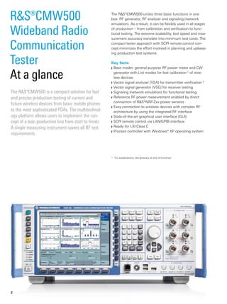
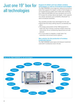
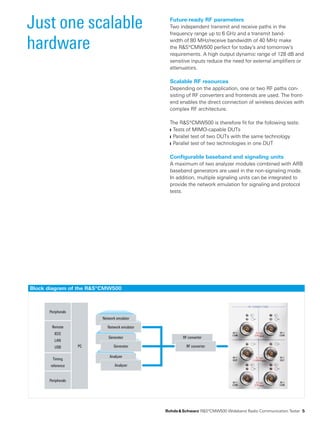
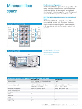
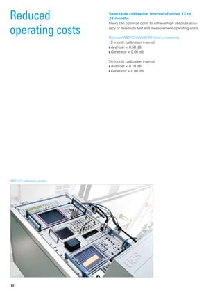
SlideShare a Scribd company logo

Test & Measurement
ProductBrochure|05.00
R&S®CMW500
­Wideband Radio
Communication­Tester
RF ­production testing
The R&S®CMW500 unites three basic functions in one
box: RF generator, RF analyzer and signaling (network
emulation). As a result, it can be flexibly used in all stages
of production – from calibration and verification to func-
tional testing. The extreme scalability, test speed and mea-
surement accuracy translate into minimum test costs. The
compact tester approach with SCPI remote control con-
cept minimizes the effort involved in planning and upkeep-
ing production test systems.
Key facts
Base model: general-purpose RF power meter and CW❙❙
generator with List modes for fast calibration 1)
of wire-
less devices
Vector signal analyzer (VSA) for transmitter verification ❙❙ 1)
Vector signal generator (VSG) for receiver testing❙❙
Signaling (network emulation) for functional testing❙❙
Reference RF power measurement enabled by direct❙❙
­connection of R&S®NRP-Zxx power sensors
Easy connection to wireless devices with complex RF❙❙
­architecture by using the integrated RF interface
State-of-the-art graphical user interface (GUI)❙❙
SCPI remote control via LAN/GPIB interface❙❙
Ready for LXI Class C❙❙
Process controller with Windows® XP operating ­system❙❙
The R&S®CMW500 is a compact solution for fast
and precise production testing of current and
­future wireless devices from basic mobile phones
to the most sophisticated PDAs. The multitechnol-
ogy platform allows users to implement the con-
cept of a lean production line from start to finish:
A single measuring instrument covers all RF test
­requirements.
R&S®CMW500
Wideband Radio
Communication­
­Tester
At a glance
1)
	 For explanations, see glossary at end of brochure.
2
R&S®CMW500
Wideband Radio
Communication­
­Tester
Benefits and
key features
Just one 19" box for all technologies
Support of cellular and non-cellular wireless technologies❙❙
as well as of broadcast technologies
Slim solution for the production of wireless multimode❙❙
devices
page 4▷▷
Just one scalable hardware
Future-ready RF parameters❙❙
Scalable RF resources❙❙
Configurable baseband and signaling units❙❙
page 5▷▷
Drastically reduced test costs; alignment up to ten
times faster
R&S®Multi-Evaluation transmitter measurements❙❙
R&S®Smart Alignment ❙❙ 1)
concept
page 6▷▷
Optimized handling for production test systems
Minimum user risk owing to all-in-one architecture❙❙
Comprehensive RF frontend eliminating the need for❙❙
­external ­hardware
Optimum handling through Press & Go applications❙❙
page 8▷▷
Designed for high first pass yield
High absolute accuracy plus repeatability and linearity❙❙
Precise reference measurements by connecting❙❙
R&S®NRP-Zxx power sensors
page 10▷▷
Minimum floor space
Dual tester configuration❙❙
R&S®CMW280 wideband radio communication tester❙❙
page 11▷▷
Reduced operating costs
Selectable ­calibration interval of 12 or 24 months❙❙
page 12▷▷
Just one reliable T&M partner
Rohde & Schwarz actively participates in the evolution of❙❙
wireless communications standards
Rohde & Schwarz offers optional services to increase the❙❙
value of the R&S®CMW500
Rohde & Schwarz is the leading manufacturer of T & M❙❙
equipment for wireless standards and provides a
­complete test portfolio from a single source
Worldwide sales, application and service network❙❙
page 13▷▷
"WiMAX Forum" is a registered trademark of the WiMAX Forum. “WiMAX,“ the
WiMAX Forum logo, “WiMAX Forum Certified,“ and the WiMAX Forum Certified
logo are trademarks of the WiMAX Forum.
CDMA2000® is a registered trademark of the Telecommunications Industry
­Association (TIA - USA).
The Bluetooth® word mark and logos are registered trademarks owned by
­Bluetooth SIG, Inc. and any use of such marks by Rohde & Schwarz is under license.
	 Rohde & Schwarz R&S®CMW500 ­Wideband Radio Communication­Tester 3
Just one 19" box for
all technologies
Support of cellular and non-cellular wireless
­technologies as well as of broadcast technologies
The R&S®CMW500 is the single-box radiocommunications
tester that supports the largest number of technologies. It
can handle both the widely used mobile radio standards
(e.g. GSM and WCDMA) and new standards such as LTE.
To increase the wireless device test depth, it also supports
non-cellular standards such as WLAN or Bluetooth® as
well as broadcast standards.
This versatility provides many advantages for the user:
Multimode test setup cabling requires considerably less❙❙
effort
The energy consumption of the T & M equipment is❙❙
­lower than that of setups involving multiple measuring
­instruments; the air conditioning requirements are also
­reduced
It is much easier to integrate a single tester into❙❙
­automation and remote control systems
Slim solution for the production of wireless
­multimode devices
The R&S®CMW500 saves space and reduces investment
costs both in production and in the lab.
Use of the R&S®CMW500 for all technologies
Mobile WiMAX™
LTE FDD/TDD
CDMA2000® 1xRTT
CDMA2000® 1xEV-DO
WCDMA/HSPA
HSPA+
GSM
GPRS
EDGEEDGE Evolution
GPS
Bluetooth®
WLAN a/b/g/n
DVB-T
T-DMB
MediaFLO™
CMMB
FM stereo
TD-SCDMA
4
Block diagram of the R&S®CMW500
Generator
Generator
Analyzer
Analyzer
Network emulator
Network emulatorRemote
IEEE
LAN
USB
Timing
reference
Peripherals
Peripherals
PC
RF converter
RF converter
Future-ready RF parameters
Two independent transmit and receive paths in the
frequency range up to 6 GHz and a transmit band-
width of 80 MHz/receive bandwidth of 40 MHz make
the R&S®CMW500 perfect for today's and tomorrow's
­requirements. A high output ­dynamic range of 128 dB and
sensitive inputs reduce the need for external amplifiers or
­attenuators.
Scalable RF resources
Depending on the application, one or two RF paths con-
sisting of RF converters and frontends are used. The front­
end enables the direct connection of wireless devices with
complex RF architecture.
The R&S®CMW500 is therefore fit for the following tests:
Tests of MIMO-capable DUTs❙❙
Parallel test of two DUTs with the same technology❙❙
Parallel test of two technologies in one DUT❙❙
Configurable baseband and signaling units
A maximum of two analyzer modules combined with ARB
baseband generators are used in the non-signaling mode.
In addition, multiple signaling units can be integrated to
provide the network emulation for signaling and protocol
tests.
	 Rohde & Schwarz R&S®CMW500 ­Wideband Radio Communication­Tester 5
Just one scalable
hardware
Drastically
­reduced test costs;
­alignment up to ten
times faster
Ongoing technological innovation and the ever-rising
number of bands that must be supported increase the
complexity of state-of-the-art wireless devices. The test
effort multiplies, and the production costs rise. For these
reasons, finding new, time-saving alignment ­approaches
is essential. Rohde & Schwarz offers a significant reduc-
tion of test times compared to conventional methods
by means of R&S®Multi‑Evaluation 1)
TX measurements
and its R&S®Smart Alignment 1)
non-signaling concept.
The R&S®CMW500 all-in-one ­architecture 1)
with built‑in­
­analyzer and generator provides the fastest possible
­transmit-receive interaction and is the optimum solution
for time-critical tests in ­production.
R&S®Multi‑Evaluation: LTE TX measurement.
6
R&S®Multi-Evaluation transmitter measurements
Different evaluations (power, time mask, modulation❙❙
quality­, spectrum, code domain) can use an identical
­sampling data set
Time-overlapped data capturing and evaluation❙❙
Enhanced speed by switching off evaluations that are not❙❙
required
This approach not only ­increases the test speed in com-
parison with purely ­sequential data capturing and evalu-
ation but also ­ensures greater test depth. This results in a
more ­detailed overview of the transmitter functions, since
all measured parameters are correlated.
R&S®Smart Alignment concept
Fully automatic frequency and level switching with❙❙
­general-purpose RF generator and power meter in
List mode
R&S®Multi-Evaluation List mode ❙❙ 1)
helps ensure fast
­transmitter verification
Simultaneous transmitter and receiver alignment, if❙❙
­supported by the DUT 1)
Extensive trigger functions for analyzer/generator❙❙
Statistical evaluation included❙❙
Preconfigured identical test sequences in the DUT 1)
and
the tester minimize the volume of communications inside
the test system, which is the bottleneck of conventional
­approaches. Flexible R&S®CMW500 parameterization
­facilitates adaptation to the test philosophy of the wire-
less device under test and speeds up transfer to mass
­production.
	 Rohde & Schwarz R&S®CMW500 ­Wideband Radio Communication­Tester 7
The comprehensive RF ­frontend
­eliminates the need for ­external
­hardware (dual-tester front panel).
Optimized handling
for production test
systems
The R&S®CMW500 is a turnkey solution that can start test-
ing immediately after delivery. The fully integrated tester
with calibrated RF paths and Press & Go 1)
applications sim-
plifies generating and updating test sequences and pro-
duction test systems. The all‑in‑one architecture 1)
ensures
maximum test performance plus minimum footprint and
optimum power consumption. This concept for minimiz-
ing test costs comes from a company that has been suc-
cessfully supplying solutions for the production of wire­less
­devices for more than 30 years: Rohde & Schwarz.
Minimum user risk owing to all-in-one
­architecture
Built-in vector signal analyzer and generator as well as❙❙
signaling­
SCPI remote control via LAN or GPIB interface❙❙
Windows® XP operating system❙❙
Remote control via Windows® Remote Desktop❙❙
Connectors for mouse, keyboard and external monitor❙❙
Internal TCXO or OCXO timebase and 10 MHz reference❙❙
frequency output
External reference frequency (alternative)❙❙
Fully automatic RF path correction concept ❙❙ 1)
of
­frequency, temperature and level in realtime
Completely calibrated solution❙❙
Completely standard-conforming EMC ❙❙ 1)
characteristics
Matched power supply❙❙
The turnkey solution provides assured measurement
­accuracy without the user’s constant attention. Time- and
cost-intensive repetitive self-alignment ­procedures can be
omitted.
8
RF testing modes and product structure
Software options:
¸CMW-KGxxx
¸CMW-KWxxx
¸CMW-KVxxx
Hardware:
ARB + realtime
baseband generator
module
Generator
Software options:
¸CMW-KMxxx
Hardware:
baseband measure-
ment unit
Measurements
Software options:
¸CMW-KSxxx
Hardware:
signaling unit
Signaling
(network emulation)
Non-signaling mode
Signaling mode
Comprehensive RF frontend eliminating the need
for ­external ­hardware
Flexible RF interface for direct connection of wireless❙❙
devices­with complex RF architecture
Alternative: simultaneous connection of two wireless❙❙
­devices with one antenna each (connectors RF1 COM
and RF2 COM)
Entirely integrated into R&S®CMW500 path correction❙❙
concept 1)
Flexible path configuration via GUI ❙❙ 1)
Optimized for mass tests in production❙❙
Snap-N female connector RF1 OUT: RF output❙❙
Snap-N female connector RF1 COM:❙❙
combined RF input/output
Snap-N female connector RF2 COM:❙❙
combined RF input/output
The handling time for sequential testing of two wireless
devices­is reduced. The test system costs decrease while
­reliability and accuracy increase, since additional RF com-
ponents are not required.
Optimum handling through Press & Go ­applications
Highly automated measurements at the press of a button❙❙
Preconfigured in line with specifications of the selected❙❙
technology
Extensive statistical evaluations of measurement results❙❙
already implemented
Technology-specific measurement results are output;
no need to bother with time-consuming details such as
­calculation, limits, or statistics.
	 Rohde & Schwarz R&S®CMW500 ­Wideband Radio Communication­Tester 9
Test setup for reference measurements
with an R&S®NRP-Zxx ­power ­sensor and
an R&S®NGMO2 ­power supply.
Designed for high
first pass yield
High absolute accuracy plus repeatability and
­linearity
The R&S®CMW500 has been specially designed for
­production applications: Top priority was placed on
­accuracy, repeatability and linearity. These parameter have
a direct influence on the production yield. The higher the
accuracy of these parameters, the lower the number of
DUTs that are classified as faulty although they comply
with specifications. Internal temperature sensors auto-
matically adapt the measurement accuracy to the ambi-
ent ­conditions. It is not necessary to perform a calibra-
tion when temperatures vary or when the instrument is
­switched on.
Precise reference measurements by connecting
R&S®NRP‑Zxx power sensors
Highly accurate RF power measurements at any point in
the test setup make it possible to optimize test procedures
in production. It is possible to connect an R&S®NRP‑Zxx
power sensor directly to the R&S®CMW500 for reference
­measurements.
Relevant R&S®CMW500 RF power meter parameters
Level uncertainty < 0.50 dB, typ. < 0.30 dB
Level repeatability input level ≥ –40 dBm typ. < 0.01 dB
Level linearity with fixed expected nominal
power­ ­setting
level range 0 dB to –40 dB typ. < 0.15 dB
Relevant R&S®CMW500 generator parameters
Output level uncertainty output level > –120 dBm < 0.60 dB, typ. < 0.36 dB
Output level repeatability output level < –80 dBm typ. < 0.05 dB
Output level linearity with fixed RF output
­attenuator setting
output level range –130 dBm to –5 dBm,
GPRF generator List mode,
level range 0 dB to –30 dB
typ. < 0.15 dB
10
The R&S®CMW280 The R&S®CMW280 is the compact
version of the R&S®CMW500 and
has 20 % less depth.
Example of dual test setup
¸CMW500 (dual)
Analyzer 1
Generator 1
Analyzer 2
Generator 2
Mobile
phone
2
BT
GSM
WCDMA
DVB
Mobile
phone
1
BT
GSM
WCDMA
DVB
Minimum floor
space
Differences between the R&S®CMW500 and the R&S®CMW280
R&S®CMW500 R&S®CMW280
Testing capability 1 DUT, optionally 2 DUTs simultaneously in
­non-signaling mode
1 DUT
Dimensions (W × H × D) 465.1 mm × 197.3 mm × 517.0 mm
(18.3 in × 7.8 in × 20.4 in)
465.1 mm × 197.3 mm × 417.0 mm
(18.3 in × 7.8 in × 16.4 in)
Weight with typical options approx. 18 kg (approx. 40 lb) approx. 14 kg (approx. 31 lb)
Remote control interfaces
Front panel
LAN 1 –
Rear panel
LAN 1 1
IEEE 488 option option
USB type B 1 –
Dual tester configuration 1)
The R&S®CMW500 can optionally be configured as a dual
tester. This configuration includes dual test ­resources
so that two identical wireless devices can be tested
­simultaneously in the non-signaling mode. This approach
saves valuable floor space in the production hall.
R&S®CMW280 wideband radio communication
­tester
The R&S®CMW280 is the compact version of the
R&S®CMW500 and has 20 % less depth. The instru-
ment can be configured exclusively as a single tester
and ­requires only minimum floor space in classic test
­concepts.
	 Rohde & Schwarz R&S®CMW500 ­Wideband Radio Communication­Tester 11
R&S®UCS calibration system.­
Reduced
­operating costs
Selectable calibration interval of either 12 or
24 months
Users can optimize costs to achieve high absolute accu-
racy or minimum test and measurement operating costs.
Relevant R&S®CMW500 RF level uncertainty
12-month calibration interval:
Analyzer < 0.50 dB❙❙
Generator < 0.60 dB❙❙
24-month calibration interval:
Analyzer < 0.70 dB❙❙
Generator < 0.80 dB❙❙
12
Canada
USA
Mexico
Brazil
Colombia
Argentina
Uruguay
Chile
South Africa
United
Arab
Emirates
Saudi
Arabia India
Pakistan
Kazakhstan
Mongolei
Oman
China
Tanzania
Kenya
Ethiopia
Sudan
Egypt
Israel
Syria
Jordan
Iran
Senegal
Ghana
Nigeria
Algeria
Tunisia Japan
South
Korea
Malaysia
Indonesia
Australia
Singapore
New Zealand
Philippines
Taiwan
Thailand
Vietnam
Germany
Iceland
Dallas
Manaus
São Paulo
Portland Ottawa
New Delhi
Hyderabad
Bangalore
Shanghai
Shenzhen
Beijing
Hong Kong
Los Angeles
Baltimore/Washington
Munich
Cologne
United
Kingdom
Ukraine
Turkey
Switzerland
Sweden
Spain
Russian
Federation
Romania
Portugal
Poland
Norway
Netherlands
Italy
Hungary
Greece
Malta
France
Finland
Denmark
Czech RepublicBelgium
Austria
Milan
Hamburg
Cyprus
Azerbaijan
Slovakia
Belarus
Lithuania
Latvia
Estonia
Slovenia
Sales Level
Sales Locations
Service Level
Backup Service
Area Support Center
Local Service Center
Calibration and maintenance with standardized
automatic calibration systems available
Calibration and maintenance
Maintenance
Just one reliable
T & M partner
As the leading supplier of T & M equipment for wireless
­devices, Rohde & Schwarz is actively participating in 3GPP,
3GPP2 and OMA bodies to further develop the commu-
nications standards. Standardization results are imme-
diately implemented in the company's T & M equipment,
which incorporates decades of experience in wireless
­communications.
With its dense worldwide support and service net-
work, Rohde & Schwarz helps users to efficiently employ
the R&S®CMW500 and achieve maximum benefit and
­maximum ROI.
Rohde & Schwarz offers the following optional services:
Calibration and hardware maintenance❙❙
Extended warranty❙❙
Automatic software upgrade services❙❙
Fast, expert technical support by application engineers❙❙
User and technology training❙❙
Rohde & Schwarz offers the R&S®CMW500 radiocom-
munications tester and also additional T & M equipment
for wireless devices such as signal ­generators and signal
­analyzers. Hardware and software are optimally adapted to
each other because they come from a single source.
	 Rohde & Schwarz R&S®CMW500 ­Wideband Radio Communication­Tester 13
Application
Production test
on wireless
­devices with the
R&S®CMW500
Step 3: Functional testing of the assembled wireless
­device.
This is the only way to ensure that the specifications of
the relevant technology standard will be complied with
later during operation in the network and that the wireless
­device will operate reliably.
Irrespective of the preferred test concept, the
R&S®CMW500 can be used for all three production steps
as follows:
Calibration must be performed in the non-signaling mode
because the DUT has not yet been calibrated and signal-
ing procedures cannot yet be supported. At this stage,
the ­generator/analyzer functionality of the R&S®CMW500
comes into its own.
Depending on the chipset used, verification can be per-
formed in the non-signaling or in the signaling mode. The
following R&S®CMW500 functionalities are used for this
step:
Analyzer/generator (non-signaling mode)❙❙
Analyzer/network emulator (signaling mode)❙❙
Economically produced RF chips exhibit variations in
­frequency and level characteristics. The following test pro-
cedure must be applied during the production of wireless
devices:
Step 1: Calibration. Deviations from the ideal values for
transmitter and receiver must be measured, interpolated
and stored in correction tables.
Step 2: Verification of transmit and receive parameters.
Use of the R&S®CMW500 for cellular wireless technologies
Technology RF generator RF analyzer Network emulation (signaling)
LTE FDD ● ● ●
LTE TDD (TD-LTE) ● ● ●
Mobile WiMAX™ ● ● ●
CDMA2000® 1xRTT ● ● ●
CDMA2000® 1xEV-DO ● ● ●
TD-SCDMA ● ●
WCDMA/HSPA+ ● ● ●
GSM/GPRS/EDGE/EDGE Evolution ● ● ●
Use of the R&S®CMW500 for non-cellular wireless technologies
Technology RF generator RF analyzer
GPS ●
Bluetooth® ● ●
WLAN a/b/g/n ● ●
Use of the R&S®CMW500 for broadcast technologies
Technology RF generator RF analyzer
DVB-T ●
T-DMB ●
MediaFLO™ ●
CMMB ●
FM stereo radio ● ●
14
General-purpose RF power
­measurement menu.
During the functional test at the end of the production line,
the realtime behavior in the actual network is normally
checked. At this stage, the R&S®CMW500 in the signaling
mode is used as a network emulator.
Transmit power calibration
The R&S®CMW500 GPRF 1)
power measurement evaluates
a list of power steps at different levels and frequencies and
performs statistical evaluation. A wide range of IF filters is
available:
Gaussian filters, selectable bandwidths between❙❙
1 kHz and 10 MHz
Bandpass root-raised-cosine (RRC) filters, selectable❙❙
bandwidths between 1 kHz and 40 MHz, roll-off 0.1
WCDMA RRC filter (3GPP TS 34.121 specification),❙❙
3.84 MHz bandwidth, roll-off = 0.22
CDMA filter (TIA/EIA/IS-2000.2-A specification),❙❙
1.4 MHz bandwidth
Transmitter verification
The R&S®CMW500 offers the widest range of precise RF
measurements for wireless devices (R&S®CMW-KMxxx
options), including multiple different measurements of the
following parameters:
Power❙❙
Modulation quality❙❙
Spectrum❙❙
Code domain❙❙
The R&S®Multi-Evaluation approach enables different anal-
yses of the same data sample. The R&S®Multi-Evaluation
List mode (R&S®CMW-KM012 option) is a consistent
­implementation of the R&S®Smart Alignment concept
(­predefined test sequences) for transmitter verification.
Inner loop power control testing
The R&S®CMW500 is able to carry out this test in the
relevant technologies (R&S®CMW-KMxxx options). As
a prerequisite, the DUT must be stimulated using the
R&S®CMW500 generator or the signaling function.
	 Rohde & Schwarz R&S®CMW500 ­Wideband Radio Communication­Tester 15
General-purpose RF ­generator
­configuration menu.
Calibration of receiver signal strength
indication­ (RSSI) 1)
The R&S®CMW500 enables the following calibration
­scenario:
The GPRF 1)
generator in List mode can be operated with
preconfigured levels and frequencies. The precalculated
baseband signal, which is stored in the ARB 1)
memory,
can be provided with markers that stepwise switch the list
of the GPRF 1)
generator.
Multisegment waveforms and marker-triggered GPRF 1)
generator lists are prerequisites for minimum ARB 1)
setup
times and fast RSSI 1)
calibration scenarios.
Receiver verification in non-signaling mode
The receiver is checked for technology-specific absolute
sensitivity and maximum input level.
This verification is based on a BER test 1)
with the
R&S®CMW500 being used as the signal source.
The ARB + realtime 1)
baseband generator module
(R&S®CMW‑B110A option) provides technology-specific
signals with pilot and data channels. Depending on the
applicable test requirements, the following solutions are
offered:
ARB mode ❙❙ 1)
based on precalculated R&S®WinIQSIM2™
waveforms (R&S®CMW-KWxxx options) or customer-
specific waveforms
Online mode ❙❙ 1)
for pilot channels and PRBS user data
channels with high data volume (R&S®CMW-KGxxx
­options)
In single-ended BER testing 1)
, the bit error ratio is
­evaluated in the DUT or the DUT controller.
In loop BER testing 1)
, the data stream to be tested is
­routed back to the tester via the uplink. The R&S®CMW500
(R&S®CMW-KMxxx options are required) evaluates the bit
error ratio of the following ­channels via postprocessing:
GSM loop C❙❙
WCDMA RMC 12.2 kbps❙❙
TD-SCDMA RMC 12.2 kbps❙❙
16
WCDMA signaling menu.
Receiver verification in signaling mode
Non-acknowledged mode: This verification is performed
on a loop BER test 1)
with the R&S®CMW500 being used
as a signal source and realtime data analyzer. The device
under test (DUT) loops back the data stream to be tested.
Acknowledged mode: The R&S®CMW500 sends the data
stream to the receiver of the DUT. The DUT assesses
­reception quality and returns ACK/NACKs to the tester.
The tester compares the data packets sent with the ACK/
NACKs received and calculates the data block error ratio
(DBLER).
Functional test with easy callbox operation
The listed cellular technologies can be executed with auto­
matic protocol stacks to realistically emulate a network 2)
(signaling mode):
GSM/GRPS/EDGE❙❙
WCDMA❙❙
LTE FDD❙❙
CDMA2000® 1xRTT❙❙
CDMA2000® 1xEV-DO❙❙
Mobile WiMAX™❙❙
Depending on the technology used, the following proce-
dures are performed:
Registration❙❙
Call setup (voice, data)❙❙
All signaling parameters are automatically selected by the
R&S®CMW500, but the user can modify many of them.
­Local or remote operation and configuration of the net-
work ­emulation are performed interactively via the user
­interface.
2)
	 Optional R&S®CMW-B2xxA and R&S®CMW300A signaling units in combination
with R&S®CMW-KSxxx signaling software options.
	 Rohde & Schwarz R&S®CMW500 ­Wideband Radio Communication­Tester 17
Time mask screen:
GSM/GPRS/EDGE/EDGE Evolution
TX measurement.
R&S®CMW-KM200 measurement personality 3)
Burst power❙❙
Time mask❙❙
I/Q origin offset/imbalance (8PSK modulation scheme)❙❙
Error vector magnitude (8PSK modulation scheme)❙❙
Magnitude error (8PSK modulation scheme)❙❙
Phase error❙❙
Frequency error (GMSK modulation scheme)❙❙
Spectrum due to modulation❙❙
Spectrum due to switching❙❙
TX measurements
3)
	 R&S®Multi-Evaluation List mode supported in combination with
R&S®CMW‑KM012 option.
GSM/GPRS/EDGE
18
EDGE Evolution/
EGRS2-A extensions
R&S®CMW-KM202 measurement personality
Enables measurements for 16QAM modulation schemes❙❙
Modulation analysis screen:
EDGE Evolution TX measurement.
	 Rohde & Schwarz R&S®CMW500 ­Wideband Radio Communication­Tester 19
Overview screen: ­
WCDMA TX ­measurement –
R&S®Multi‑Evaluation.
WCDMA
R&S®CMW-KM400 measurement personality 3)
UE power measurements can be applied to❙❙
OFF/max./min. power
Error vector magnitude❙❙
Magnitude error❙❙
Phase error❙❙
I/Q origin offset/imbalance❙❙
Frequency error❙❙
Phase discontinuity❙❙
Adjacent channel leakage ratio❙❙
Spectrum emission mask❙❙
Occupied bandwidth❙❙
Code domain power❙❙
Peak code domain error❙❙
Code domain error❙❙
Code domain power monitor­❙❙
Code domain error monitor­❙❙
20
HSPA ­extensions
R&S®CMW-KM401 measurement personality
Half-slot measurements❙❙
Modulation analysis of HSPA channels❙❙
Code domain power measurement of HSPA channels❙❙
Code domain error versus slot measurement of HSPA❙❙
channels
HS-DPCCH power control❙❙
Phase discontinuity❙❙
R&S®CMW-KM403 measurement personality
16QAM modulation analysis❙❙
Relative code domain error❙❙
HSPA+ ­extensions
Overview screen:
relative CDE vs. slot measure-
ment screen of 16QAM ­signal (two
4PAM channels in I and Q path).
	 Rohde & Schwarz R&S®CMW500 ­Wideband Radio Communication­Tester 21
Overview screen:
LTE FDD TX measurement –
R&S®Multi-Evaluation.
R&S®CMW-KM500 measurement personality
Transmit power❙❙
Peak power❙❙
Resource block power❙❙
Error vector magnitude❙❙
Magnitude error❙❙
Phase error❙❙
Frequency error❙❙
I/Q origin offset❙❙
I/Q constellation diagram❙❙
In-band emissions❙❙
Spectrum flatness❙❙
Adjacent channel leakage ratio❙❙
Occupied bandwidth❙❙
Spectrum emission mask❙❙
LTE FDD
22
Overview screen:
LTE TDD TX measurement –
R&S®Multi-Evaluation.
R&S®CMW-KM550 measurement personality
Transmit power❙❙
Peak power❙❙
Resource block power❙❙
Error vector magnitude❙❙
Magnitude error❙❙
Phase error❙❙
Frequency error❙❙
I/Q origin offset❙❙
I/Q constellation diagram❙❙
In-band emissions❙❙
Spectrum flatness❙❙
Adjacent channel leakage ratio❙❙
Occupied bandwidth❙❙
Spectrum emission mask❙❙
LTE TDD (TD-LTE)
	 Rohde & Schwarz R&S®CMW500 ­Wideband Radio Communication­Tester 23
Overview screen:
CDMA2000® 1xRTT
TX measurement –
R&S®Multi-Evaluation.
R&S®CMW-KM800 measurement personality
MS power❙❙
Error vector magnitude❙❙
Magnitude error❙❙
Phase error❙❙
Frequency error❙❙
Carrier feedthrough❙❙
I/Q imbalance❙❙
Waveform quality❙❙
Adjacent channel power❙❙
Code domain power❙❙
Code domain error power❙❙
CDMA2000® 1xRTT
24
Overview screen:
CDMA2000® 1xEV-DO
TX measurement –
R&S®Multi-Evaluation.
R&S®CMW-KM880 measurement personality
MS power❙❙
Error vector magnitude❙❙
Magnitude error❙❙
Phase error❙❙
Frequency error❙❙
Carrier feedthrough❙❙
I/Q imbalance❙❙
Waveform quality❙❙
Adjacent channel power❙❙
Code domain power❙❙
Code domain error power❙❙
CDMA2000® 1xEV-DO
(Rel. 0 & Rev. A & Rev. B)
	 Rohde & Schwarz R&S®CMW500 ­Wideband Radio Communication­Tester 25
Overview screen:
Mobile WiMAX™ TX measure-
ment – R&S®Multi-Evaluation
(R&S®CMW-KM701 option).
R&S®CMW-KM700 measurement personality
Burst power❙❙
Time mask❙❙
Crest factor❙❙
Subcarrier power❙❙
Center frequency error❙❙
Error vector magnitude (unmodulated)❙❙
I/Q offset/imbalance❙❙
Gain imbalance❙❙
Quadrature error❙❙
Sample clock error❙❙
Spectral flatness (neighbor)❙❙
Occupied bandwidth❙❙
Adjacent channel power❙❙
Spectrum emission mask❙❙
Mobile WiMAX™
26
Overview screen:
TD-SCDMA TX measurement –
R&S®Multi-Evaluation.
R&S®CMW-KM750 measurement personality
UE power❙❙
Transmit ON/OFF time mask❙❙
Error vector magnitude❙❙
Magnitude error❙❙
Phase error❙❙
Frequency error❙❙
I/Q origin offset❙❙
I/Q imbalance❙❙
Waveform quality❙❙
Adjacent channel leakage ratio❙❙
Spectrum emission mask❙❙
Occupied bandwidth❙❙
Code domain power❙❙
Code domain error power❙❙
Code domain monitor❙❙
TD-SCDMA
	 Rohde & Schwarz R&S®CMW500 ­Wideband Radio Communication­Tester 27
Bluetooth® TX measurement –
R&S®Multi-Evaluation.
R&S®CMW-KM610 measurement personality
Basic rate:
Nominal power❙❙
Frequency accuracy❙❙
Frequency drift and max. drift rate❙❙
Frequency deviation❙❙
Spectrum: 20 dB bandwidth❙❙
Spectrum: adjacent channel power❙❙
Enhanced data rate:
Nominal power (GFSK, DPSK)❙❙
Frequency stability ω❙❙ i
Frequency stability ω❙❙ 0 max.
Differential error vector magnitude❙❙
Phase difference graph❙❙
I/Q constellation diagram❙❙
Bluetooth®
28
WLAN TX measurement –
R&S®Multi-Evaluation.
R&S®CMW-KM650 measurement personality
Burst power❙❙
Center frequency error❙❙
Symbol clock error, chip clock error❙❙
Error vector magnitude❙❙
I/Q constellation diagram❙❙
Spectral flatness❙❙
Transmit spectrum mask❙❙
IEEE 802.11 a/b/g
(WLAN)
R&S®CMW-KM651 measurement personality 3)
Burst power❙❙
Error vector magnitude❙❙
Center frequency error❙❙
Symbol clock error❙❙
I/Q constellation diagram❙❙
Spectral flatness❙❙
Transmit spectrum mask❙❙
IEEE 802.11 n
extension­
	 Rohde & Schwarz R&S®CMW500 ­Wideband Radio Communication­Tester 29
Recommended ­extra
R&S®CMWrun
­sequencer
software tool
Straightforward display of signaling test
reports with R&S®CMWrun.
Highlights
Multitechnology solution❙❙
General-purpose applications (R&S®CMW-KT051 option)■■
GSM and WCDMA applications (R&S®CMW-KT053■■
­option)
LTE applications (R&S®CMW-KT055 option)■■
Mobile WiMAX™ applications (R&S®CMW‑KT057■■
­option)
CDMA2000® 1xRTT/1xEV-DO applications■■
(R&S®CMW‑KT058 option)
Ready-to-use solution, containing predefined❙❙
­Rohde & Schwarz applications for the technologies
­supported by the R&S®CMW500/R&S®CMW280
Application programming interface (API)-based engine❙❙
for easy and flexible integration of new applications
Ease of use due to dedicated interfaces for operation,❙❙
for editing sequences, for measurement reports and for
­debugging test sequences
Application for SCPI remote control via LAN or GPIB❙❙
­interface
The R&S®CMWrun sequencer software tool meets all
needs for executing test sequences to remote-control
the R&S®CMW500 in R & D, quality assurance and in the
­production of current and future wireless equipment.
The software engine is based on the execution of test
DLLs (plug-in assemblies). This architecture not only
­allows easy and straightforward configuration of test
­sequences without knowledge of specific remote
­programming of the instrument. It also provides full
­flexibility in configuring parameters and limits of the test
items provided in the R&S®CMWrun package options for
the ­different standards.
Ready-to-go solution with intuitive test plan
configuration for different ­technologies.
30
R&S®CMW500 specifications in brief
RF generator
Frequency range base model 70 MHz to 3300 MHz
with R&S®CMW-KB036 option 70 MHz to 6000 MHz
Output level range
RF1 COM, RF2 COM 100 MHz to 3300 MHz
continuous wave (CW) –130 dBm to –5 dBm
peak envelope power (PEP) up to –5 dBm
overranging (PEP) up to 0 dBm
RF1 OUT 100 MHz to 3300 MHz
continuous wave (CW) –120 dBm to +8 dBm
peak envelope power (PEP) up to +8 dBm
overranging (PEP) up to +13 dBm
Output level uncertainty in temperature range +20 °C to +35 °C, no overranging
RF1 COM, RF2 COM output level > –120 dBm
100 MHz to 3300 MHz < 0.6 dB
RF1 OUT output level > –110 dBm
100 MHz to 3300 MHz < 0.8 dB
Modulation source: arbitrary waveform generator (ARB) (R&S®CMW-B110A option)
Memory size   1024 Gbyte
Word length I 16 bit
Q 16 bit
marker 4 bit to 16 bit
Sample length with 4-bit marker up to 227.55 Msample
Sample rate minimum 400 Hz
maximum 100 MHz
RF power meter
Frequency range base model 70 MHz to 3300 MHz
with R&S®CMW-KB036 option 70 MHz to 6000 MHz
Expected nominal power setting range
RF1 COM, RF2 COM 100 MHz to 3300 MHz –47 dBm to +34 dBm
Level uncertainty in temperature range +20 °C to +35 °C
RF1 COM, RF2 COM 100 MHz to 3300 MHz < 0.5 dB
General data
Dimensions W × H × D 465.1 mm × 197.3 mm × 517.0 mm
(18.31 in × 7.77 in × 20.35 in)
(19" 1/1, 4 HU, 450)
Weight with typical options (single tester) approx. 18 kg
(approx. 39.68 lb)
Calibration interval 12 months recommended for highest accuracy,
see specified RF generator and RF analyzer level
uncertainty
24 months add 0.2 dB to specified RF generator and RF
­analyzer level uncertainty
	 Rohde & Schwarz R&S®CMW500 ­Wideband Radio Communication­Tester 31
Ordering information
Designation Type Order No. R&S®CMW500 R&S®
CMW280
Single (qty.) Dual (qty.) Single (qty.)
Model, mandatory
Wideband Radio Communication Tester R&S®CMW500 1201.0002K50 1 1 –
Wideband Radio Communication Tester R&S®CMW280 1201.0002K25 – – 1
Basic assembly, mandatory
R&S®CMW500 Wideband Radio Communication Tester,
Basic Assembly
R&S®CMW-PS502 1202.5408.02 1 1 –
R&S®CMW280 Wideband Radio Communication Tester,
Basic Assembly
R&S®CMW-PS280 1202.7300.02 – – 1
Selections, one out of two items to be selected, mandatory
Baseband Interconnection Board (fixed link) R&S®CMW-S550A 1202.4801.02 1 1 –
Baseband Interconnection Board (flexible link); alternatively,
­required for signaling
R&S®CMW-S550B 1202.4801.03 1 1 –
R&S®CMW500 Front Panel without Display/Keypad
(contains DVI interface )
R&S®CMW-S600A 1201.0102.02 1 1 –
R&S®CMW500 Front Panel with Display/Keypad, alternatively R&S®CMW-S600B 1201.0102.03 1 1 –
R&S®CMW280 Front Panel without Display/Keypad
(contains DVI interface )
R&S®CMW-S600E 1201.0102.06 – – 1
R&S®CMW280 Front Panel with Display/Keypad, alternatively R&S®CMW-S600F 1201.0102.07 – – 1
RF Frontend Module R&S®CMW-S590A 1202.5108.02 1 1 1
Hardware configuration, optional 
ARB + Realtime Baseband Generator Module R&S®CMW-B110A 1202.5508.02 1 2 1
Extra Baseband Measurement Unit R&S®CMW-B100A 1202.8607.02 – 1 –
Extra RF Converter Module (TRX) R&S®CMW-B570B 1202.8659.03 1 1 –
Extra RF Frontend Module R&S®CMW-B590A 1202.8707.02 1 1 –
IEEE Bus Interface Module (single connector) R&S®CMW-B612A 1202.5608.02 1 – 1
IEEE Bus Interface Module (dual connector), alternatively R&S®CMW-B612B 1202.5708.02 1 1 –
Digital Video Interface (DVI) Module
(only required for units with display/keypad)
R&S®CMW-B620A 1202.5808.02 1 1 1
OCXO Module R&S®CMW-B690A 1202.5908.02 1 1 1
OCXO Module (highly stable), alternatively R&S®CMW-B690B 1202.6004.02 1 1 1
Extended Frequency Range 3.3 GHz to 6 GHz
(per RF channel/TRX)
R&S®CMW-KB036 1203.0851.02 up to 2 2 1
Signaling configuration for WCDMA, LTE, optional
Signaling Unit, Wideband (SUW) R&S®CMW-B300A 1202.6304.02 1 – 1
Signaling (network emulation), WCDMA R&S®CMW-KS400 1204.0751.02 1 – 1
R&D Signaling Extension (network emulation) of
R&S®CMW‑KS400, WCDMA
R&S®CMW-KS410 1203.9807.02 1 – 1
Signaling (network emulation), LTE FDD R&S®CMW-KS500 1203.6108.02 1 – –
Signaling configuration for GSM/GPRS/EDGE, CDMA2000® 1xRTT, 1xEV-DO, Mobile WiMAX™ (one out of two to be selected: 1xEV-DO
or WiMAX™), optional
Signaling Unit, Universal (SUU) R&S®CMW-B200A 1202.6104.02 1 – 1
GSM/GPRS/EDGE Signaling Extension Module R&S®CMW-B210A 1202.6204.02 1 – 1
Signaling (network emulation), GSM/GPRS/EDGE R&S®CMW-KS200 1203.0600.02 1 – 1
CDMA Signaling Extension Module R&S®CMW-B220A 1202.7800.02 1 – –
Signaling (network emulation), CDMA2000® 1xRTT R&S®CMW-KS800 1203.3109.02 1 – –
1xEV-DO Signaling Extension Module R&S®CMW-B230A 1202.7600.02 1 – –
Signaling (network emulation), CDMA2000® 1xEV-DO R&S®CMW-KS880A 1203.3209.02 1 – –
WiMAX™ Signaling Extension Module R&S®CMW-B270A 1202.6504.02 1 – –
Signaling (BS emulation), WiMAX™ (IEEE 802.16e) R&S®CMW-KS700 1202.6704.02 1 – –
32
Designation Type Order No. R&S®CMW500 R&S®
CMW280
Single (qty.) Dual (qty.) Single (qty.)
TX measurement configuration, optional
FFT Spectrum Analyzer R&S®CMW-KM010 1203.5953.02 1 2 1
TX Measurement, I/Q versus Slot R&S®CMW-KM011 1203.0800.02 1 2 1
TX Measurement, R&S®Multi-Evaluation List Mode R&S®CMW-KM012 1203.4457.02 1 2 1
TX Measurement, GSM/GPRS/EDGE, Uplink R&S®CMW-KM200 1203.0551.02 1 2 1
TX Measurement, EDGE Evolution Extension of
R&S®CMW‑KM200, Uplink
R&S®CMW-KM201 1204.8404.02 1 2 1
TX Measurement, WCDMA, Uplink R&S®CMW-KM400 1203.0700.02 1 2 1
TX Measurement, WCDMA HSPA Extension of
R&S®CMW‑KM400, Uplink
R&S®CMW-KM401 1203.2954.02 1 2 1
TX Measurement, WCDMA HSPA+ Extension of
R&S®CMW‑KM401, ­Uplink
R&S®CMW-KM403 1203.9007.02 1 2 1
TX Measurement, LTE FDD, Uplink R&S®CMW-KM500 1203.5501.02 1 2 1
TX Measurement, LTE TDD (TD-LTE), Uplink R&S®CMW-KM550 1203.8952.02 1 2 1
TX Measurement, Bluetooth®, Basic Rate and EDR R&S®CMW-KM610 1203.6350.02 1 2 1
TX Measurement, FM Stereo Radio R&S®CMW-KM645 1204.8804.02 1 2 1
TX Measurement, WLAN (IEEE 802.11 a/b/g) R&S®CMW-KM650 1203.1658.02 1 2 1
TX Measurement, WLAN (IEEE 802.11 n) SISO Extension of
R&S®CMW-KM650
R&S®CMW-KM651 1203.9159.02 1 2 1
TX Measurement, Mobile WiMAX™ (IEEE 802.16 e) R&S®CMW-KM700 1202.6604.02 1 2 1
TX Measurement, Mobile WiMAX™ (IEEE 802.16 e),
R&D Extension of R&S®CMW-KM700
R&S®CMW-KM701 1202.6610.02 1 2 1
TX Measurement, TD-SCDMA, Uplink R&S®CMW-KM750 1203.2554.02 1 2 1
TX Measurement, CDMA2000® 1xRTT, Reverse Link R&S®CMW-KM800 1203.2602.02 1 2 1
TX Measurement, 1xEV-DO, Reverse Link R&S®CMW-KM880 1203.2854.02 1 2 1
Enable R&S®WinIQSIM2™ waveforms for ARB generator, optional
Enable R&S®WinIQSIM2™ Waveforms, AWGN R&S®CMW-KW010 1204.9000.02 1 2 1
Enable R&S®WinIQSIM2™ Waveforms, GSM/EDGE R&S®CMW-KW200 1203.0951.02 1 2 1
Enable R&S WinIQSIM2™ Waveforms, EDGE Evolution
­Extension of R&S®CMW-KW200
R&S®CMW-KW201 1204.8456.02 1 2 1
Enable R&S®WinIQSIM2™ Waveforms, WCDMA R&S®CMW-KW400 1203.1006.02 1 2 1
Enable R&S®WinIQSIM2™ Waveforms, WCDMA, HSDPA
­Extension of R&S®CMW-KG400
R&S®CMW-KW401 1203.1058.02 1 2 1
Enable R&S®WinIQSIM2™ Waveforms, WCDMA, HSUPA
­Extension of R&S®CMW-KG401
R&S®CMW-KW402 1203.1106.02 1 2 1
Enable R&S®WinIQSIM2™ Waveforms, WCDMA, HSPA+
­Extension of R&S®CMW-KW401 or R&S®CMW-KW402
R&S®CMW-KW403 1203.9059.02 1 2 1
Enable R&S®WinIQSIM2™ Waveforms, LTE FDD and
LTE TDD (TD-LTE)
R&S®CMW-KW500 1203.5553.02 1 2 1
Enable R&S®WinIQSIM2™ Waveforms, Bluetooth®,
Basic Rate and EDR
R&S®CMW-KW610 1203.6408.02 1 2 1
Enable R&S®WinIQSIM2™ Waveforms, GPS R&S®CMW-KW620 1203.6008.02 1 2 1
Enable R&S®WinIQSIM2™ Waveforms, DVB R&S®CMW-KW630 1203.6050.02 1 2 1
Enable R&S®WinIQSIM2™ Waveforms, WLAN
(IEEE 802.11 a/b/g)
R&S®CMW-KW650 1203.1258.02 1 2 1
Enable WinIQSIM2™ Waveforms, WLAN (IEEE 802.11 n)
­Extension of R&S®CMW-KW650
R&S®CMW-KW651 1203.9259.02 1 2 1
Enable R&S®WinIQSIM2™ Waveforms, WiMAX™ (IEEE 802.16) R&S®CMW-KW700 1203.1358.02 1 2 1
Enable R&S®WinIQSIM2™ Waveforms, TD-SCDMA R&S®CMW-KW750 1203.1406.02 1 2 1
Enable R&S®WinIQSIM2™ Waveforms,
TD-SCDMA Enhancements
R&S®CMW-KW751 1203.1458.02 1 2 1
Enable R&S®WinIQSIM2™ Waveforms, CDMA2000® 1xRTT R&S®CMW-KW800 1203.1506.02 1 2 1
Enable R&S®WinIQSIM2™ Waveforms, CDMA2000® 1xEV-DO R&S®CMW-KW880 1203.1558.02 1 2 1
	 Rohde & Schwarz R&S®CMW500 ­Wideband Radio Communication­Tester 33
Recommended extras and power sensors
Designation Type Order No.
LC TFT Display, 17", 1280 × 1024, DVI-D and Analog Interface R&S®PMC3 1082.6004.12
Keyboard with USB Interface (US character set) R&S®PSL-Z2 1157.6870.04
Mouse with USB Interface (optical, with wheel) R&S®PSL-Z10 1157.7060.04
19" Adapter, 4 HU, 1/1 for Design 2000 Cabinets R&S®ZZA-411 1096.3283.00
Average Power Sensor for Universal Use, 10 MHz to 18 GHz,
200 pW to 200 mW
R&S®NRP-Z21 1137.6000.02
Power Sensor Module, DC to 18 GHz R&S®NRP-Z27 1169.4102.02
Level Control Sensor, 10 MHz to 18 GHz, for Signal Generators R&S®NRP-Z28 1170.8008.02
Documentation of Calibration Values R&S®DCV-2 0240.2193.08
PC-based R&S®CMW applications for RF testing
Designation Type Order No.
Mandatory
USB Smartcard for PC-Based R&S®CMW Applications R&S®CMW-S089A 1202.7900.02
Optional
R&S®CMWrun Sequencer Software Tool, General Purpose R&S®CMW-KT051 1203.4157.02
R&S®CMWrun Sequencer Software Tool, GSM and WCDMA R&S®CMW-KT053 1204.8156.02
R&S®CMWrun Sequencer Software Tool, LTE R&S®CMW-KT055 1207.2107.02
R&S®CMWrun Sequencer Software Tool, WiMAX™ R&S®CMW-KT057 1203.4205.02
R&S®CMWrun Sequencer Software Tool,
CDMA2000® 1xRTT/1xEV-DO
R&S®CMW-KT058 1207.2159.02
Your local Rohde & Schwarz expert will help you determine the optimum solution for your requirements.
To find your nearest Rohde & Schwarz representative, visit
www.sales.rohde-schwarz.com
Designation Type Order No. R&S®CMW500 R&S®
CMW280
Single (qty.) Dual (qty.) Single (qty.)
Rohde & Schwarz waveform libraries for ARB generator, optional
Waveforms, T-DMB, I/Q Stream with Video/Audio Content R&S®CMW-KV634 1204.8004.02 1 2 1
Waveforms, MediaFLO™, I/Q Stream with Video/Audio ­Content R&S®CMW-KV636 1204.8056.02 1 2 1
Waveforms, CMMB, I/Q Stream with Video/Audio Content R&S®CMW-KV638 1204.8104.02 1 2 1
Waveforms, FM Stereo Radio R&S®CMW-KV645 1204.8956.02 1 2 1
Online generator configuration, optional
Generator, GSM/GPRS/EDGE, Downlink R&S®CMW-KG200 1203.0500.02 1 2 1
Generator, WCDMA, Downlink R&S®CMW-KG400 1203.0651.02 1 2 1
Generator, WCDMA HSPA Extension of R&S®CMW-KG400,
Downlink
R&S®CMW-KG401 1203.2902.02 1 2 1
Generator, CDMA2000® 1xRTT, Forward Link R&S®CMW-KG800 1203.3050.02 1 2 1
Sequencer software tool, optional
R&S®CMWrun Sequencer Software Tool, General Purpose R&S®CMW-KT051 1203.4157.02 1 2 1
R&S®CMWrun Sequencer Software Tool, GSM and WCDMA R&S®CMW-KT053 1204.8156.02 1 2 1
R&S®CMWrun Sequencer Software Tool, LTE R&S®CMW-KT055 1207.2107.02 1 2 1
R&S®CMWrun Sequencer Software Tool, WiMAX™ R&S®CMW-KT057 1203.4205.02 1 2 1
R&S®CMWrun Sequencer Software Tool,
CDMA2000® 1xRTT/1xEV-DO
R&S®CMW-KT058 1207.2159.02 1 2 1
34
Glossary
Term Explanation
ACLR Adjacent channel leakage ratio
ACP Adjacent channel power
Alignment Wireless device production cycle consisting of ­calibration and verification
All-in-one ­architecture Complete, highly integrated compact solution with ­assured measurement accuracy and optimum
­handling
ARB Generally used abbreviation for arbitrary waveform generator functionality
ARB generator mode Baseband generator mode where the modulation is implemented by means of precalculated
­waveforms stored in the ARB memory
ARB + realtime baseband generator module Generator module that supports not only the ­classic ARB mode but also the generation of complex
­modulated signals in realtime
BB Baseband
BER Bit error ratio
Calibration Wireless device production stage during which the transmit power steps and the RSSI steps are
­measured and compared to reference values. The correction factors obtained are stored in the
­wireless device. Other common designations: phasing, tuning, alignment
CW Continuous wave
DSP Digital signal processor
Dual tester Device configuration including two analyzers and two generators each for simultaneous testing of
two identical wireless devices
DUT Device under test
DVI Digital video interface
EMC Electromagnetic compatibility
EVM Error vector magnitude
GPRF General-purpose radio frequency
GPRF List mode Lists containing predefined levels and frequencies for GPRF generator/power meter test sequences
GUI Graphical user interface
HW Hardware
Loop BER test in non-signaling mode Method for RX verification in production. This test is performed in non-signaling mode, i.e. without
realtime network emulation. The bit error ratio is evaluated through postprocessing via the uplink
ME Magnitude error
MMI Man machine interface
OBW Occupied bandwidth
Online generator mode Baseband generator mode where complex modulated signals are generated in realtime; maximal
operation is performed via MMI
Path correction Method for increasing the measurement accuracy by taking into account the influence of frequency,
temperature and level on the RF attenuation of the measurement path
PE Phase error
PRBS Pseudo random bit sequence
Press & Go Turnkey, highly automated test functionality that is available at the press of a button
R&S®Multi-Evaluation Transmitter measurement concept where different measurement parameters use identical raw data
R&S®Smart Alignment Alignment concept where predefined identical test sequences in the DUT and in the tester reduce
the data volume in the test system and significantly shorten the test time
R&S®Multi-Evaluation List mode R&S®Smart Alignment method; fast TX verification based on predefined test sequences
RF Radio frequency
RMC Reference measurement channel
RSSI Receiver signal strength indication
RX Receiver
SEM Spectrum emission mask
Single-ended BER test Modern approach to receiver verification where the stimulating signal is provided by the measuring
instrument and the BER is calculated in the DUT
Single tester Device configuration for testing of a single wireless device
SW Software
Verification Wireless device production stage during which the most important transmit and receive parameters
are checked after calibration
VSA Vector signal analyzer
VSG Vector signal generator
	 Rohde & Schwarz R&S®CMW500 ­Wideband Radio Communication­Tester 35
R&S® is a registered trademark of Rohde & Schwarz GmbH & Co. KG
Trade names are trademarks of the owners | Printed in Germany (ch)
PD 5213.9211.12 | Version 05.00 | February 2010 | R&S®CMW500
Data without tolerance limits is not binding | Subject to change
© 2007 - 2010 Rohde & Schwarz GmbH Co. KG | 81671 München, Germany
About Rohde & Schwarz
Rohde & Schwarz is an independent group of companies
specializing in electronics. It is a leading supplier of solu-
tions in the fields of test and measurement, broadcast-
ing, radiomonitoring and radiolocation, as well as secure
communications. Established more than 75 years ago,
Rohde & Schwarz has a global presence and a dedicated
service network in over 70 countries. Company headquar-
ters are in Munich, Germany.
Environmental commitment
Energy-efficient products❙❙
Continuous improvement in environmental sustainability❙❙
ISO 14001-certified environmental management system❙❙
Certified Quality System
ISO 9001
Rohde & Schwarz GmbH & Co. KG
www.rohde-schwarz.com
Regional contact
Europe, Africa, Middle East❙❙
+49 89 4129 137 74
customersupport@rohde-schwarz.com
North America❙❙
1 888 TEST RSA (1 888 837 87 72)
customer.support@rsa.rohde-schwarz.com
Latin America❙❙
+1 410 910 79 88
customersupport.la@rohde-schwarz.com
Asia/Pacific❙❙
+65 65 13 04 88
customersupport.asia@rohde-schwarz.com
Service you can rely on
J	 Worldwide
J	 Local and personalized
J	 Customized and flexible
J	 Uncompromising quality
J	 Long-term dependability

More Related Content

What's hot

System(board level) noise figure analysis and optimization
System(board level) noise figure analysis and optimizationSystem(board level) noise figure analysis and optimization
System(board level) noise figure analysis and optimization
criterion123
 
IIP2 requirements in 4G LTE Handset Receivers
IIP2 requirements in 4G LTE Handset ReceiversIIP2 requirements in 4G LTE Handset Receivers
IIP2 requirements in 4G LTE Handset Receivers
criterion123
 
83092299 rru3804-overview
83092299 rru3804-overview83092299 rru3804-overview
83092299 rru3804-overview
Serik123
 
Carrier Aggregation Discussion
Carrier Aggregation DiscussionCarrier Aggregation Discussion
Carrier Aggregation Discussion
criterion123
 
Introduction to differential signal -For RF and EMC engineer
Introduction to differential signal -For RF and EMC engineerIntroduction to differential signal -For RF and EMC engineer
Introduction to differential signal -For RF and EMC engineer
criterion123
 
lte physical layer overview
 lte physical layer overview lte physical layer overview
lte physical layer overview
Praveen Kumar
 
Performance Requirement and Lessons Learnt of LTE Terminal_Transmitter Part
Performance Requirement and Lessons Learnt of LTE Terminal_Transmitter PartPerformance Requirement and Lessons Learnt of LTE Terminal_Transmitter Part
Performance Requirement and Lessons Learnt of LTE Terminal_Transmitter Part
criterion123
 
Challenges In Designing 5 GHz 802.11 ac WIFI Power Amplifiers
Challenges In Designing 5 GHz 802.11 ac WIFI Power AmplifiersChallenges In Designing 5 GHz 802.11 ac WIFI Power Amplifiers
Challenges In Designing 5 GHz 802.11 ac WIFI Power Amplifiers
criterion123
 
Interview question for 2g,3g,4g
Interview question for 2g,3g,4gInterview question for 2g,3g,4g
Interview question for 2g,3g,4g
Vijay Anand
 
3G drive test procedure (SSV) by Md Joynal Abaden
3G drive test procedure (SSV)  by Md Joynal Abaden3G drive test procedure (SSV)  by Md Joynal Abaden
3G drive test procedure (SSV) by Md Joynal Abaden
Md Joynal Abaden
 
Ericsson RBS 6000
Ericsson RBS 6000Ericsson RBS 6000
Ericsson RBS 6000
ibrahimnabil17
 
03 150323115803-conversion-gate01
03 150323115803-conversion-gate0103 150323115803-conversion-gate01
03 150323115803-conversion-gate01
Farhan Saeed
 
Performance requirement and lessons learnt of LTE terminal---transmitter part
Performance requirement and lessons learnt of LTE terminal---transmitter partPerformance requirement and lessons learnt of LTE terminal---transmitter part
Performance requirement and lessons learnt of LTE terminal---transmitter part
criterion123
 
A Study On TX Leakage In 4G LTE Handset Terminals
A Study On TX Leakage In 4G LTE Handset TerminalsA Study On TX Leakage In 4G LTE Handset Terminals
A Study On TX Leakage In 4G LTE Handset Terminals
criterion123
 
2-How to Extend DTAC LTE Coverage with Limited RRU Capacity.pdf
2-How to Extend DTAC LTE Coverage with Limited RRU Capacity.pdf2-How to Extend DTAC LTE Coverage with Limited RRU Capacity.pdf
2-How to Extend DTAC LTE Coverage with Limited RRU Capacity.pdf
ibrahim jerbi
 
Sensitivity or selectivity - How does eLNA impact the receriver performance
Sensitivity or selectivity  - How does eLNA impact the receriver performanceSensitivity or selectivity  - How does eLNA impact the receriver performance
Sensitivity or selectivity - How does eLNA impact the receriver performance
criterion123
 
One Case Study For GSM Unstable Output Power Issue
One Case Study For GSM Unstable Output  Power IssueOne Case Study For GSM Unstable Output  Power Issue
One Case Study For GSM Unstable Output Power Issue
criterion123
 
Rach procedure in lte
Rach procedure in lteRach procedure in lte
Rach procedure in lte
Saurav Banerjee
 
Lte mac presentation
Lte mac presentationLte mac presentation
Lte mac presentation
Praveen Kumar
 
Throughput calculation for LTE TDD and FDD systems
Throughput calculation for LTE TDD and FDD systemsThroughput calculation for LTE TDD and FDD systems
Throughput calculation for LTE TDD and FDD systems
Pei-Che Chang
 

What's hot (20)

System(board level) noise figure analysis and optimization
System(board level) noise figure analysis and optimizationSystem(board level) noise figure analysis and optimization
System(board level) noise figure analysis and optimization
 
IIP2 requirements in 4G LTE Handset Receivers
IIP2 requirements in 4G LTE Handset ReceiversIIP2 requirements in 4G LTE Handset Receivers
IIP2 requirements in 4G LTE Handset Receivers
 
83092299 rru3804-overview
83092299 rru3804-overview83092299 rru3804-overview
83092299 rru3804-overview
 
Carrier Aggregation Discussion
Carrier Aggregation DiscussionCarrier Aggregation Discussion
Carrier Aggregation Discussion
 
Introduction to differential signal -For RF and EMC engineer
Introduction to differential signal -For RF and EMC engineerIntroduction to differential signal -For RF and EMC engineer
Introduction to differential signal -For RF and EMC engineer
 
lte physical layer overview
 lte physical layer overview lte physical layer overview
lte physical layer overview
 
Performance Requirement and Lessons Learnt of LTE Terminal_Transmitter Part
Performance Requirement and Lessons Learnt of LTE Terminal_Transmitter PartPerformance Requirement and Lessons Learnt of LTE Terminal_Transmitter Part
Performance Requirement and Lessons Learnt of LTE Terminal_Transmitter Part
 
Challenges In Designing 5 GHz 802.11 ac WIFI Power Amplifiers
Challenges In Designing 5 GHz 802.11 ac WIFI Power AmplifiersChallenges In Designing 5 GHz 802.11 ac WIFI Power Amplifiers
Challenges In Designing 5 GHz 802.11 ac WIFI Power Amplifiers
 
Interview question for 2g,3g,4g
Interview question for 2g,3g,4gInterview question for 2g,3g,4g
Interview question for 2g,3g,4g
 
3G drive test procedure (SSV) by Md Joynal Abaden
3G drive test procedure (SSV)  by Md Joynal Abaden3G drive test procedure (SSV)  by Md Joynal Abaden
3G drive test procedure (SSV) by Md Joynal Abaden
 
Ericsson RBS 6000
Ericsson RBS 6000Ericsson RBS 6000
Ericsson RBS 6000
 
03 150323115803-conversion-gate01
03 150323115803-conversion-gate0103 150323115803-conversion-gate01
03 150323115803-conversion-gate01
 
Performance requirement and lessons learnt of LTE terminal---transmitter part
Performance requirement and lessons learnt of LTE terminal---transmitter partPerformance requirement and lessons learnt of LTE terminal---transmitter part
Performance requirement and lessons learnt of LTE terminal---transmitter part
 
A Study On TX Leakage In 4G LTE Handset Terminals
A Study On TX Leakage In 4G LTE Handset TerminalsA Study On TX Leakage In 4G LTE Handset Terminals
A Study On TX Leakage In 4G LTE Handset Terminals
 
2-How to Extend DTAC LTE Coverage with Limited RRU Capacity.pdf
2-How to Extend DTAC LTE Coverage with Limited RRU Capacity.pdf2-How to Extend DTAC LTE Coverage with Limited RRU Capacity.pdf
2-How to Extend DTAC LTE Coverage with Limited RRU Capacity.pdf
 
Sensitivity or selectivity - How does eLNA impact the receriver performance
Sensitivity or selectivity  - How does eLNA impact the receriver performanceSensitivity or selectivity  - How does eLNA impact the receriver performance
Sensitivity or selectivity - How does eLNA impact the receriver performance
 
One Case Study For GSM Unstable Output Power Issue
One Case Study For GSM Unstable Output  Power IssueOne Case Study For GSM Unstable Output  Power Issue
One Case Study For GSM Unstable Output Power Issue
 
Rach procedure in lte
Rach procedure in lteRach procedure in lte
Rach procedure in lte
 
Lte mac presentation
Lte mac presentationLte mac presentation
Lte mac presentation
 
Throughput calculation for LTE TDD and FDD systems
Throughput calculation for LTE TDD and FDD systemsThroughput calculation for LTE TDD and FDD systems
Throughput calculation for LTE TDD and FDD systems
 

Similar to Cmw500 bro en

STS Characterization to Production Test
STS Characterization to Production TestSTS Characterization to Production Test
STS Characterization to Production TestHank Lydick
 
Euro india2006 wirelessradioembeddedchallenges
Euro india2006 wirelessradioembeddedchallengesEuro india2006 wirelessradioembeddedchallenges
Euro india2006 wirelessradioembeddedchallengesArpan Pal
 
transforming-wireless-system-design-with-matlab-and-ni.pdf
transforming-wireless-system-design-with-matlab-and-ni.pdftransforming-wireless-system-design-with-matlab-and-ni.pdf
transforming-wireless-system-design-with-matlab-and-ni.pdf
JunaidKhan188662
 
STS RF IC Test System
STS RF IC Test SystemSTS RF IC Test System
STS RF IC Test SystemHank Lydick
 
VEGA Wireless Communication With PLICSRADIO - Technology Brochure
VEGA Wireless Communication With PLICSRADIO - Technology BrochureVEGA Wireless Communication With PLICSRADIO - Technology Brochure
VEGA Wireless Communication With PLICSRADIO - Technology BrochureThorne & Derrick UK
 
Fsl bro en_0758_2790_12_v0700
Fsl bro en_0758_2790_12_v0700Fsl bro en_0758_2790_12_v0700
Fsl bro en_0758_2790_12_v0700
Eric Wu
 
Sigfox Technology Overview (nov 2017)
Sigfox Technology Overview (nov 2017)Sigfox Technology Overview (nov 2017)
Sigfox Technology Overview (nov 2017)
Nicolas Lesconnec
 
Sigfox Technology Overview (nov 2017)
Sigfox Technology Overview (nov 2017)Sigfox Technology Overview (nov 2017)
Sigfox Technology Overview (nov 2017)
Nicolas Lesconnec
 
Making 5G New Radio a Reality - by Qualcomm
Making 5G New Radio a Reality - by QualcommMaking 5G New Radio a Reality - by Qualcomm
Making 5G New Radio a Reality - by Qualcomm
Aydin Karaer
 
Making 5G NR a reality
Making 5G NR a realityMaking 5G NR a reality
Making 5G NR a reality
Qualcomm Research
 
Tektronix keithley Product and Application update Q2 2016
Tektronix keithley Product and Application update Q2 2016Tektronix keithley Product and Application update Q2 2016
Tektronix keithley Product and Application update Q2 2016
Jeff Sable
 
Commercializing RF SOI
Commercializing RF SOI Commercializing RF SOI
Commercializing RF SOI
RFSOI
 
MaxEye SDR System Level Testing
MaxEye SDR System Level TestingMaxEye SDR System Level Testing
MaxEye SDR System Level Testing
MaxEye Technologies Private Limited
 
Electricot
ElectricotElectricot
Electricothobbis
 
Best EXFO OTDR in India at affordable Prices
Best EXFO OTDR in India at affordable PricesBest EXFO OTDR in India at affordable Prices
Best EXFO OTDR in India at affordable Prices
SPI Engineers
 
EXFO Maxtester 715B Single-mode Handheld OTDR – SPI Engineers
EXFO Maxtester 715B Single-mode Handheld OTDR – SPI EngineersEXFO Maxtester 715B Single-mode Handheld OTDR – SPI Engineers
EXFO Maxtester 715B Single-mode Handheld OTDR – SPI Engineers
SPI Engineers
 

Similar to Cmw500 bro en (20)

STS Characterization to Production Test
STS Characterization to Production TestSTS Characterization to Production Test
STS Characterization to Production Test
 
Euro india2006 wirelessradioembeddedchallenges
Euro india2006 wirelessradioembeddedchallengesEuro india2006 wirelessradioembeddedchallenges
Euro india2006 wirelessradioembeddedchallenges
 
transforming-wireless-system-design-with-matlab-and-ni.pdf
transforming-wireless-system-design-with-matlab-and-ni.pdftransforming-wireless-system-design-with-matlab-and-ni.pdf
transforming-wireless-system-design-with-matlab-and-ni.pdf
 
5989-3247EN
5989-3247EN5989-3247EN
5989-3247EN
 
STS RF IC Test System
STS RF IC Test SystemSTS RF IC Test System
STS RF IC Test System
 
VEGA Wireless Communication With PLICSRADIO - Technology Brochure
VEGA Wireless Communication With PLICSRADIO - Technology BrochureVEGA Wireless Communication With PLICSRADIO - Technology Brochure
VEGA Wireless Communication With PLICSRADIO - Technology Brochure
 
RS_insert
RS_insertRS_insert
RS_insert
 
Fsl bro en_0758_2790_12_v0700
Fsl bro en_0758_2790_12_v0700Fsl bro en_0758_2790_12_v0700
Fsl bro en_0758_2790_12_v0700
 
WCDMA_FAST_507-08
WCDMA_FAST_507-08WCDMA_FAST_507-08
WCDMA_FAST_507-08
 
Sigfox Technology Overview (nov 2017)
Sigfox Technology Overview (nov 2017)Sigfox Technology Overview (nov 2017)
Sigfox Technology Overview (nov 2017)
 
Sigfox Technology Overview (nov 2017)
Sigfox Technology Overview (nov 2017)Sigfox Technology Overview (nov 2017)
Sigfox Technology Overview (nov 2017)
 
Making 5G New Radio a Reality - by Qualcomm
Making 5G New Radio a Reality - by QualcommMaking 5G New Radio a Reality - by Qualcomm
Making 5G New Radio a Reality - by Qualcomm
 
Making 5G NR a reality
Making 5G NR a realityMaking 5G NR a reality
Making 5G NR a reality
 
Tektronix keithley Product and Application update Q2 2016
Tektronix keithley Product and Application update Q2 2016Tektronix keithley Product and Application update Q2 2016
Tektronix keithley Product and Application update Q2 2016
 
Commercializing RF SOI
Commercializing RF SOI Commercializing RF SOI
Commercializing RF SOI
 
MaxEye SDR System Level Testing
MaxEye SDR System Level TestingMaxEye SDR System Level Testing
MaxEye SDR System Level Testing
 
Electricot
ElectricotElectricot
Electricot
 
JuswantoWardojo
JuswantoWardojoJuswantoWardojo
JuswantoWardojo
 
Best EXFO OTDR in India at affordable Prices
Best EXFO OTDR in India at affordable PricesBest EXFO OTDR in India at affordable Prices
Best EXFO OTDR in India at affordable Prices
 
EXFO Maxtester 715B Single-mode Handheld OTDR – SPI Engineers
EXFO Maxtester 715B Single-mode Handheld OTDR – SPI EngineersEXFO Maxtester 715B Single-mode Handheld OTDR – SPI Engineers
EXFO Maxtester 715B Single-mode Handheld OTDR – SPI Engineers
 

Recently uploaded

SCHIZOPHRENIA Disorder/ Brain Disorder.pdf
SCHIZOPHRENIA Disorder/ Brain Disorder.pdfSCHIZOPHRENIA Disorder/ Brain Disorder.pdf
SCHIZOPHRENIA Disorder/ Brain Disorder.pdf
SELF-EXPLANATORY
 
Unveiling the Energy Potential of Marshmallow Deposits.pdf
Unveiling the Energy Potential of Marshmallow Deposits.pdfUnveiling the Energy Potential of Marshmallow Deposits.pdf
Unveiling the Energy Potential of Marshmallow Deposits.pdf
Erdal Coalmaker
 
platelets_clotting_biogenesis.clot retractionpptx
platelets_clotting_biogenesis.clot retractionpptxplatelets_clotting_biogenesis.clot retractionpptx
platelets_clotting_biogenesis.clot retractionpptx
muralinath2
 
erythropoiesis-I_mechanism& clinical significance.pptx
erythropoiesis-I_mechanism& clinical significance.pptxerythropoiesis-I_mechanism& clinical significance.pptx
erythropoiesis-I_mechanism& clinical significance.pptx
muralinath2
 
Lab report on liquid viscosity of glycerin
Lab report on liquid viscosity of glycerinLab report on liquid viscosity of glycerin
Lab report on liquid viscosity of glycerin
ossaicprecious19
 
THE IMPORTANCE OF MARTIAN ATMOSPHERE SAMPLE RETURN.
THE IMPORTANCE OF MARTIAN ATMOSPHERE SAMPLE RETURN.THE IMPORTANCE OF MARTIAN ATMOSPHERE SAMPLE RETURN.
THE IMPORTANCE OF MARTIAN ATMOSPHERE SAMPLE RETURN.
Sérgio Sacani
 
Citrus Greening Disease and its Management
Citrus Greening Disease and its ManagementCitrus Greening Disease and its Management
Citrus Greening Disease and its Management
subedisuryaofficial
 
In silico drugs analogue design: novobiocin analogues.pptx
In silico drugs analogue design: novobiocin analogues.pptxIn silico drugs analogue design: novobiocin analogues.pptx
In silico drugs analogue design: novobiocin analogues.pptx
AlaminAfendy1
 
ESR_factors_affect-clinic significance-Pathysiology.pptx
ESR_factors_affect-clinic significance-Pathysiology.pptxESR_factors_affect-clinic significance-Pathysiology.pptx
ESR_factors_affect-clinic significance-Pathysiology.pptx
muralinath2
 
Mammalian Pineal Body Structure and Also Functions
Mammalian Pineal Body Structure and Also FunctionsMammalian Pineal Body Structure and Also Functions
Mammalian Pineal Body Structure and Also Functions
YOGESH DOGRA
 
RNA INTERFERENCE: UNRAVELING GENETIC SILENCING
RNA INTERFERENCE: UNRAVELING GENETIC SILENCINGRNA INTERFERENCE: UNRAVELING GENETIC SILENCING
RNA INTERFERENCE: UNRAVELING GENETIC SILENCING
AADYARAJPANDEY1
 
EY - Supply Chain Services 2018_template.pptx
EY - Supply Chain Services 2018_template.pptxEY - Supply Chain Services 2018_template.pptx
EY - Supply Chain Services 2018_template.pptx
AlguinaldoKong
 
(May 29th, 2024) Advancements in Intravital Microscopy- Insights for Preclini...
(May 29th, 2024) Advancements in Intravital Microscopy- Insights for Preclini...(May 29th, 2024) Advancements in Intravital Microscopy- Insights for Preclini...
(May 29th, 2024) Advancements in Intravital Microscopy- Insights for Preclini...
Scintica Instrumentation
 
Astronomy Update- Curiosity’s exploration of Mars _ Local Briefs _ leadertele...
Astronomy Update- Curiosity’s exploration of Mars _ Local Briefs _ leadertele...Astronomy Update- Curiosity’s exploration of Mars _ Local Briefs _ leadertele...
Astronomy Update- Curiosity’s exploration of Mars _ Local Briefs _ leadertele...
NathanBaughman3
 
Hemostasis_importance& clinical significance.pptx
Hemostasis_importance& clinical significance.pptxHemostasis_importance& clinical significance.pptx
Hemostasis_importance& clinical significance.pptx
muralinath2
 
Structures and textures of metamorphic rocks
Structures and textures of metamorphic rocksStructures and textures of metamorphic rocks
Structures and textures of metamorphic rocks
kumarmathi863
 
The ASGCT Annual Meeting was packed with exciting progress in the field advan...
The ASGCT Annual Meeting was packed with exciting progress in the field advan...The ASGCT Annual Meeting was packed with exciting progress in the field advan...
The ASGCT Annual Meeting was packed with exciting progress in the field advan...
Health Advances
 
justice-and-fairness-ethics with example
justice-and-fairness-ethics with examplejustice-and-fairness-ethics with example
justice-and-fairness-ethics with example
azzyixes
 
Viksit bharat till 2047 India@2047.pptx
Viksit bharat till 2047  India@2047.pptxViksit bharat till 2047  India@2047.pptx
Viksit bharat till 2047 India@2047.pptx
rakeshsharma20142015
 
Orion Air Quality Monitoring Systems - CWS
Orion Air Quality Monitoring Systems - CWSOrion Air Quality Monitoring Systems - CWS
Orion Air Quality Monitoring Systems - CWS
Columbia Weather Systems
 

Recently uploaded (20)

SCHIZOPHRENIA Disorder/ Brain Disorder.pdf
SCHIZOPHRENIA Disorder/ Brain Disorder.pdfSCHIZOPHRENIA Disorder/ Brain Disorder.pdf
SCHIZOPHRENIA Disorder/ Brain Disorder.pdf
 
Unveiling the Energy Potential of Marshmallow Deposits.pdf
Unveiling the Energy Potential of Marshmallow Deposits.pdfUnveiling the Energy Potential of Marshmallow Deposits.pdf
Unveiling the Energy Potential of Marshmallow Deposits.pdf
 
platelets_clotting_biogenesis.clot retractionpptx
platelets_clotting_biogenesis.clot retractionpptxplatelets_clotting_biogenesis.clot retractionpptx
platelets_clotting_biogenesis.clot retractionpptx
 
erythropoiesis-I_mechanism& clinical significance.pptx
erythropoiesis-I_mechanism& clinical significance.pptxerythropoiesis-I_mechanism& clinical significance.pptx
erythropoiesis-I_mechanism& clinical significance.pptx
 
Lab report on liquid viscosity of glycerin
Lab report on liquid viscosity of glycerinLab report on liquid viscosity of glycerin
Lab report on liquid viscosity of glycerin
 
THE IMPORTANCE OF MARTIAN ATMOSPHERE SAMPLE RETURN.
THE IMPORTANCE OF MARTIAN ATMOSPHERE SAMPLE RETURN.THE IMPORTANCE OF MARTIAN ATMOSPHERE SAMPLE RETURN.
THE IMPORTANCE OF MARTIAN ATMOSPHERE SAMPLE RETURN.
 
Citrus Greening Disease and its Management
Citrus Greening Disease and its ManagementCitrus Greening Disease and its Management
Citrus Greening Disease and its Management
 
In silico drugs analogue design: novobiocin analogues.pptx
In silico drugs analogue design: novobiocin analogues.pptxIn silico drugs analogue design: novobiocin analogues.pptx
In silico drugs analogue design: novobiocin analogues.pptx
 
ESR_factors_affect-clinic significance-Pathysiology.pptx
ESR_factors_affect-clinic significance-Pathysiology.pptxESR_factors_affect-clinic significance-Pathysiology.pptx
ESR_factors_affect-clinic significance-Pathysiology.pptx
 
Mammalian Pineal Body Structure and Also Functions
Mammalian Pineal Body Structure and Also FunctionsMammalian Pineal Body Structure and Also Functions
Mammalian Pineal Body Structure and Also Functions
 
RNA INTERFERENCE: UNRAVELING GENETIC SILENCING
RNA INTERFERENCE: UNRAVELING GENETIC SILENCINGRNA INTERFERENCE: UNRAVELING GENETIC SILENCING
RNA INTERFERENCE: UNRAVELING GENETIC SILENCING
 
EY - Supply Chain Services 2018_template.pptx
EY - Supply Chain Services 2018_template.pptxEY - Supply Chain Services 2018_template.pptx
EY - Supply Chain Services 2018_template.pptx
 
(May 29th, 2024) Advancements in Intravital Microscopy- Insights for Preclini...
(May 29th, 2024) Advancements in Intravital Microscopy- Insights for Preclini...(May 29th, 2024) Advancements in Intravital Microscopy- Insights for Preclini...
(May 29th, 2024) Advancements in Intravital Microscopy- Insights for Preclini...
 
Astronomy Update- Curiosity’s exploration of Mars _ Local Briefs _ leadertele...
Astronomy Update- Curiosity’s exploration of Mars _ Local Briefs _ leadertele...Astronomy Update- Curiosity’s exploration of Mars _ Local Briefs _ leadertele...
Astronomy Update- Curiosity’s exploration of Mars _ Local Briefs _ leadertele...
 
Hemostasis_importance& clinical significance.pptx
Hemostasis_importance& clinical significance.pptxHemostasis_importance& clinical significance.pptx
Hemostasis_importance& clinical significance.pptx
 
Structures and textures of metamorphic rocks
Structures and textures of metamorphic rocksStructures and textures of metamorphic rocks
Structures and textures of metamorphic rocks
 
The ASGCT Annual Meeting was packed with exciting progress in the field advan...
The ASGCT Annual Meeting was packed with exciting progress in the field advan...The ASGCT Annual Meeting was packed with exciting progress in the field advan...
The ASGCT Annual Meeting was packed with exciting progress in the field advan...
 
justice-and-fairness-ethics with example
justice-and-fairness-ethics with examplejustice-and-fairness-ethics with example
justice-and-fairness-ethics with example
 
Viksit bharat till 2047 India@2047.pptx
Viksit bharat till 2047  India@2047.pptxViksit bharat till 2047  India@2047.pptx
Viksit bharat till 2047 India@2047.pptx
 
Orion Air Quality Monitoring Systems - CWS
Orion Air Quality Monitoring Systems - CWSOrion Air Quality Monitoring Systems - CWS
Orion Air Quality Monitoring Systems - CWS
 

Cmw500 bro en

  • 2. The R&S®CMW500 unites three basic functions in one box: RF generator, RF analyzer and signaling (network emulation). As a result, it can be flexibly used in all stages of production – from calibration and verification to func- tional testing. The extreme scalability, test speed and mea- surement accuracy translate into minimum test costs. The compact tester approach with SCPI remote control con- cept minimizes the effort involved in planning and upkeep- ing production test systems. Key facts Base model: general-purpose RF power meter and CW❙❙ generator with List modes for fast calibration 1) of wire- less devices Vector signal analyzer (VSA) for transmitter verification ❙❙ 1) Vector signal generator (VSG) for receiver testing❙❙ Signaling (network emulation) for functional testing❙❙ Reference RF power measurement enabled by direct❙❙ ­connection of R&S®NRP-Zxx power sensors Easy connection to wireless devices with complex RF❙❙ ­architecture by using the integrated RF interface State-of-the-art graphical user interface (GUI)❙❙ SCPI remote control via LAN/GPIB interface❙❙ Ready for LXI Class C❙❙ Process controller with Windows® XP operating ­system❙❙ The R&S®CMW500 is a compact solution for fast and precise production testing of current and ­future wireless devices from basic mobile phones to the most sophisticated PDAs. The multitechnol- ogy platform allows users to implement the con- cept of a lean production line from start to finish: A single measuring instrument covers all RF test ­requirements. R&S®CMW500 Wideband Radio Communication­ ­Tester At a glance 1) For explanations, see glossary at end of brochure. 2
  • 3. R&S®CMW500 Wideband Radio Communication­ ­Tester Benefits and key features Just one 19" box for all technologies Support of cellular and non-cellular wireless technologies❙❙ as well as of broadcast technologies Slim solution for the production of wireless multimode❙❙ devices page 4▷▷ Just one scalable hardware Future-ready RF parameters❙❙ Scalable RF resources❙❙ Configurable baseband and signaling units❙❙ page 5▷▷ Drastically reduced test costs; alignment up to ten times faster R&S®Multi-Evaluation transmitter measurements❙❙ R&S®Smart Alignment ❙❙ 1) concept page 6▷▷ Optimized handling for production test systems Minimum user risk owing to all-in-one architecture❙❙ Comprehensive RF frontend eliminating the need for❙❙ ­external ­hardware Optimum handling through Press & Go applications❙❙ page 8▷▷ Designed for high first pass yield High absolute accuracy plus repeatability and linearity❙❙ Precise reference measurements by connecting❙❙ R&S®NRP-Zxx power sensors page 10▷▷ Minimum floor space Dual tester configuration❙❙ R&S®CMW280 wideband radio communication tester❙❙ page 11▷▷ Reduced operating costs Selectable ­calibration interval of 12 or 24 months❙❙ page 12▷▷ Just one reliable T&M partner Rohde & Schwarz actively participates in the evolution of❙❙ wireless communications standards Rohde & Schwarz offers optional services to increase the❙❙ value of the R&S®CMW500 Rohde & Schwarz is the leading manufacturer of T & M❙❙ equipment for wireless standards and provides a ­complete test portfolio from a single source Worldwide sales, application and service network❙❙ page 13▷▷ "WiMAX Forum" is a registered trademark of the WiMAX Forum. “WiMAX,“ the WiMAX Forum logo, “WiMAX Forum Certified,“ and the WiMAX Forum Certified logo are trademarks of the WiMAX Forum. CDMA2000® is a registered trademark of the Telecommunications Industry ­Association (TIA - USA). The Bluetooth® word mark and logos are registered trademarks owned by ­Bluetooth SIG, Inc. and any use of such marks by Rohde & Schwarz is under license. Rohde & Schwarz R&S®CMW500 ­Wideband Radio Communication­Tester 3
  • 4. Just one 19" box for all technologies Support of cellular and non-cellular wireless ­technologies as well as of broadcast technologies The R&S®CMW500 is the single-box radiocommunications tester that supports the largest number of technologies. It can handle both the widely used mobile radio standards (e.g. GSM and WCDMA) and new standards such as LTE. To increase the wireless device test depth, it also supports non-cellular standards such as WLAN or Bluetooth® as well as broadcast standards. This versatility provides many advantages for the user: Multimode test setup cabling requires considerably less❙❙ effort The energy consumption of the T & M equipment is❙❙ ­lower than that of setups involving multiple measuring ­instruments; the air conditioning requirements are also ­reduced It is much easier to integrate a single tester into❙❙ ­automation and remote control systems Slim solution for the production of wireless ­multimode devices The R&S®CMW500 saves space and reduces investment costs both in production and in the lab. Use of the R&S®CMW500 for all technologies Mobile WiMAX™ LTE FDD/TDD CDMA2000® 1xRTT CDMA2000® 1xEV-DO WCDMA/HSPA HSPA+ GSM GPRS EDGEEDGE Evolution GPS Bluetooth® WLAN a/b/g/n DVB-T T-DMB MediaFLO™ CMMB FM stereo TD-SCDMA 4
  • 5. Block diagram of the R&S®CMW500 Generator Generator Analyzer Analyzer Network emulator Network emulatorRemote IEEE LAN USB Timing reference Peripherals Peripherals PC RF converter RF converter Future-ready RF parameters Two independent transmit and receive paths in the frequency range up to 6 GHz and a transmit band- width of 80 MHz/receive bandwidth of 40 MHz make the R&S®CMW500 perfect for today's and tomorrow's ­requirements. A high output ­dynamic range of 128 dB and sensitive inputs reduce the need for external amplifiers or ­attenuators. Scalable RF resources Depending on the application, one or two RF paths con- sisting of RF converters and frontends are used. The front­ end enables the direct connection of wireless devices with complex RF architecture. The R&S®CMW500 is therefore fit for the following tests: Tests of MIMO-capable DUTs❙❙ Parallel test of two DUTs with the same technology❙❙ Parallel test of two technologies in one DUT❙❙ Configurable baseband and signaling units A maximum of two analyzer modules combined with ARB baseband generators are used in the non-signaling mode. In addition, multiple signaling units can be integrated to provide the network emulation for signaling and protocol tests. Rohde & Schwarz R&S®CMW500 ­Wideband Radio Communication­Tester 5 Just one scalable hardware
  • 6. Drastically ­reduced test costs; ­alignment up to ten times faster Ongoing technological innovation and the ever-rising number of bands that must be supported increase the complexity of state-of-the-art wireless devices. The test effort multiplies, and the production costs rise. For these reasons, finding new, time-saving alignment ­approaches is essential. Rohde & Schwarz offers a significant reduc- tion of test times compared to conventional methods by means of R&S®Multi‑Evaluation 1) TX measurements and its R&S®Smart Alignment 1) non-signaling concept. The R&S®CMW500 all-in-one ­architecture 1) with built‑in­ ­analyzer and generator provides the fastest possible ­transmit-receive interaction and is the optimum solution for time-critical tests in ­production. R&S®Multi‑Evaluation: LTE TX measurement. 6
  • 7. R&S®Multi-Evaluation transmitter measurements Different evaluations (power, time mask, modulation❙❙ quality­, spectrum, code domain) can use an identical ­sampling data set Time-overlapped data capturing and evaluation❙❙ Enhanced speed by switching off evaluations that are not❙❙ required This approach not only ­increases the test speed in com- parison with purely ­sequential data capturing and evalu- ation but also ­ensures greater test depth. This results in a more ­detailed overview of the transmitter functions, since all measured parameters are correlated. R&S®Smart Alignment concept Fully automatic frequency and level switching with❙❙ ­general-purpose RF generator and power meter in List mode R&S®Multi-Evaluation List mode ❙❙ 1) helps ensure fast ­transmitter verification Simultaneous transmitter and receiver alignment, if❙❙ ­supported by the DUT 1) Extensive trigger functions for analyzer/generator❙❙ Statistical evaluation included❙❙ Preconfigured identical test sequences in the DUT 1) and the tester minimize the volume of communications inside the test system, which is the bottleneck of conventional ­approaches. Flexible R&S®CMW500 parameterization ­facilitates adaptation to the test philosophy of the wire- less device under test and speeds up transfer to mass ­production. Rohde & Schwarz R&S®CMW500 ­Wideband Radio Communication­Tester 7
  • 8. The comprehensive RF ­frontend ­eliminates the need for ­external ­hardware (dual-tester front panel). Optimized handling for production test systems The R&S®CMW500 is a turnkey solution that can start test- ing immediately after delivery. The fully integrated tester with calibrated RF paths and Press & Go 1) applications sim- plifies generating and updating test sequences and pro- duction test systems. The all‑in‑one architecture 1) ensures maximum test performance plus minimum footprint and optimum power consumption. This concept for minimiz- ing test costs comes from a company that has been suc- cessfully supplying solutions for the production of wire­less ­devices for more than 30 years: Rohde & Schwarz. Minimum user risk owing to all-in-one ­architecture Built-in vector signal analyzer and generator as well as❙❙ signaling­ SCPI remote control via LAN or GPIB interface❙❙ Windows® XP operating system❙❙ Remote control via Windows® Remote Desktop❙❙ Connectors for mouse, keyboard and external monitor❙❙ Internal TCXO or OCXO timebase and 10 MHz reference❙❙ frequency output External reference frequency (alternative)❙❙ Fully automatic RF path correction concept ❙❙ 1) of ­frequency, temperature and level in realtime Completely calibrated solution❙❙ Completely standard-conforming EMC ❙❙ 1) characteristics Matched power supply❙❙ The turnkey solution provides assured measurement ­accuracy without the user’s constant attention. Time- and cost-intensive repetitive self-alignment ­procedures can be omitted. 8
  • 9. RF testing modes and product structure Software options: ¸CMW-KGxxx ¸CMW-KWxxx ¸CMW-KVxxx Hardware: ARB + realtime baseband generator module Generator Software options: ¸CMW-KMxxx Hardware: baseband measure- ment unit Measurements Software options: ¸CMW-KSxxx Hardware: signaling unit Signaling (network emulation) Non-signaling mode Signaling mode Comprehensive RF frontend eliminating the need for ­external ­hardware Flexible RF interface for direct connection of wireless❙❙ devices­with complex RF architecture Alternative: simultaneous connection of two wireless❙❙ ­devices with one antenna each (connectors RF1 COM and RF2 COM) Entirely integrated into R&S®CMW500 path correction❙❙ concept 1) Flexible path configuration via GUI ❙❙ 1) Optimized for mass tests in production❙❙ Snap-N female connector RF1 OUT: RF output❙❙ Snap-N female connector RF1 COM:❙❙ combined RF input/output Snap-N female connector RF2 COM:❙❙ combined RF input/output The handling time for sequential testing of two wireless devices­is reduced. The test system costs decrease while ­reliability and accuracy increase, since additional RF com- ponents are not required. Optimum handling through Press & Go ­applications Highly automated measurements at the press of a button❙❙ Preconfigured in line with specifications of the selected❙❙ technology Extensive statistical evaluations of measurement results❙❙ already implemented Technology-specific measurement results are output; no need to bother with time-consuming details such as ­calculation, limits, or statistics. Rohde & Schwarz R&S®CMW500 ­Wideband Radio Communication­Tester 9
  • 10. Test setup for reference measurements with an R&S®NRP-Zxx ­power ­sensor and an R&S®NGMO2 ­power supply. Designed for high first pass yield High absolute accuracy plus repeatability and ­linearity The R&S®CMW500 has been specially designed for ­production applications: Top priority was placed on ­accuracy, repeatability and linearity. These parameter have a direct influence on the production yield. The higher the accuracy of these parameters, the lower the number of DUTs that are classified as faulty although they comply with specifications. Internal temperature sensors auto- matically adapt the measurement accuracy to the ambi- ent ­conditions. It is not necessary to perform a calibra- tion when temperatures vary or when the instrument is ­switched on. Precise reference measurements by connecting R&S®NRP‑Zxx power sensors Highly accurate RF power measurements at any point in the test setup make it possible to optimize test procedures in production. It is possible to connect an R&S®NRP‑Zxx power sensor directly to the R&S®CMW500 for reference ­measurements. Relevant R&S®CMW500 RF power meter parameters Level uncertainty < 0.50 dB, typ. < 0.30 dB Level repeatability input level ≥ –40 dBm typ. < 0.01 dB Level linearity with fixed expected nominal power­ ­setting level range 0 dB to –40 dB typ. < 0.15 dB Relevant R&S®CMW500 generator parameters Output level uncertainty output level > –120 dBm < 0.60 dB, typ. < 0.36 dB Output level repeatability output level < –80 dBm typ. < 0.05 dB Output level linearity with fixed RF output ­attenuator setting output level range –130 dBm to –5 dBm, GPRF generator List mode, level range 0 dB to –30 dB typ. < 0.15 dB 10
  • 11. The R&S®CMW280 The R&S®CMW280 is the compact version of the R&S®CMW500 and has 20 % less depth. Example of dual test setup ¸CMW500 (dual) Analyzer 1 Generator 1 Analyzer 2 Generator 2 Mobile phone 2 BT GSM WCDMA DVB Mobile phone 1 BT GSM WCDMA DVB Minimum floor space Differences between the R&S®CMW500 and the R&S®CMW280 R&S®CMW500 R&S®CMW280 Testing capability 1 DUT, optionally 2 DUTs simultaneously in ­non-signaling mode 1 DUT Dimensions (W × H × D) 465.1 mm × 197.3 mm × 517.0 mm (18.3 in × 7.8 in × 20.4 in) 465.1 mm × 197.3 mm × 417.0 mm (18.3 in × 7.8 in × 16.4 in) Weight with typical options approx. 18 kg (approx. 40 lb) approx. 14 kg (approx. 31 lb) Remote control interfaces Front panel LAN 1 – Rear panel LAN 1 1 IEEE 488 option option USB type B 1 – Dual tester configuration 1) The R&S®CMW500 can optionally be configured as a dual tester. This configuration includes dual test ­resources so that two identical wireless devices can be tested ­simultaneously in the non-signaling mode. This approach saves valuable floor space in the production hall. R&S®CMW280 wideband radio communication ­tester The R&S®CMW280 is the compact version of the R&S®CMW500 and has 20 % less depth. The instru- ment can be configured exclusively as a single tester and ­requires only minimum floor space in classic test ­concepts. Rohde & Schwarz R&S®CMW500 ­Wideband Radio Communication­Tester 11
  • 12. R&S®UCS calibration system.­ Reduced ­operating costs Selectable calibration interval of either 12 or 24 months Users can optimize costs to achieve high absolute accu- racy or minimum test and measurement operating costs. Relevant R&S®CMW500 RF level uncertainty 12-month calibration interval: Analyzer < 0.50 dB❙❙ Generator < 0.60 dB❙❙ 24-month calibration interval: Analyzer < 0.70 dB❙❙ Generator < 0.80 dB❙❙ 12
  • 13. Canada USA Mexico Brazil Colombia Argentina Uruguay Chile South Africa United Arab Emirates Saudi Arabia India Pakistan Kazakhstan Mongolei Oman China Tanzania Kenya Ethiopia Sudan Egypt Israel Syria Jordan Iran Senegal Ghana Nigeria Algeria Tunisia Japan South Korea Malaysia Indonesia Australia Singapore New Zealand Philippines Taiwan Thailand Vietnam Germany Iceland Dallas Manaus São Paulo Portland Ottawa New Delhi Hyderabad Bangalore Shanghai Shenzhen Beijing Hong Kong Los Angeles Baltimore/Washington Munich Cologne United Kingdom Ukraine Turkey Switzerland Sweden Spain Russian Federation Romania Portugal Poland Norway Netherlands Italy Hungary Greece Malta France Finland Denmark Czech RepublicBelgium Austria Milan Hamburg Cyprus Azerbaijan Slovakia Belarus Lithuania Latvia Estonia Slovenia Sales Level Sales Locations Service Level Backup Service Area Support Center Local Service Center Calibration and maintenance with standardized automatic calibration systems available Calibration and maintenance Maintenance Just one reliable T & M partner As the leading supplier of T & M equipment for wireless ­devices, Rohde & Schwarz is actively participating in 3GPP, 3GPP2 and OMA bodies to further develop the commu- nications standards. Standardization results are imme- diately implemented in the company's T & M equipment, which incorporates decades of experience in wireless ­communications. With its dense worldwide support and service net- work, Rohde & Schwarz helps users to efficiently employ the R&S®CMW500 and achieve maximum benefit and ­maximum ROI. Rohde & Schwarz offers the following optional services: Calibration and hardware maintenance❙❙ Extended warranty❙❙ Automatic software upgrade services❙❙ Fast, expert technical support by application engineers❙❙ User and technology training❙❙ Rohde & Schwarz offers the R&S®CMW500 radiocom- munications tester and also additional T & M equipment for wireless devices such as signal ­generators and signal ­analyzers. Hardware and software are optimally adapted to each other because they come from a single source. Rohde & Schwarz R&S®CMW500 ­Wideband Radio Communication­Tester 13
  • 14. Application Production test on wireless ­devices with the R&S®CMW500 Step 3: Functional testing of the assembled wireless ­device. This is the only way to ensure that the specifications of the relevant technology standard will be complied with later during operation in the network and that the wireless ­device will operate reliably. Irrespective of the preferred test concept, the R&S®CMW500 can be used for all three production steps as follows: Calibration must be performed in the non-signaling mode because the DUT has not yet been calibrated and signal- ing procedures cannot yet be supported. At this stage, the ­generator/analyzer functionality of the R&S®CMW500 comes into its own. Depending on the chipset used, verification can be per- formed in the non-signaling or in the signaling mode. The following R&S®CMW500 functionalities are used for this step: Analyzer/generator (non-signaling mode)❙❙ Analyzer/network emulator (signaling mode)❙❙ Economically produced RF chips exhibit variations in ­frequency and level characteristics. The following test pro- cedure must be applied during the production of wireless devices: Step 1: Calibration. Deviations from the ideal values for transmitter and receiver must be measured, interpolated and stored in correction tables. Step 2: Verification of transmit and receive parameters. Use of the R&S®CMW500 for cellular wireless technologies Technology RF generator RF analyzer Network emulation (signaling) LTE FDD ● ● ● LTE TDD (TD-LTE) ● ● ● Mobile WiMAX™ ● ● ● CDMA2000® 1xRTT ● ● ● CDMA2000® 1xEV-DO ● ● ● TD-SCDMA ● ● WCDMA/HSPA+ ● ● ● GSM/GPRS/EDGE/EDGE Evolution ● ● ● Use of the R&S®CMW500 for non-cellular wireless technologies Technology RF generator RF analyzer GPS ● Bluetooth® ● ● WLAN a/b/g/n ● ● Use of the R&S®CMW500 for broadcast technologies Technology RF generator RF analyzer DVB-T ● T-DMB ● MediaFLO™ ● CMMB ● FM stereo radio ● ● 14
  • 15. General-purpose RF power ­measurement menu. During the functional test at the end of the production line, the realtime behavior in the actual network is normally checked. At this stage, the R&S®CMW500 in the signaling mode is used as a network emulator. Transmit power calibration The R&S®CMW500 GPRF 1) power measurement evaluates a list of power steps at different levels and frequencies and performs statistical evaluation. A wide range of IF filters is available: Gaussian filters, selectable bandwidths between❙❙ 1 kHz and 10 MHz Bandpass root-raised-cosine (RRC) filters, selectable❙❙ bandwidths between 1 kHz and 40 MHz, roll-off 0.1 WCDMA RRC filter (3GPP TS 34.121 specification),❙❙ 3.84 MHz bandwidth, roll-off = 0.22 CDMA filter (TIA/EIA/IS-2000.2-A specification),❙❙ 1.4 MHz bandwidth Transmitter verification The R&S®CMW500 offers the widest range of precise RF measurements for wireless devices (R&S®CMW-KMxxx options), including multiple different measurements of the following parameters: Power❙❙ Modulation quality❙❙ Spectrum❙❙ Code domain❙❙ The R&S®Multi-Evaluation approach enables different anal- yses of the same data sample. The R&S®Multi-Evaluation List mode (R&S®CMW-KM012 option) is a consistent ­implementation of the R&S®Smart Alignment concept (­predefined test sequences) for transmitter verification. Inner loop power control testing The R&S®CMW500 is able to carry out this test in the relevant technologies (R&S®CMW-KMxxx options). As a prerequisite, the DUT must be stimulated using the R&S®CMW500 generator or the signaling function. Rohde & Schwarz R&S®CMW500 ­Wideband Radio Communication­Tester 15
  • 16. General-purpose RF ­generator ­configuration menu. Calibration of receiver signal strength indication­ (RSSI) 1) The R&S®CMW500 enables the following calibration ­scenario: The GPRF 1) generator in List mode can be operated with preconfigured levels and frequencies. The precalculated baseband signal, which is stored in the ARB 1) memory, can be provided with markers that stepwise switch the list of the GPRF 1) generator. Multisegment waveforms and marker-triggered GPRF 1) generator lists are prerequisites for minimum ARB 1) setup times and fast RSSI 1) calibration scenarios. Receiver verification in non-signaling mode The receiver is checked for technology-specific absolute sensitivity and maximum input level. This verification is based on a BER test 1) with the R&S®CMW500 being used as the signal source. The ARB + realtime 1) baseband generator module (R&S®CMW‑B110A option) provides technology-specific signals with pilot and data channels. Depending on the applicable test requirements, the following solutions are offered: ARB mode ❙❙ 1) based on precalculated R&S®WinIQSIM2™ waveforms (R&S®CMW-KWxxx options) or customer- specific waveforms Online mode ❙❙ 1) for pilot channels and PRBS user data channels with high data volume (R&S®CMW-KGxxx ­options) In single-ended BER testing 1) , the bit error ratio is ­evaluated in the DUT or the DUT controller. In loop BER testing 1) , the data stream to be tested is ­routed back to the tester via the uplink. The R&S®CMW500 (R&S®CMW-KMxxx options are required) evaluates the bit error ratio of the following ­channels via postprocessing: GSM loop C❙❙ WCDMA RMC 12.2 kbps❙❙ TD-SCDMA RMC 12.2 kbps❙❙ 16
  • 17. WCDMA signaling menu. Receiver verification in signaling mode Non-acknowledged mode: This verification is performed on a loop BER test 1) with the R&S®CMW500 being used as a signal source and realtime data analyzer. The device under test (DUT) loops back the data stream to be tested. Acknowledged mode: The R&S®CMW500 sends the data stream to the receiver of the DUT. The DUT assesses ­reception quality and returns ACK/NACKs to the tester. The tester compares the data packets sent with the ACK/ NACKs received and calculates the data block error ratio (DBLER). Functional test with easy callbox operation The listed cellular technologies can be executed with auto­ matic protocol stacks to realistically emulate a network 2) (signaling mode): GSM/GRPS/EDGE❙❙ WCDMA❙❙ LTE FDD❙❙ CDMA2000® 1xRTT❙❙ CDMA2000® 1xEV-DO❙❙ Mobile WiMAX™❙❙ Depending on the technology used, the following proce- dures are performed: Registration❙❙ Call setup (voice, data)❙❙ All signaling parameters are automatically selected by the R&S®CMW500, but the user can modify many of them. ­Local or remote operation and configuration of the net- work ­emulation are performed interactively via the user ­interface. 2) Optional R&S®CMW-B2xxA and R&S®CMW300A signaling units in combination with R&S®CMW-KSxxx signaling software options. Rohde & Schwarz R&S®CMW500 ­Wideband Radio Communication­Tester 17
  • 18. Time mask screen: GSM/GPRS/EDGE/EDGE Evolution TX measurement. R&S®CMW-KM200 measurement personality 3) Burst power❙❙ Time mask❙❙ I/Q origin offset/imbalance (8PSK modulation scheme)❙❙ Error vector magnitude (8PSK modulation scheme)❙❙ Magnitude error (8PSK modulation scheme)❙❙ Phase error❙❙ Frequency error (GMSK modulation scheme)❙❙ Spectrum due to modulation❙❙ Spectrum due to switching❙❙ TX measurements 3) R&S®Multi-Evaluation List mode supported in combination with R&S®CMW‑KM012 option. GSM/GPRS/EDGE 18
  • 19. EDGE Evolution/ EGRS2-A extensions R&S®CMW-KM202 measurement personality Enables measurements for 16QAM modulation schemes❙❙ Modulation analysis screen: EDGE Evolution TX measurement. Rohde & Schwarz R&S®CMW500 ­Wideband Radio Communication­Tester 19
  • 20. Overview screen: ­ WCDMA TX ­measurement – R&S®Multi‑Evaluation. WCDMA R&S®CMW-KM400 measurement personality 3) UE power measurements can be applied to❙❙ OFF/max./min. power Error vector magnitude❙❙ Magnitude error❙❙ Phase error❙❙ I/Q origin offset/imbalance❙❙ Frequency error❙❙ Phase discontinuity❙❙ Adjacent channel leakage ratio❙❙ Spectrum emission mask❙❙ Occupied bandwidth❙❙ Code domain power❙❙ Peak code domain error❙❙ Code domain error❙❙ Code domain power monitor­❙❙ Code domain error monitor­❙❙ 20
  • 21. HSPA ­extensions R&S®CMW-KM401 measurement personality Half-slot measurements❙❙ Modulation analysis of HSPA channels❙❙ Code domain power measurement of HSPA channels❙❙ Code domain error versus slot measurement of HSPA❙❙ channels HS-DPCCH power control❙❙ Phase discontinuity❙❙ R&S®CMW-KM403 measurement personality 16QAM modulation analysis❙❙ Relative code domain error❙❙ HSPA+ ­extensions Overview screen: relative CDE vs. slot measure- ment screen of 16QAM ­signal (two 4PAM channels in I and Q path). Rohde & Schwarz R&S®CMW500 ­Wideband Radio Communication­Tester 21
  • 22. Overview screen: LTE FDD TX measurement – R&S®Multi-Evaluation. R&S®CMW-KM500 measurement personality Transmit power❙❙ Peak power❙❙ Resource block power❙❙ Error vector magnitude❙❙ Magnitude error❙❙ Phase error❙❙ Frequency error❙❙ I/Q origin offset❙❙ I/Q constellation diagram❙❙ In-band emissions❙❙ Spectrum flatness❙❙ Adjacent channel leakage ratio❙❙ Occupied bandwidth❙❙ Spectrum emission mask❙❙ LTE FDD 22
  • 23. Overview screen: LTE TDD TX measurement – R&S®Multi-Evaluation. R&S®CMW-KM550 measurement personality Transmit power❙❙ Peak power❙❙ Resource block power❙❙ Error vector magnitude❙❙ Magnitude error❙❙ Phase error❙❙ Frequency error❙❙ I/Q origin offset❙❙ I/Q constellation diagram❙❙ In-band emissions❙❙ Spectrum flatness❙❙ Adjacent channel leakage ratio❙❙ Occupied bandwidth❙❙ Spectrum emission mask❙❙ LTE TDD (TD-LTE) Rohde & Schwarz R&S®CMW500 ­Wideband Radio Communication­Tester 23
  • 24. Overview screen: CDMA2000® 1xRTT TX measurement – R&S®Multi-Evaluation. R&S®CMW-KM800 measurement personality MS power❙❙ Error vector magnitude❙❙ Magnitude error❙❙ Phase error❙❙ Frequency error❙❙ Carrier feedthrough❙❙ I/Q imbalance❙❙ Waveform quality❙❙ Adjacent channel power❙❙ Code domain power❙❙ Code domain error power❙❙ CDMA2000® 1xRTT 24
  • 25. Overview screen: CDMA2000® 1xEV-DO TX measurement – R&S®Multi-Evaluation. R&S®CMW-KM880 measurement personality MS power❙❙ Error vector magnitude❙❙ Magnitude error❙❙ Phase error❙❙ Frequency error❙❙ Carrier feedthrough❙❙ I/Q imbalance❙❙ Waveform quality❙❙ Adjacent channel power❙❙ Code domain power❙❙ Code domain error power❙❙ CDMA2000® 1xEV-DO (Rel. 0 & Rev. A & Rev. B) Rohde & Schwarz R&S®CMW500 ­Wideband Radio Communication­Tester 25
  • 26. Overview screen: Mobile WiMAX™ TX measure- ment – R&S®Multi-Evaluation (R&S®CMW-KM701 option). R&S®CMW-KM700 measurement personality Burst power❙❙ Time mask❙❙ Crest factor❙❙ Subcarrier power❙❙ Center frequency error❙❙ Error vector magnitude (unmodulated)❙❙ I/Q offset/imbalance❙❙ Gain imbalance❙❙ Quadrature error❙❙ Sample clock error❙❙ Spectral flatness (neighbor)❙❙ Occupied bandwidth❙❙ Adjacent channel power❙❙ Spectrum emission mask❙❙ Mobile WiMAX™ 26
  • 27. Overview screen: TD-SCDMA TX measurement – R&S®Multi-Evaluation. R&S®CMW-KM750 measurement personality UE power❙❙ Transmit ON/OFF time mask❙❙ Error vector magnitude❙❙ Magnitude error❙❙ Phase error❙❙ Frequency error❙❙ I/Q origin offset❙❙ I/Q imbalance❙❙ Waveform quality❙❙ Adjacent channel leakage ratio❙❙ Spectrum emission mask❙❙ Occupied bandwidth❙❙ Code domain power❙❙ Code domain error power❙❙ Code domain monitor❙❙ TD-SCDMA Rohde & Schwarz R&S®CMW500 ­Wideband Radio Communication­Tester 27
  • 28. Bluetooth® TX measurement – R&S®Multi-Evaluation. R&S®CMW-KM610 measurement personality Basic rate: Nominal power❙❙ Frequency accuracy❙❙ Frequency drift and max. drift rate❙❙ Frequency deviation❙❙ Spectrum: 20 dB bandwidth❙❙ Spectrum: adjacent channel power❙❙ Enhanced data rate: Nominal power (GFSK, DPSK)❙❙ Frequency stability ω❙❙ i Frequency stability ω❙❙ 0 max. Differential error vector magnitude❙❙ Phase difference graph❙❙ I/Q constellation diagram❙❙ Bluetooth® 28
  • 29. WLAN TX measurement – R&S®Multi-Evaluation. R&S®CMW-KM650 measurement personality Burst power❙❙ Center frequency error❙❙ Symbol clock error, chip clock error❙❙ Error vector magnitude❙❙ I/Q constellation diagram❙❙ Spectral flatness❙❙ Transmit spectrum mask❙❙ IEEE 802.11 a/b/g (WLAN) R&S®CMW-KM651 measurement personality 3) Burst power❙❙ Error vector magnitude❙❙ Center frequency error❙❙ Symbol clock error❙❙ I/Q constellation diagram❙❙ Spectral flatness❙❙ Transmit spectrum mask❙❙ IEEE 802.11 n extension­ Rohde & Schwarz R&S®CMW500 ­Wideband Radio Communication­Tester 29
  • 30. Recommended ­extra R&S®CMWrun ­sequencer software tool Straightforward display of signaling test reports with R&S®CMWrun. Highlights Multitechnology solution❙❙ General-purpose applications (R&S®CMW-KT051 option)■■ GSM and WCDMA applications (R&S®CMW-KT053■■ ­option) LTE applications (R&S®CMW-KT055 option)■■ Mobile WiMAX™ applications (R&S®CMW‑KT057■■ ­option) CDMA2000® 1xRTT/1xEV-DO applications■■ (R&S®CMW‑KT058 option) Ready-to-use solution, containing predefined❙❙ ­Rohde & Schwarz applications for the technologies ­supported by the R&S®CMW500/R&S®CMW280 Application programming interface (API)-based engine❙❙ for easy and flexible integration of new applications Ease of use due to dedicated interfaces for operation,❙❙ for editing sequences, for measurement reports and for ­debugging test sequences Application for SCPI remote control via LAN or GPIB❙❙ ­interface The R&S®CMWrun sequencer software tool meets all needs for executing test sequences to remote-control the R&S®CMW500 in R & D, quality assurance and in the ­production of current and future wireless equipment. The software engine is based on the execution of test DLLs (plug-in assemblies). This architecture not only ­allows easy and straightforward configuration of test ­sequences without knowledge of specific remote ­programming of the instrument. It also provides full ­flexibility in configuring parameters and limits of the test items provided in the R&S®CMWrun package options for the ­different standards. Ready-to-go solution with intuitive test plan configuration for different ­technologies. 30
  • 31. R&S®CMW500 specifications in brief RF generator Frequency range base model 70 MHz to 3300 MHz with R&S®CMW-KB036 option 70 MHz to 6000 MHz Output level range RF1 COM, RF2 COM 100 MHz to 3300 MHz continuous wave (CW) –130 dBm to –5 dBm peak envelope power (PEP) up to –5 dBm overranging (PEP) up to 0 dBm RF1 OUT 100 MHz to 3300 MHz continuous wave (CW) –120 dBm to +8 dBm peak envelope power (PEP) up to +8 dBm overranging (PEP) up to +13 dBm Output level uncertainty in temperature range +20 °C to +35 °C, no overranging RF1 COM, RF2 COM output level > –120 dBm 100 MHz to 3300 MHz < 0.6 dB RF1 OUT output level > –110 dBm 100 MHz to 3300 MHz < 0.8 dB Modulation source: arbitrary waveform generator (ARB) (R&S®CMW-B110A option) Memory size   1024 Gbyte Word length I 16 bit Q 16 bit marker 4 bit to 16 bit Sample length with 4-bit marker up to 227.55 Msample Sample rate minimum 400 Hz maximum 100 MHz RF power meter Frequency range base model 70 MHz to 3300 MHz with R&S®CMW-KB036 option 70 MHz to 6000 MHz Expected nominal power setting range RF1 COM, RF2 COM 100 MHz to 3300 MHz –47 dBm to +34 dBm Level uncertainty in temperature range +20 °C to +35 °C RF1 COM, RF2 COM 100 MHz to 3300 MHz < 0.5 dB General data Dimensions W × H × D 465.1 mm × 197.3 mm × 517.0 mm (18.31 in × 7.77 in × 20.35 in) (19" 1/1, 4 HU, 450) Weight with typical options (single tester) approx. 18 kg (approx. 39.68 lb) Calibration interval 12 months recommended for highest accuracy, see specified RF generator and RF analyzer level uncertainty 24 months add 0.2 dB to specified RF generator and RF ­analyzer level uncertainty Rohde & Schwarz R&S®CMW500 ­Wideband Radio Communication­Tester 31
  • 32. Ordering information Designation Type Order No. R&S®CMW500 R&S® CMW280 Single (qty.) Dual (qty.) Single (qty.) Model, mandatory Wideband Radio Communication Tester R&S®CMW500 1201.0002K50 1 1 – Wideband Radio Communication Tester R&S®CMW280 1201.0002K25 – – 1 Basic assembly, mandatory R&S®CMW500 Wideband Radio Communication Tester, Basic Assembly R&S®CMW-PS502 1202.5408.02 1 1 – R&S®CMW280 Wideband Radio Communication Tester, Basic Assembly R&S®CMW-PS280 1202.7300.02 – – 1 Selections, one out of two items to be selected, mandatory Baseband Interconnection Board (fixed link) R&S®CMW-S550A 1202.4801.02 1 1 – Baseband Interconnection Board (flexible link); alternatively, ­required for signaling R&S®CMW-S550B 1202.4801.03 1 1 – R&S®CMW500 Front Panel without Display/Keypad (contains DVI interface ) R&S®CMW-S600A 1201.0102.02 1 1 – R&S®CMW500 Front Panel with Display/Keypad, alternatively R&S®CMW-S600B 1201.0102.03 1 1 – R&S®CMW280 Front Panel without Display/Keypad (contains DVI interface ) R&S®CMW-S600E 1201.0102.06 – – 1 R&S®CMW280 Front Panel with Display/Keypad, alternatively R&S®CMW-S600F 1201.0102.07 – – 1 RF Frontend Module R&S®CMW-S590A 1202.5108.02 1 1 1 Hardware configuration, optional  ARB + Realtime Baseband Generator Module R&S®CMW-B110A 1202.5508.02 1 2 1 Extra Baseband Measurement Unit R&S®CMW-B100A 1202.8607.02 – 1 – Extra RF Converter Module (TRX) R&S®CMW-B570B 1202.8659.03 1 1 – Extra RF Frontend Module R&S®CMW-B590A 1202.8707.02 1 1 – IEEE Bus Interface Module (single connector) R&S®CMW-B612A 1202.5608.02 1 – 1 IEEE Bus Interface Module (dual connector), alternatively R&S®CMW-B612B 1202.5708.02 1 1 – Digital Video Interface (DVI) Module (only required for units with display/keypad) R&S®CMW-B620A 1202.5808.02 1 1 1 OCXO Module R&S®CMW-B690A 1202.5908.02 1 1 1 OCXO Module (highly stable), alternatively R&S®CMW-B690B 1202.6004.02 1 1 1 Extended Frequency Range 3.3 GHz to 6 GHz (per RF channel/TRX) R&S®CMW-KB036 1203.0851.02 up to 2 2 1 Signaling configuration for WCDMA, LTE, optional Signaling Unit, Wideband (SUW) R&S®CMW-B300A 1202.6304.02 1 – 1 Signaling (network emulation), WCDMA R&S®CMW-KS400 1204.0751.02 1 – 1 R&D Signaling Extension (network emulation) of R&S®CMW‑KS400, WCDMA R&S®CMW-KS410 1203.9807.02 1 – 1 Signaling (network emulation), LTE FDD R&S®CMW-KS500 1203.6108.02 1 – – Signaling configuration for GSM/GPRS/EDGE, CDMA2000® 1xRTT, 1xEV-DO, Mobile WiMAX™ (one out of two to be selected: 1xEV-DO or WiMAX™), optional Signaling Unit, Universal (SUU) R&S®CMW-B200A 1202.6104.02 1 – 1 GSM/GPRS/EDGE Signaling Extension Module R&S®CMW-B210A 1202.6204.02 1 – 1 Signaling (network emulation), GSM/GPRS/EDGE R&S®CMW-KS200 1203.0600.02 1 – 1 CDMA Signaling Extension Module R&S®CMW-B220A 1202.7800.02 1 – – Signaling (network emulation), CDMA2000® 1xRTT R&S®CMW-KS800 1203.3109.02 1 – – 1xEV-DO Signaling Extension Module R&S®CMW-B230A 1202.7600.02 1 – – Signaling (network emulation), CDMA2000® 1xEV-DO R&S®CMW-KS880A 1203.3209.02 1 – – WiMAX™ Signaling Extension Module R&S®CMW-B270A 1202.6504.02 1 – – Signaling (BS emulation), WiMAX™ (IEEE 802.16e) R&S®CMW-KS700 1202.6704.02 1 – – 32
  • 33. Designation Type Order No. R&S®CMW500 R&S® CMW280 Single (qty.) Dual (qty.) Single (qty.) TX measurement configuration, optional FFT Spectrum Analyzer R&S®CMW-KM010 1203.5953.02 1 2 1 TX Measurement, I/Q versus Slot R&S®CMW-KM011 1203.0800.02 1 2 1 TX Measurement, R&S®Multi-Evaluation List Mode R&S®CMW-KM012 1203.4457.02 1 2 1 TX Measurement, GSM/GPRS/EDGE, Uplink R&S®CMW-KM200 1203.0551.02 1 2 1 TX Measurement, EDGE Evolution Extension of R&S®CMW‑KM200, Uplink R&S®CMW-KM201 1204.8404.02 1 2 1 TX Measurement, WCDMA, Uplink R&S®CMW-KM400 1203.0700.02 1 2 1 TX Measurement, WCDMA HSPA Extension of R&S®CMW‑KM400, Uplink R&S®CMW-KM401 1203.2954.02 1 2 1 TX Measurement, WCDMA HSPA+ Extension of R&S®CMW‑KM401, ­Uplink R&S®CMW-KM403 1203.9007.02 1 2 1 TX Measurement, LTE FDD, Uplink R&S®CMW-KM500 1203.5501.02 1 2 1 TX Measurement, LTE TDD (TD-LTE), Uplink R&S®CMW-KM550 1203.8952.02 1 2 1 TX Measurement, Bluetooth®, Basic Rate and EDR R&S®CMW-KM610 1203.6350.02 1 2 1 TX Measurement, FM Stereo Radio R&S®CMW-KM645 1204.8804.02 1 2 1 TX Measurement, WLAN (IEEE 802.11 a/b/g) R&S®CMW-KM650 1203.1658.02 1 2 1 TX Measurement, WLAN (IEEE 802.11 n) SISO Extension of R&S®CMW-KM650 R&S®CMW-KM651 1203.9159.02 1 2 1 TX Measurement, Mobile WiMAX™ (IEEE 802.16 e) R&S®CMW-KM700 1202.6604.02 1 2 1 TX Measurement, Mobile WiMAX™ (IEEE 802.16 e), R&D Extension of R&S®CMW-KM700 R&S®CMW-KM701 1202.6610.02 1 2 1 TX Measurement, TD-SCDMA, Uplink R&S®CMW-KM750 1203.2554.02 1 2 1 TX Measurement, CDMA2000® 1xRTT, Reverse Link R&S®CMW-KM800 1203.2602.02 1 2 1 TX Measurement, 1xEV-DO, Reverse Link R&S®CMW-KM880 1203.2854.02 1 2 1 Enable R&S®WinIQSIM2™ waveforms for ARB generator, optional Enable R&S®WinIQSIM2™ Waveforms, AWGN R&S®CMW-KW010 1204.9000.02 1 2 1 Enable R&S®WinIQSIM2™ Waveforms, GSM/EDGE R&S®CMW-KW200 1203.0951.02 1 2 1 Enable R&S WinIQSIM2™ Waveforms, EDGE Evolution ­Extension of R&S®CMW-KW200 R&S®CMW-KW201 1204.8456.02 1 2 1 Enable R&S®WinIQSIM2™ Waveforms, WCDMA R&S®CMW-KW400 1203.1006.02 1 2 1 Enable R&S®WinIQSIM2™ Waveforms, WCDMA, HSDPA ­Extension of R&S®CMW-KG400 R&S®CMW-KW401 1203.1058.02 1 2 1 Enable R&S®WinIQSIM2™ Waveforms, WCDMA, HSUPA ­Extension of R&S®CMW-KG401 R&S®CMW-KW402 1203.1106.02 1 2 1 Enable R&S®WinIQSIM2™ Waveforms, WCDMA, HSPA+ ­Extension of R&S®CMW-KW401 or R&S®CMW-KW402 R&S®CMW-KW403 1203.9059.02 1 2 1 Enable R&S®WinIQSIM2™ Waveforms, LTE FDD and LTE TDD (TD-LTE) R&S®CMW-KW500 1203.5553.02 1 2 1 Enable R&S®WinIQSIM2™ Waveforms, Bluetooth®, Basic Rate and EDR R&S®CMW-KW610 1203.6408.02 1 2 1 Enable R&S®WinIQSIM2™ Waveforms, GPS R&S®CMW-KW620 1203.6008.02 1 2 1 Enable R&S®WinIQSIM2™ Waveforms, DVB R&S®CMW-KW630 1203.6050.02 1 2 1 Enable R&S®WinIQSIM2™ Waveforms, WLAN (IEEE 802.11 a/b/g) R&S®CMW-KW650 1203.1258.02 1 2 1 Enable WinIQSIM2™ Waveforms, WLAN (IEEE 802.11 n) ­Extension of R&S®CMW-KW650 R&S®CMW-KW651 1203.9259.02 1 2 1 Enable R&S®WinIQSIM2™ Waveforms, WiMAX™ (IEEE 802.16) R&S®CMW-KW700 1203.1358.02 1 2 1 Enable R&S®WinIQSIM2™ Waveforms, TD-SCDMA R&S®CMW-KW750 1203.1406.02 1 2 1 Enable R&S®WinIQSIM2™ Waveforms, TD-SCDMA Enhancements R&S®CMW-KW751 1203.1458.02 1 2 1 Enable R&S®WinIQSIM2™ Waveforms, CDMA2000® 1xRTT R&S®CMW-KW800 1203.1506.02 1 2 1 Enable R&S®WinIQSIM2™ Waveforms, CDMA2000® 1xEV-DO R&S®CMW-KW880 1203.1558.02 1 2 1 Rohde & Schwarz R&S®CMW500 ­Wideband Radio Communication­Tester 33
  • 34. Recommended extras and power sensors Designation Type Order No. LC TFT Display, 17", 1280 × 1024, DVI-D and Analog Interface R&S®PMC3 1082.6004.12 Keyboard with USB Interface (US character set) R&S®PSL-Z2 1157.6870.04 Mouse with USB Interface (optical, with wheel) R&S®PSL-Z10 1157.7060.04 19" Adapter, 4 HU, 1/1 for Design 2000 Cabinets R&S®ZZA-411 1096.3283.00 Average Power Sensor for Universal Use, 10 MHz to 18 GHz, 200 pW to 200 mW R&S®NRP-Z21 1137.6000.02 Power Sensor Module, DC to 18 GHz R&S®NRP-Z27 1169.4102.02 Level Control Sensor, 10 MHz to 18 GHz, for Signal Generators R&S®NRP-Z28 1170.8008.02 Documentation of Calibration Values R&S®DCV-2 0240.2193.08 PC-based R&S®CMW applications for RF testing Designation Type Order No. Mandatory USB Smartcard for PC-Based R&S®CMW Applications R&S®CMW-S089A 1202.7900.02 Optional R&S®CMWrun Sequencer Software Tool, General Purpose R&S®CMW-KT051 1203.4157.02 R&S®CMWrun Sequencer Software Tool, GSM and WCDMA R&S®CMW-KT053 1204.8156.02 R&S®CMWrun Sequencer Software Tool, LTE R&S®CMW-KT055 1207.2107.02 R&S®CMWrun Sequencer Software Tool, WiMAX™ R&S®CMW-KT057 1203.4205.02 R&S®CMWrun Sequencer Software Tool, CDMA2000® 1xRTT/1xEV-DO R&S®CMW-KT058 1207.2159.02 Your local Rohde & Schwarz expert will help you determine the optimum solution for your requirements. To find your nearest Rohde & Schwarz representative, visit www.sales.rohde-schwarz.com Designation Type Order No. R&S®CMW500 R&S® CMW280 Single (qty.) Dual (qty.) Single (qty.) Rohde & Schwarz waveform libraries for ARB generator, optional Waveforms, T-DMB, I/Q Stream with Video/Audio Content R&S®CMW-KV634 1204.8004.02 1 2 1 Waveforms, MediaFLO™, I/Q Stream with Video/Audio ­Content R&S®CMW-KV636 1204.8056.02 1 2 1 Waveforms, CMMB, I/Q Stream with Video/Audio Content R&S®CMW-KV638 1204.8104.02 1 2 1 Waveforms, FM Stereo Radio R&S®CMW-KV645 1204.8956.02 1 2 1 Online generator configuration, optional Generator, GSM/GPRS/EDGE, Downlink R&S®CMW-KG200 1203.0500.02 1 2 1 Generator, WCDMA, Downlink R&S®CMW-KG400 1203.0651.02 1 2 1 Generator, WCDMA HSPA Extension of R&S®CMW-KG400, Downlink R&S®CMW-KG401 1203.2902.02 1 2 1 Generator, CDMA2000® 1xRTT, Forward Link R&S®CMW-KG800 1203.3050.02 1 2 1 Sequencer software tool, optional R&S®CMWrun Sequencer Software Tool, General Purpose R&S®CMW-KT051 1203.4157.02 1 2 1 R&S®CMWrun Sequencer Software Tool, GSM and WCDMA R&S®CMW-KT053 1204.8156.02 1 2 1 R&S®CMWrun Sequencer Software Tool, LTE R&S®CMW-KT055 1207.2107.02 1 2 1 R&S®CMWrun Sequencer Software Tool, WiMAX™ R&S®CMW-KT057 1203.4205.02 1 2 1 R&S®CMWrun Sequencer Software Tool, CDMA2000® 1xRTT/1xEV-DO R&S®CMW-KT058 1207.2159.02 1 2 1 34
  • 35. Glossary Term Explanation ACLR Adjacent channel leakage ratio ACP Adjacent channel power Alignment Wireless device production cycle consisting of ­calibration and verification All-in-one ­architecture Complete, highly integrated compact solution with ­assured measurement accuracy and optimum ­handling ARB Generally used abbreviation for arbitrary waveform generator functionality ARB generator mode Baseband generator mode where the modulation is implemented by means of precalculated ­waveforms stored in the ARB memory ARB + realtime baseband generator module Generator module that supports not only the ­classic ARB mode but also the generation of complex ­modulated signals in realtime BB Baseband BER Bit error ratio Calibration Wireless device production stage during which the transmit power steps and the RSSI steps are ­measured and compared to reference values. The correction factors obtained are stored in the ­wireless device. Other common designations: phasing, tuning, alignment CW Continuous wave DSP Digital signal processor Dual tester Device configuration including two analyzers and two generators each for simultaneous testing of two identical wireless devices DUT Device under test DVI Digital video interface EMC Electromagnetic compatibility EVM Error vector magnitude GPRF General-purpose radio frequency GPRF List mode Lists containing predefined levels and frequencies for GPRF generator/power meter test sequences GUI Graphical user interface HW Hardware Loop BER test in non-signaling mode Method for RX verification in production. This test is performed in non-signaling mode, i.e. without realtime network emulation. The bit error ratio is evaluated through postprocessing via the uplink ME Magnitude error MMI Man machine interface OBW Occupied bandwidth Online generator mode Baseband generator mode where complex modulated signals are generated in realtime; maximal operation is performed via MMI Path correction Method for increasing the measurement accuracy by taking into account the influence of frequency, temperature and level on the RF attenuation of the measurement path PE Phase error PRBS Pseudo random bit sequence Press & Go Turnkey, highly automated test functionality that is available at the press of a button R&S®Multi-Evaluation Transmitter measurement concept where different measurement parameters use identical raw data R&S®Smart Alignment Alignment concept where predefined identical test sequences in the DUT and in the tester reduce the data volume in the test system and significantly shorten the test time R&S®Multi-Evaluation List mode R&S®Smart Alignment method; fast TX verification based on predefined test sequences RF Radio frequency RMC Reference measurement channel RSSI Receiver signal strength indication RX Receiver SEM Spectrum emission mask Single-ended BER test Modern approach to receiver verification where the stimulating signal is provided by the measuring instrument and the BER is calculated in the DUT Single tester Device configuration for testing of a single wireless device SW Software Verification Wireless device production stage during which the most important transmit and receive parameters are checked after calibration VSA Vector signal analyzer VSG Vector signal generator Rohde & Schwarz R&S®CMW500 ­Wideband Radio Communication­Tester 35
  • 36. R&S® is a registered trademark of Rohde & Schwarz GmbH & Co. KG Trade names are trademarks of the owners | Printed in Germany (ch) PD 5213.9211.12 | Version 05.00 | February 2010 | R&S®CMW500 Data without tolerance limits is not binding | Subject to change © 2007 - 2010 Rohde & Schwarz GmbH Co. KG | 81671 München, Germany About Rohde & Schwarz Rohde & Schwarz is an independent group of companies specializing in electronics. It is a leading supplier of solu- tions in the fields of test and measurement, broadcast- ing, radiomonitoring and radiolocation, as well as secure communications. Established more than 75 years ago, Rohde & Schwarz has a global presence and a dedicated service network in over 70 countries. Company headquar- ters are in Munich, Germany. Environmental commitment Energy-efficient products❙❙ Continuous improvement in environmental sustainability❙❙ ISO 14001-certified environmental management system❙❙ Certified Quality System ISO 9001 Rohde & Schwarz GmbH & Co. KG www.rohde-schwarz.com Regional contact Europe, Africa, Middle East❙❙ +49 89 4129 137 74 customersupport@rohde-schwarz.com North America❙❙ 1 888 TEST RSA (1 888 837 87 72) customer.support@rsa.rohde-schwarz.com Latin America❙❙ +1 410 910 79 88 customersupport.la@rohde-schwarz.com Asia/Pacific❙❙ +65 65 13 04 88 customersupport.asia@rohde-schwarz.com Service you can rely on J Worldwide J Local and personalized J Customized and flexible J Uncompromising quality J Long-term dependability