This document provides formulas and concepts related to strength of materials including:
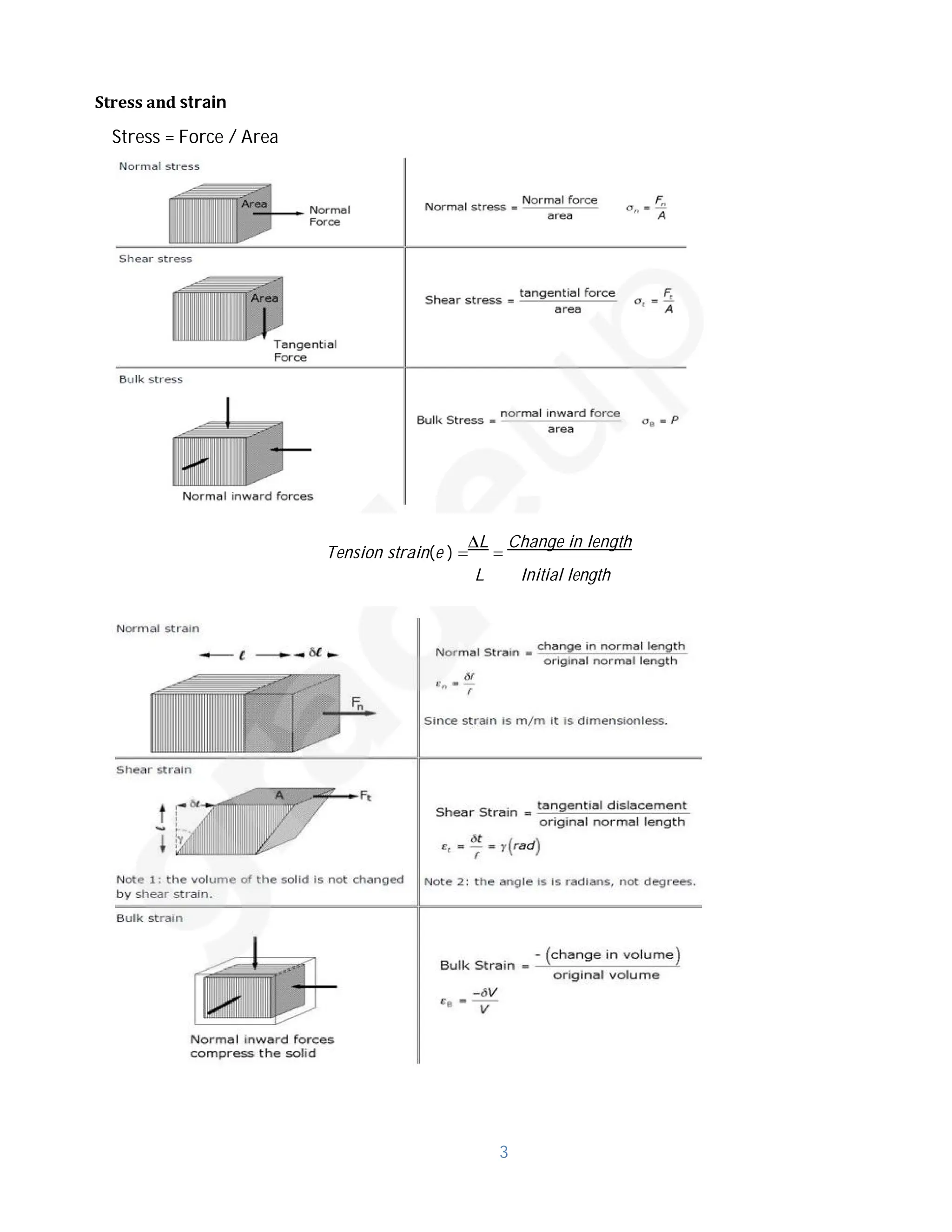
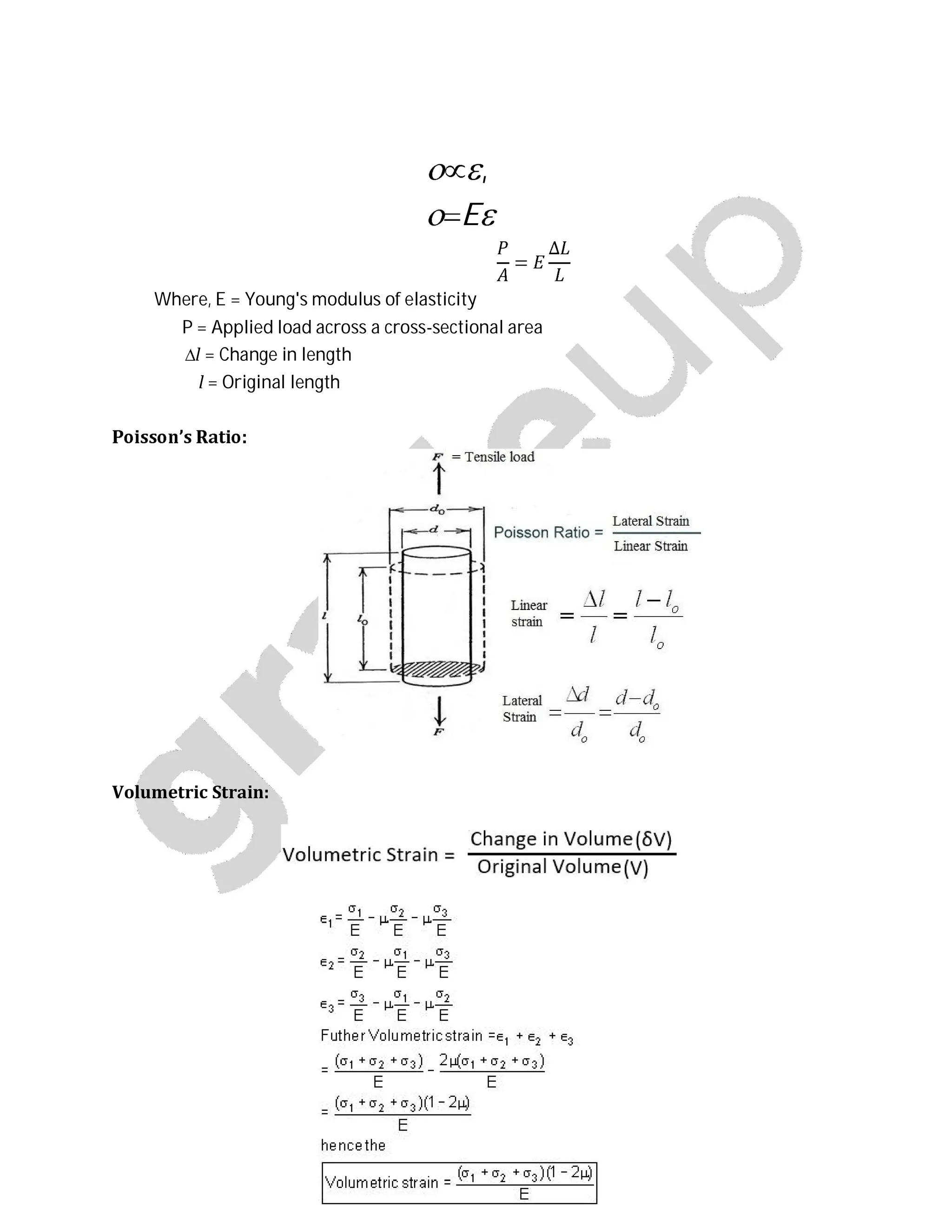
- Stress and strain definitions and formulas for tension and compression.
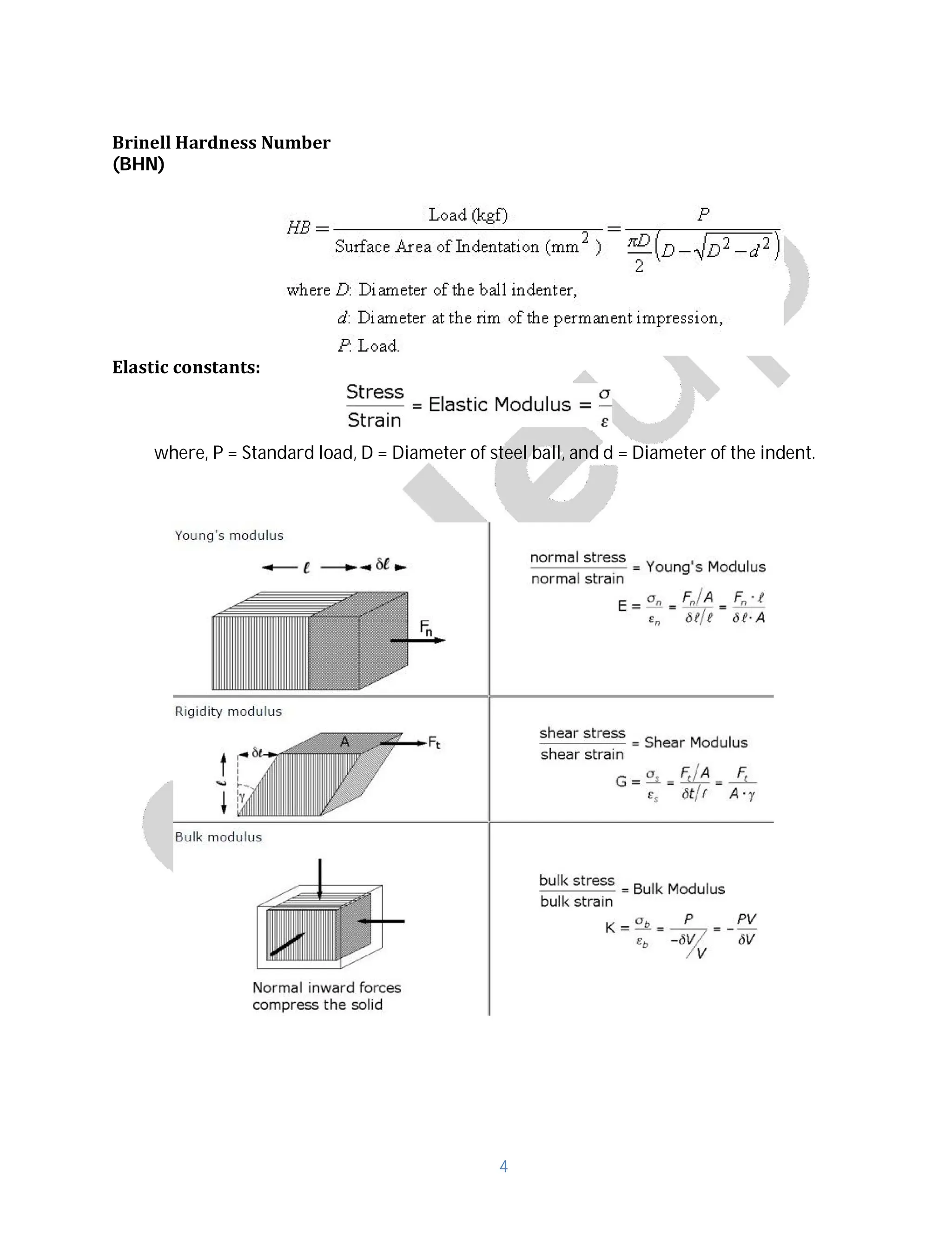
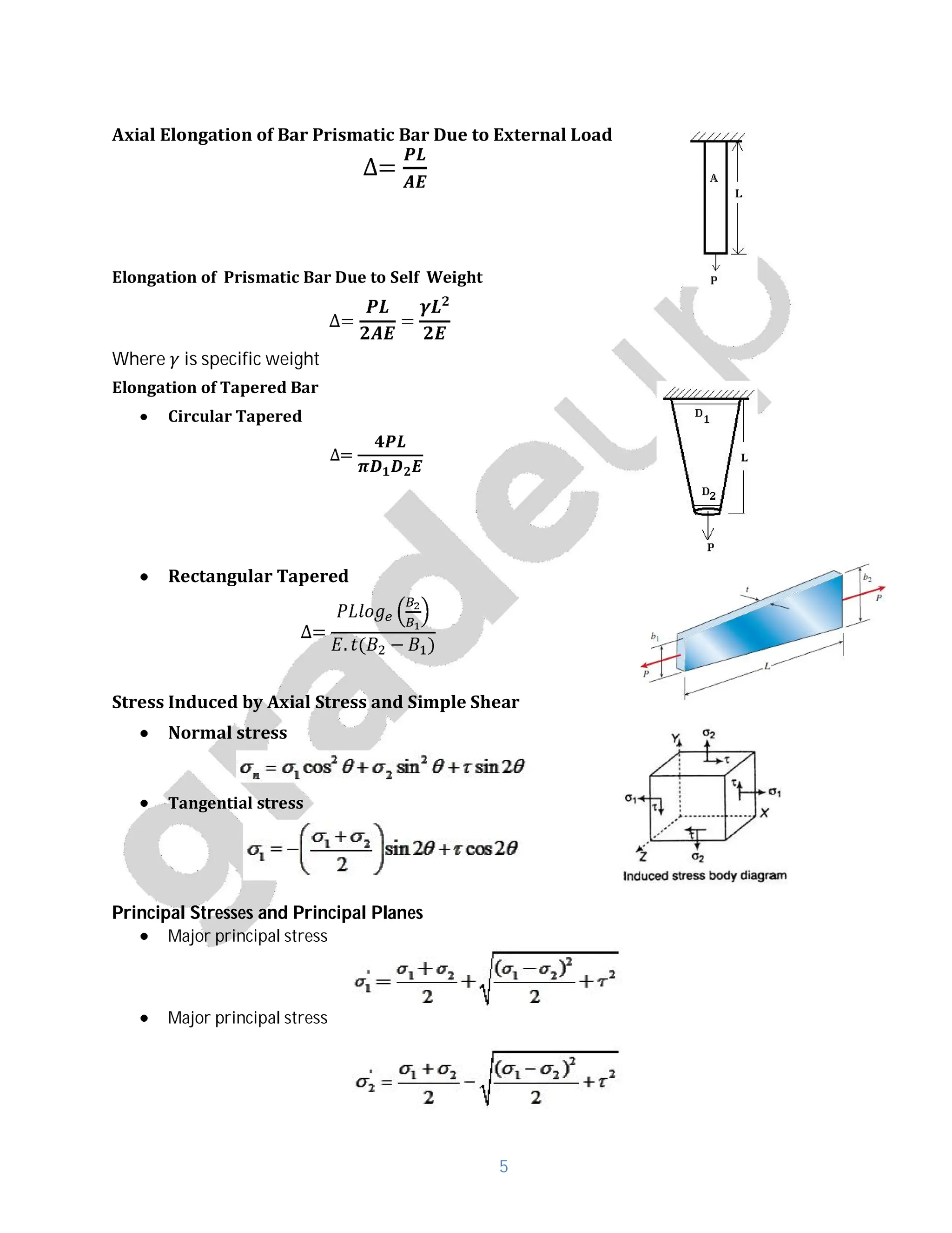
- Formulas for calculating Brinell hardness number, axial elongation of bars, and stresses induced by axial and shear loads.
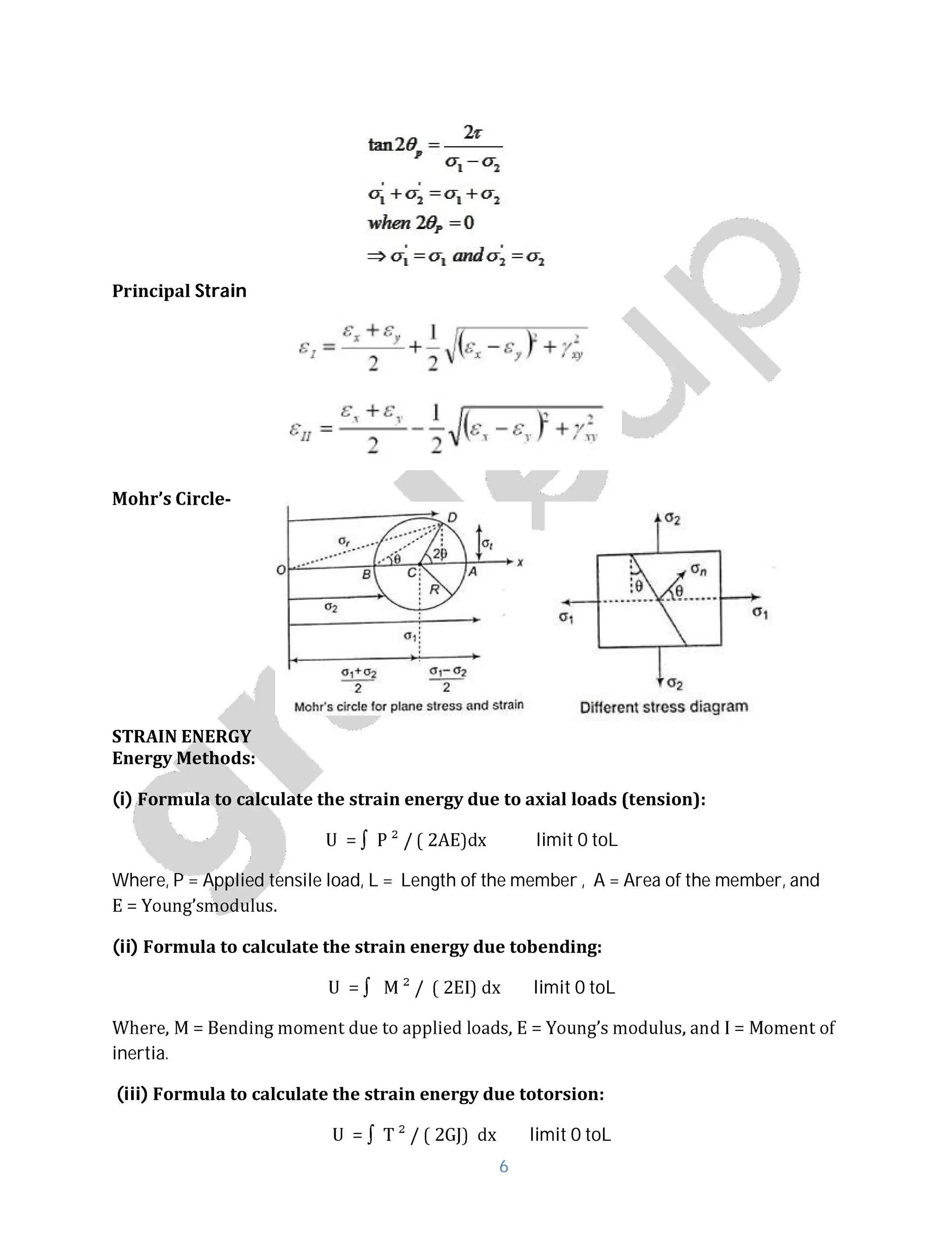
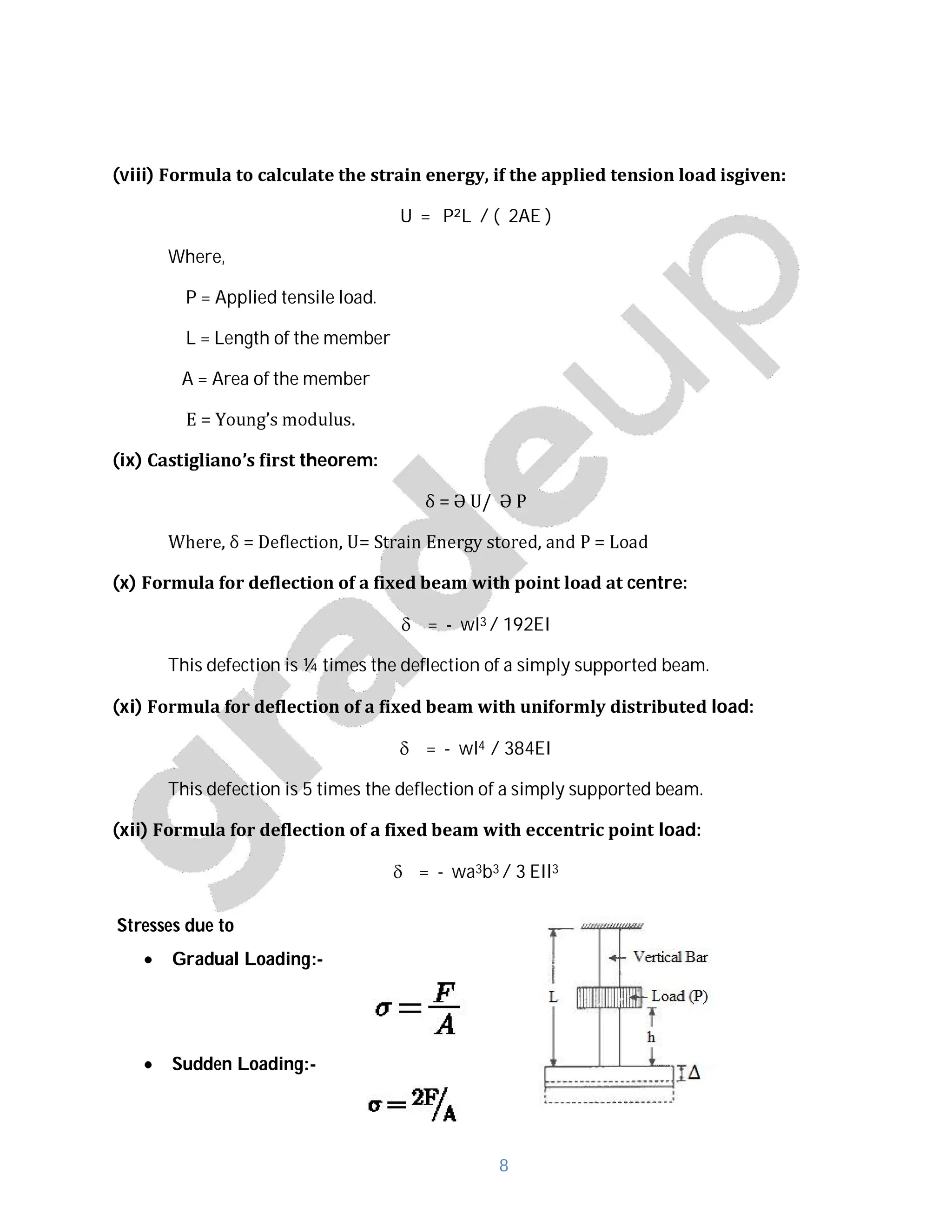
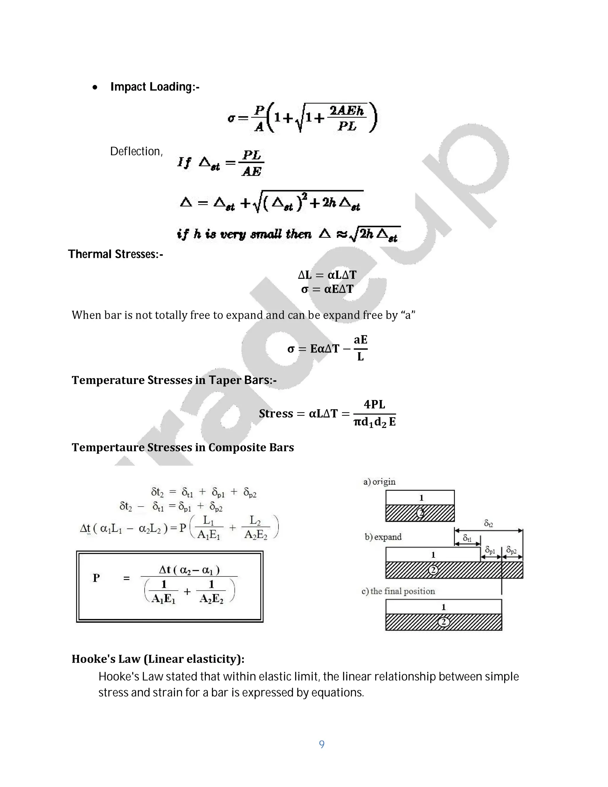
- Concepts of principal stresses and strains, strain energy, deflection, thermal stresses, Hooke's law, and stresses in thin shells.
- Relationships between modulus of elasticity, shear modulus, bulk modulus, and Poisson's ratio.
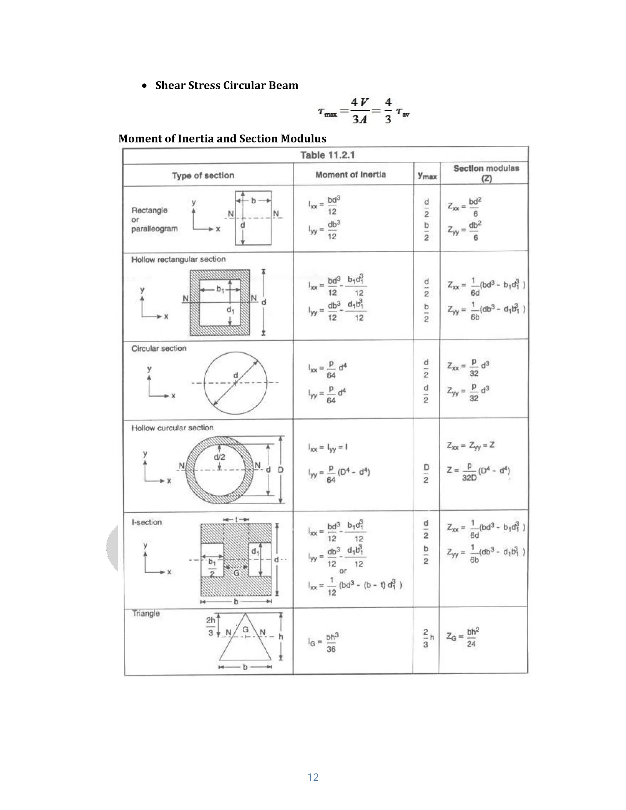
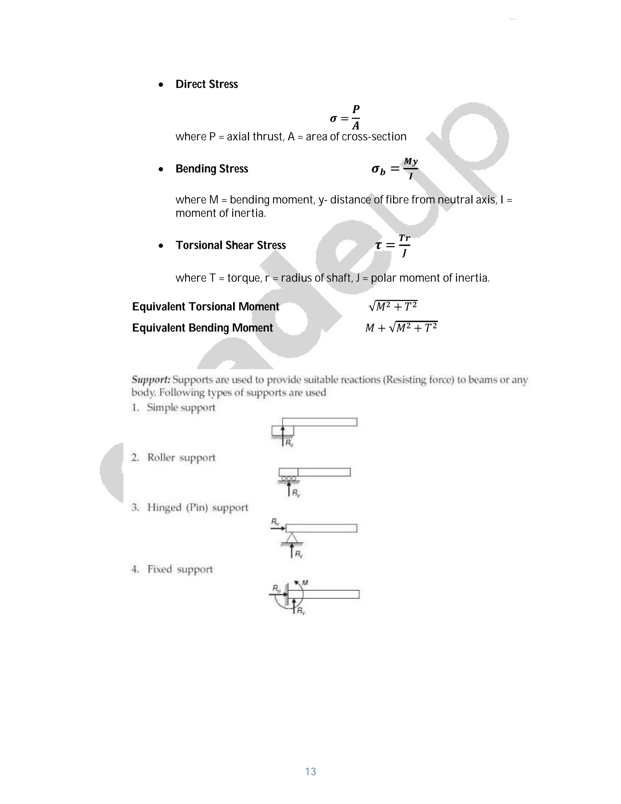
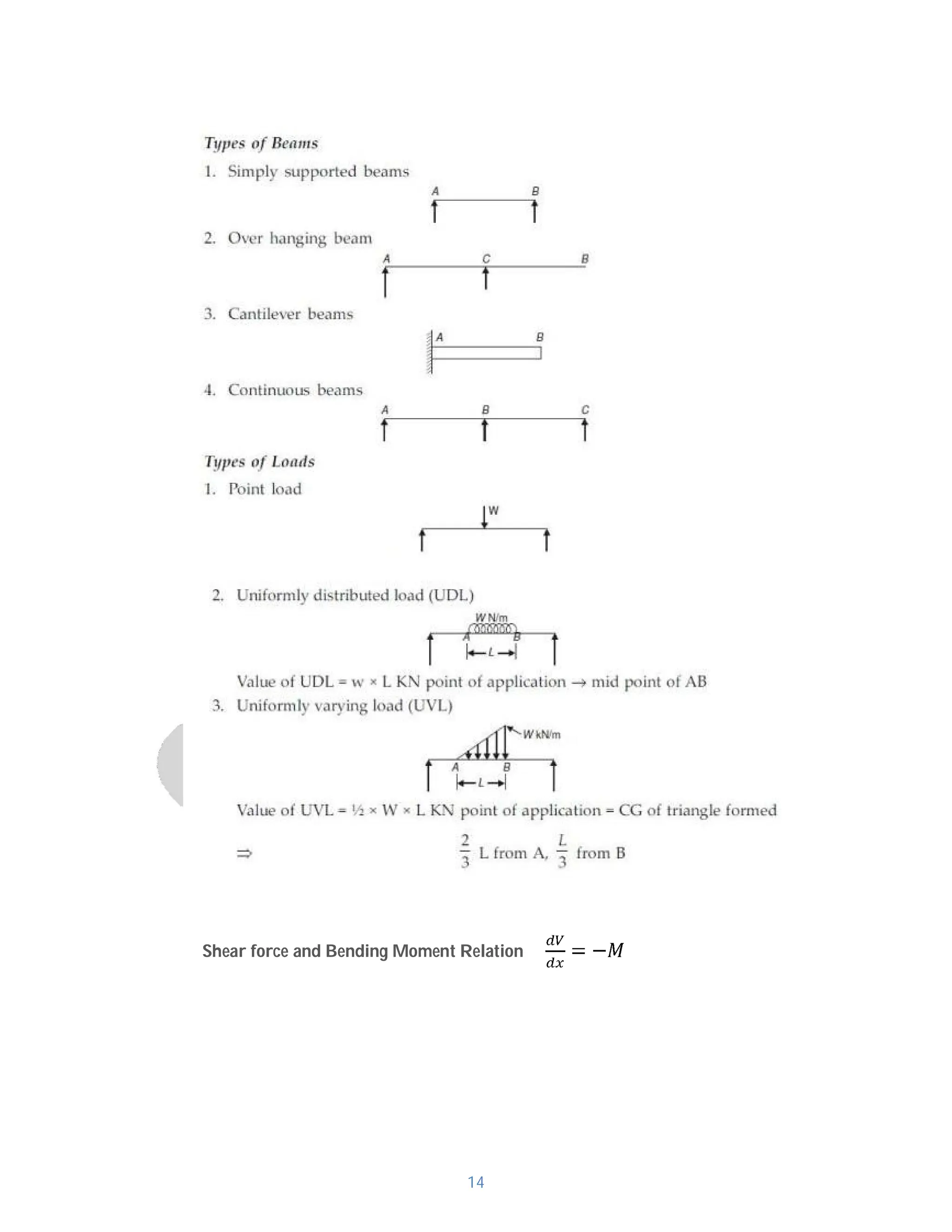
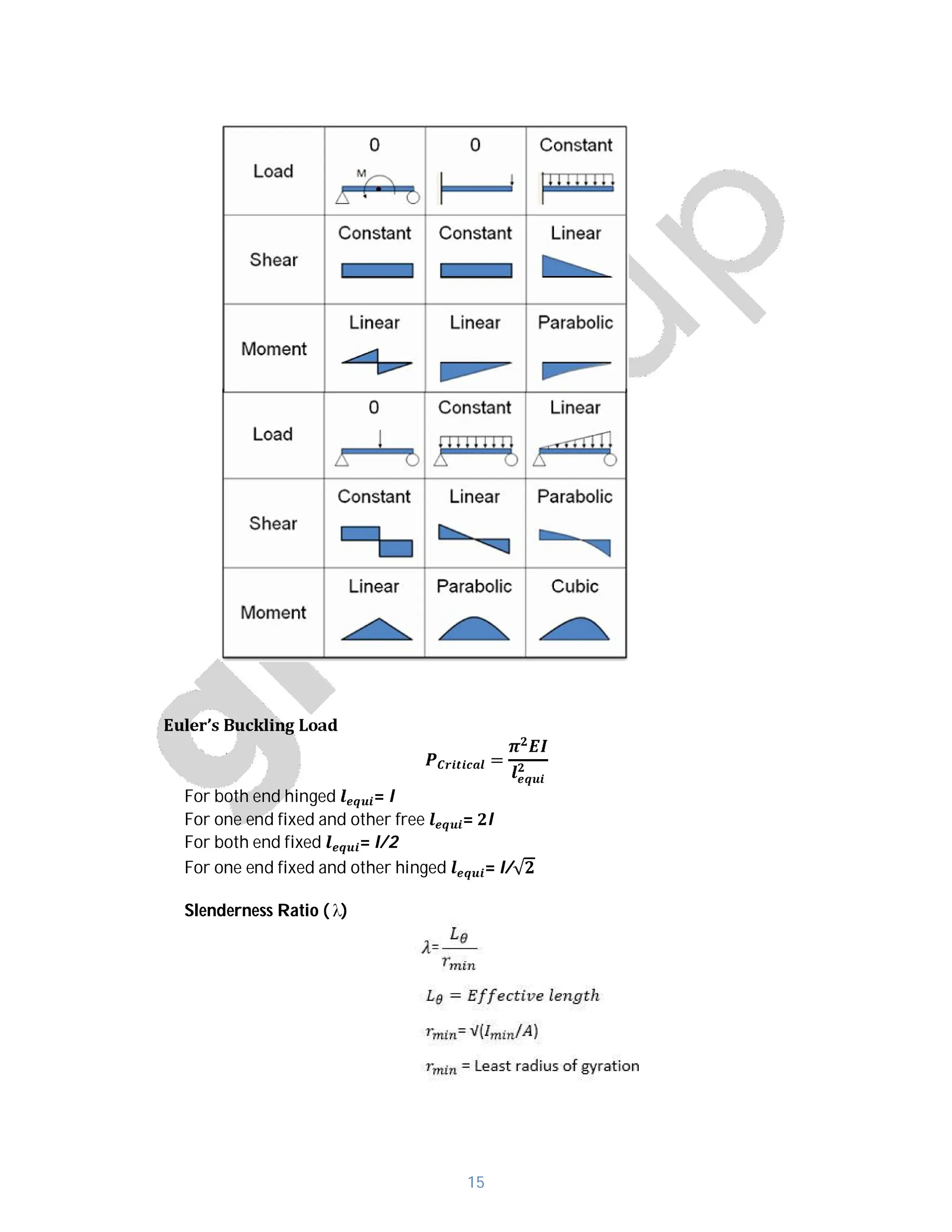
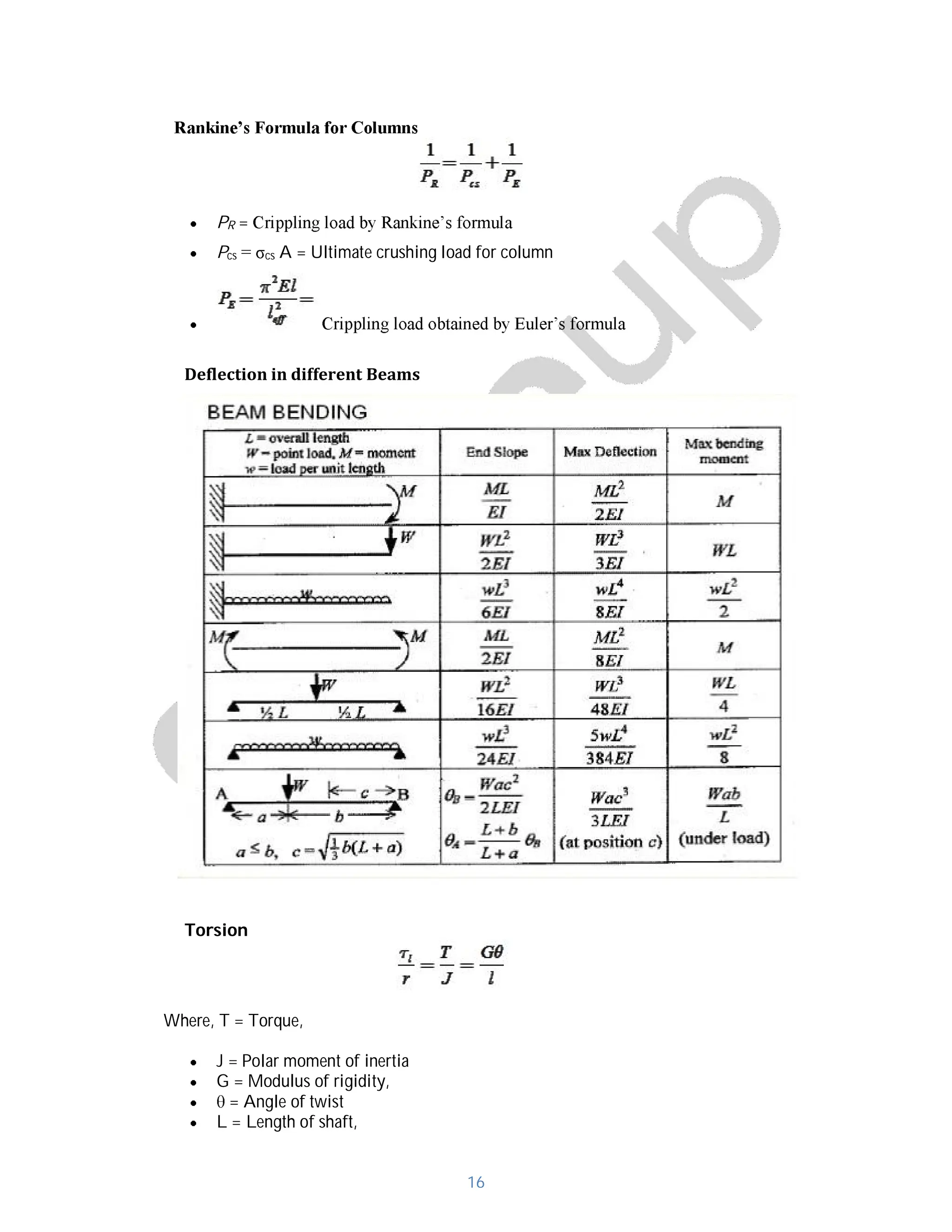
- Formulas for shear stress in beams, bending stress, torsional shear stress, shear force and bending moments.