This document summarizes key concepts in concrete structural design including:
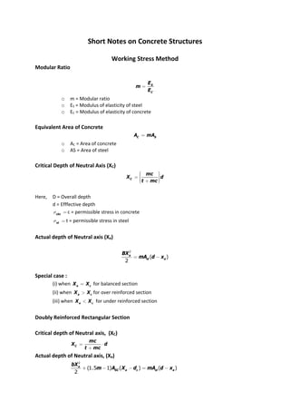
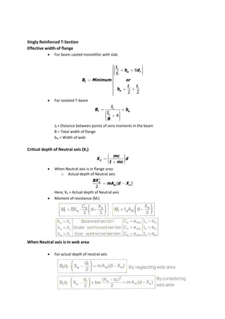
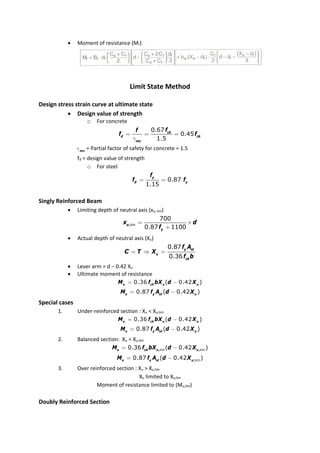
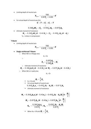
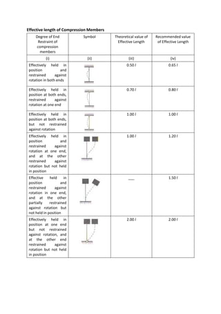
1) The working stress and limit state methods for design of reinforced concrete beams, slabs, and columns. It covers topics like modular ratio, neutral axis depth, reinforcement ratios, and shear design.
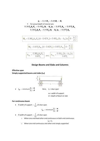
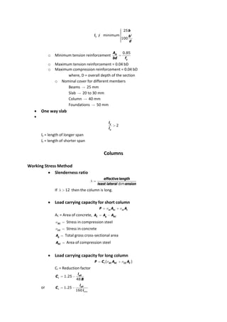
2) Design considerations for different structural elements like singly and doubly reinforced beams, T-beams, and columns. It provides equations for calculating load capacity.
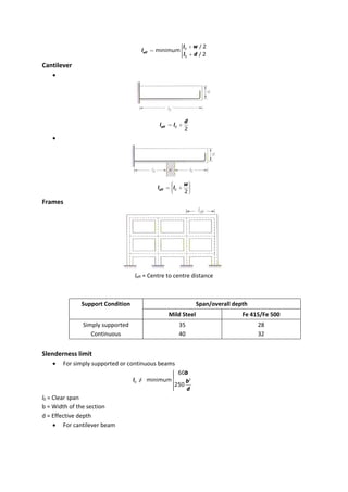
3) Additional topics on bond, anchorage, development length, and effective spans for different support conditions.