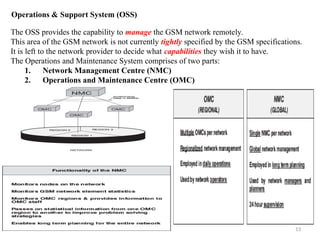
# Cellular Mobile Communication
## 1. Introduction
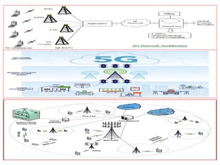
Cellular mobile communication is one of the most transformative technologies of the modern era, fundamentally reshaping how people interact, access information, and conduct business. From simple voice calls to high-speed multimedia services, cellular systems have evolved to support a vast range of applications including video streaming, mobile banking, telemedicine, smart transportation, and the Internet of Things (IoT). The term *cellular* refers to the division of a large geographical service area into smaller regions called *cells*, each served by a base station. This architecture enables efficient frequency reuse, higher system capacity, and seamless mobility for users.
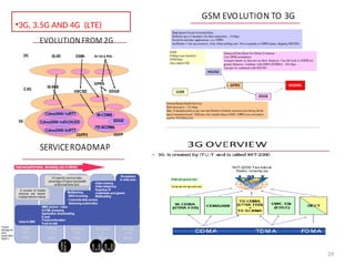
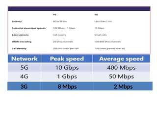
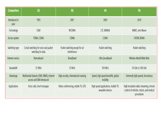
The rapid growth in mobile subscribers, data demand, and device diversity has driven continuous innovation in cellular communication technologies. Over successive generations—1G through 5G and beyond—cellular systems have progressed from analog voice services to fully digital, packet-switched, broadband wireless networks. This document presents a comprehensive overview of cellular mobile communication, covering its principles, system architecture, multiple access techniques, generations, propagation issues, performance metrics, and future trends.
## 2. Fundamentals of Cellular Concept
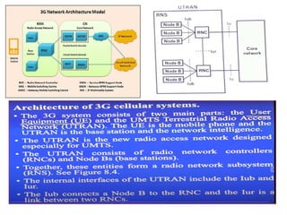
The cellular concept was introduced to overcome the limitations of early mobile radio systems, which used a single high-power transmitter to cover a large area. Such systems suffered from poor spectral efficiency, limited capacity, and severe interference. In contrast, a cellular system divides the coverage area into multiple smaller cells, each with its own low-power base station (BS).
### 2.1 Cell Structure and Frequency Reuse
Each cell is allocated a set of frequency channels. Adjacent cells use different frequency sets to avoid interference, while cells sufficiently far apart can reuse the same frequencies. This principle, known as *frequency reuse*, significantly increases the number of users that can be supported within a given bandwidth.
The reuse factor depends on the cluster size, typically denoted by *N*, which represents the number of cells in a cluster using unique frequency sets. Smaller cluster sizes improve spectral efficiency but increase co-channel interference, requiring careful planning and interference management.
### 2.2 Handoff (Handover)
As a mobile user moves across cell boundaries, the ongoing call or data session must be transferred from one base station to another without noticeable interruption. This process is called *handoff* or *handover*. Efficient handoff algorithms are critical for maintaining quality of service (QoS), especially in high-mobility scenarios.
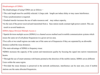
Handoffs can be classified as hard or soft. In hard handoff, the connection with the current base station is released before establishing a new one. In soft handoff, used in CDMA-based systems, the mobile station may be simultaneously connected to m