


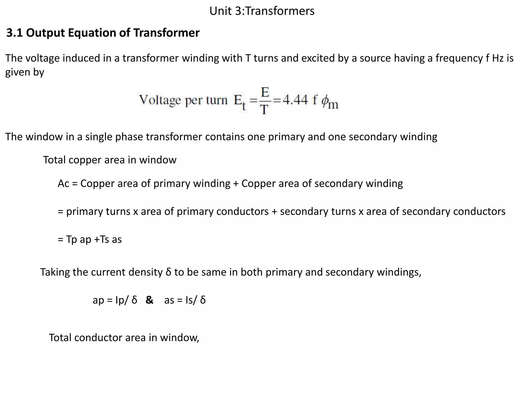
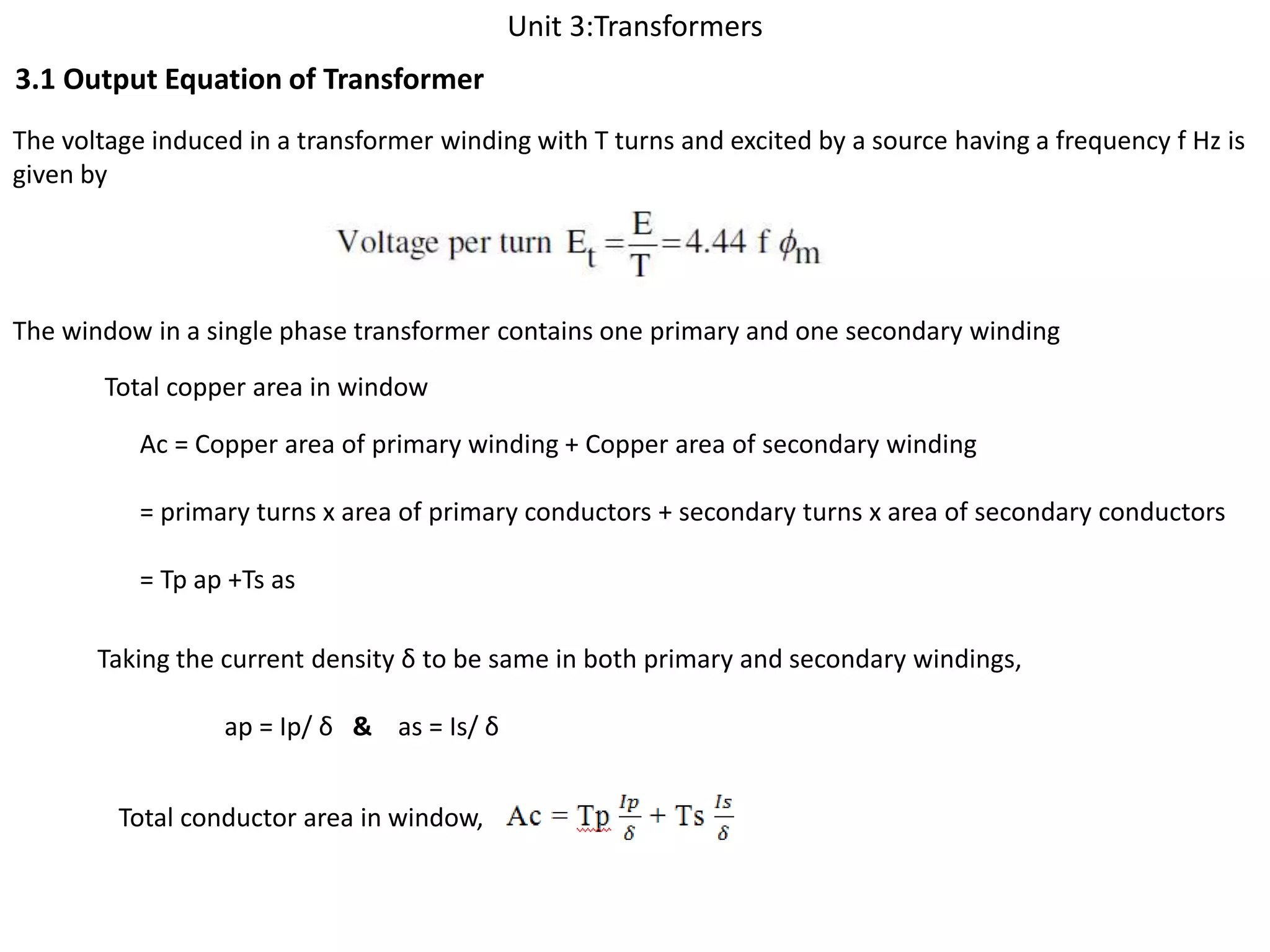


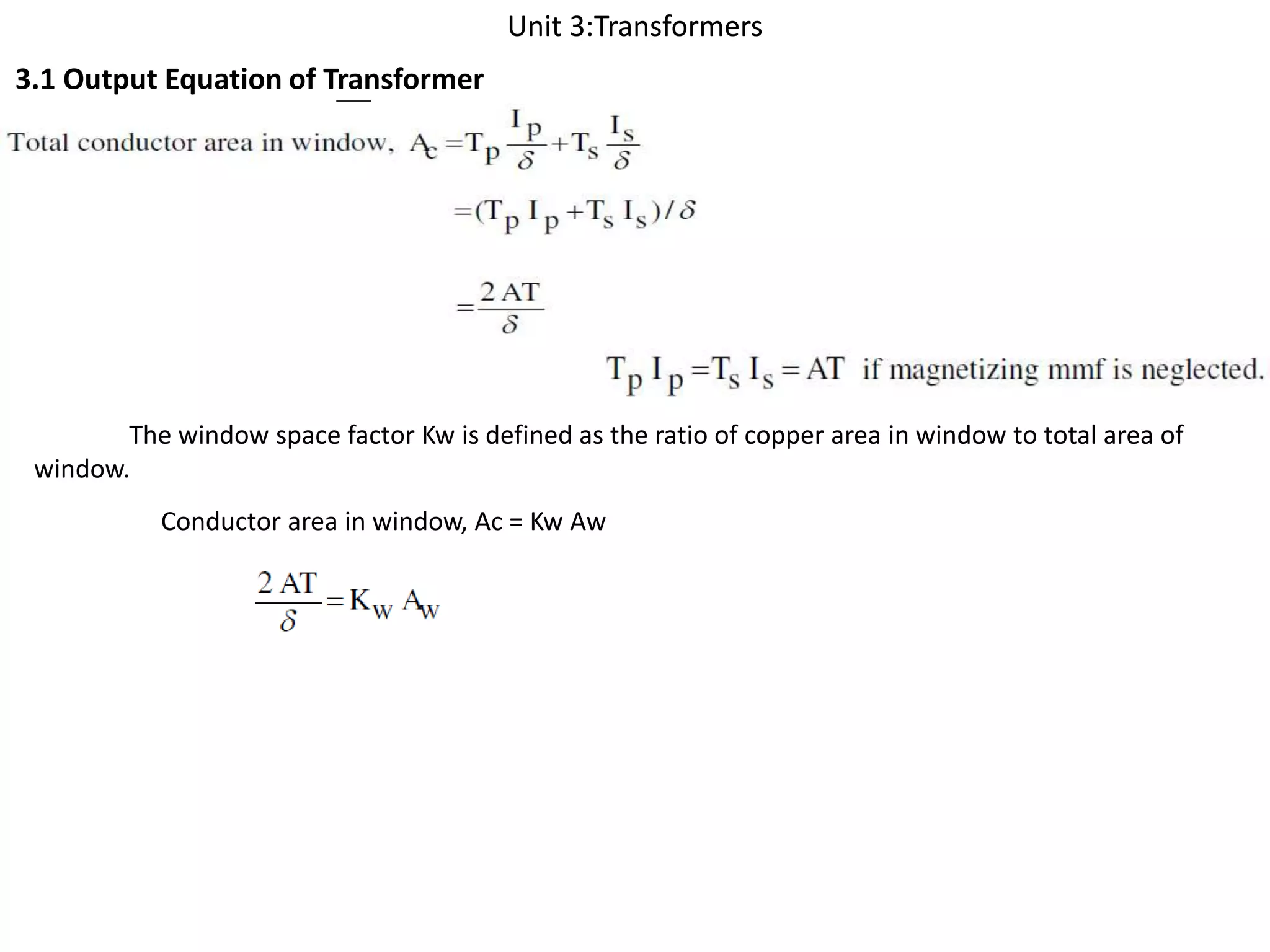


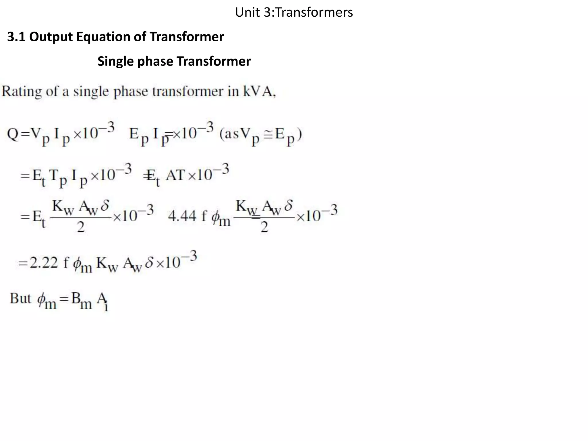


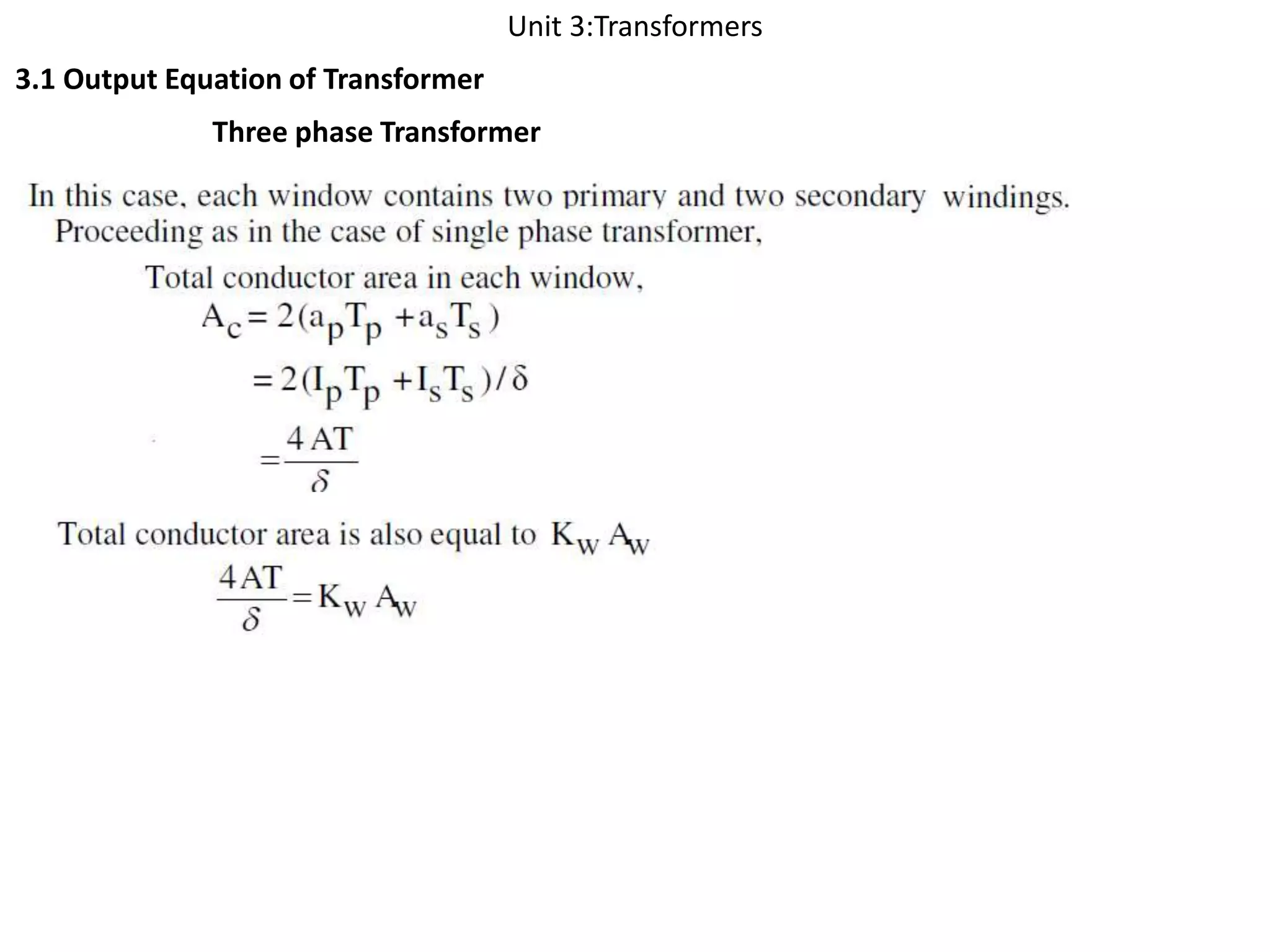


The document discusses the output equation of transformers. It explains that the voltage induced in a transformer winding is determined by factors like the number of turns and the source frequency. It also describes components of a single-phase and three-phase transformer like the primary and secondary windings contained in the transformer window. Equations are provided for calculating the copper area required based on current density and turns ratio between windings.
Discussion on output equations and voltage induction in transformers with primary and secondary windings.
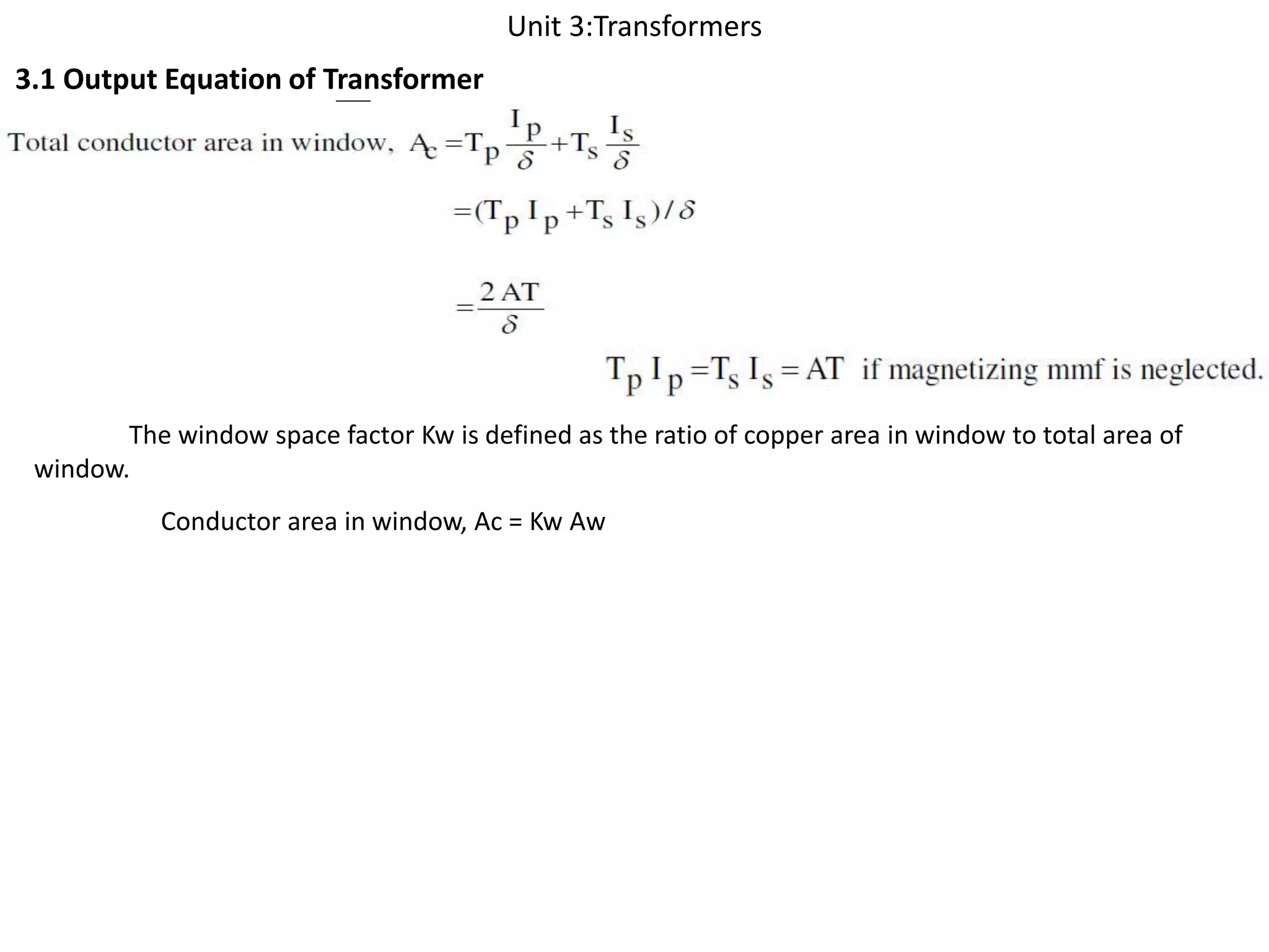
Introduction to window space factor (Kw) and its significance in the context of transformer conductor areas.
Overview of single phase transformers, focusing on their design and functional characteristics.
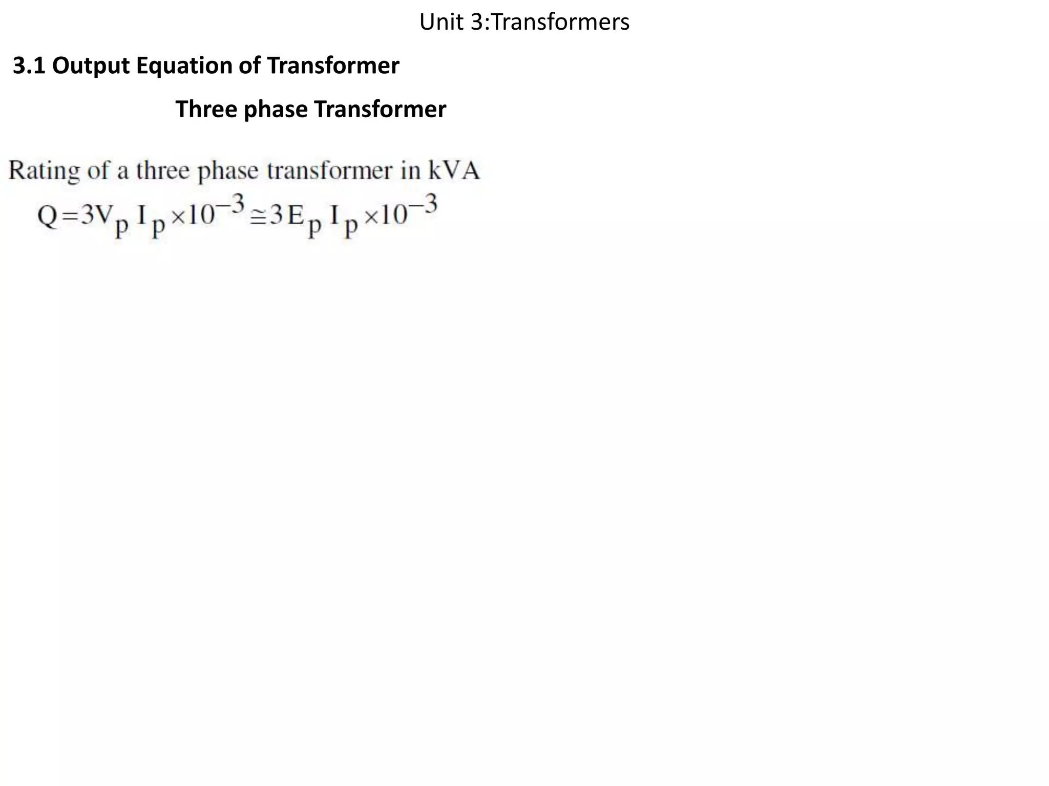
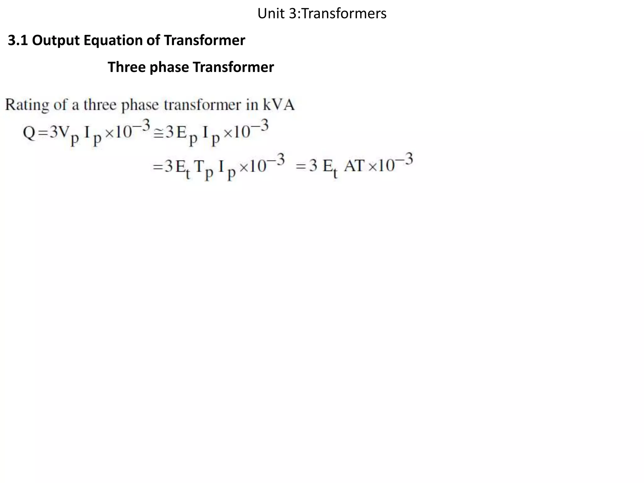
Overview of three phase transformers, concentrating on design, features, and operational principles.


