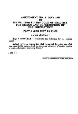
This document provides guidelines for load testing of piles used in foundations. It discusses different types of load tests, including vertical, lateral, and pull-out tests. The guidelines cover determining ultimate and safe load capacities from initial load tests, as well as routine load tests to check working piles. Procedures for applying test loads using dead weights and measuring displacements are also outlined. The purpose is to provide a standardized approach for evaluating pile performance and capacities through in-situ load testing.
This document provides information on bridge planning, design, classification and components. It discusses:
1. The key steps in bridge planning including studying needs, alternatives, design and implementation.
2. Common bridge classifications including material (masonry, concrete, steel), structural type (slab, girder, truss), and purpose (road, rail).
3. The main components of a typical T-beam bridge including the deck slab, longitudinal girders, cross girders, abutments and foundations. Methods for designing the deck slab and cantilever portions are outlined.
This document provides information about a project involving the construction of pile foundations using the bored cast-in-situ piling method at an English Medium High Madrasha site in Malda. It includes details of the project such as the estimated and tender costs, concrete mix design, pile load testing procedures, and descriptions of the pile classification, boring and concreting process. Reinforcement details and specifications for equipment used in the piling like DMC pipes, tremie pipes, chisel, and casing are also provided.
1. Load-settlement curves for footings on dense sand or stiff clay show a pronounced peak and failure occurs at very small strains, with sudden sinking or tilting and surface heaving of adjoining soil.
2. For medium sand or clay, failure starts at a localized spot and migrates outward gradually, with large vertical strains and small lateral strains. Failure planes are not clearly defined.
3. Failure zones for footings on slopes do not extend above the horizontal plane through the base, and failure occurs when downward and upward pressures are equal.
Rigid pavements are concrete slabs that distribute vehicle loads through beam action. They have high flexural strength and small deflections compared to flexible pavements. The presentation discusses the types of rigid pavements including jointed plain concrete, jointed reinforced concrete, and continuously reinforced concrete pavements. It also covers the design factors for rigid pavements such as traffic loading, subgrade strength, environmental conditions, and material properties. Rigid pavements are designed to last 30 years with minimal maintenance required over the design life.
The document provides information on the New Austrian Tunneling Method (NATM). It discusses the history and origins of NATM, highlighting its first use in Austria in the 1960s. The document also outlines the key principles and features of NATM, including mobilizing the strength of the rock mass, shotcrete protection, measurements, primary lining, closing the invert, rock mass classification, and dynamic design. The sequence of executing a tunnel using the NATM approach is also described.
The document provides instructions for conducting pull-out tests to determine the compressive strength of concrete. It states that pull-out tests should be confirmed to BS 1881 Part 207 and give a direct tensile strength value. It describes how inserts can be cast into wet concrete or positioned in hardened concrete using an under-reamed groove. When testing, at least four pull-out tests should be performed at each location and a loading rate of 0.5 ± 0.2 kN/s should be used for 25mm diameter inserts. The compressive strength can then be calculated from the direct tensile strength value obtained during testing.
1. The standard penetration test (SPT) involves driving a split-spoon sampler into the ground using a 63.5 kg hammer dropped from a height of 0.76 m. The number of blows required to drive the sampler over two intervals of 150 mm each is recorded as the SPT N-value.
2. The SPT N-value provides an approximate measure of soil resistance and a disturbed soil sample. It can be used to estimate soil strength parameters and bearing capacity through empirical correlations.
3. However, the SPT is highly dependent on the equipment and operator used, as factors like hammer efficiency, drill rod length, and borehole diameter can affect the N-value. Corrections are required
This document provides information on reinforced earth walls, including their components and construction methodology. It discusses that reinforced earth walls combine earth and linear reinforcing strips to bear large tensile stresses. The key components are reinforcing elements, soil backfill (which can be replaced with fly ash), and a facing element. Geogrids are used as reinforcements and provide strength in tension, while fly ash or soil in the backfill provides compression strength. The document also outlines design considerations around drainage, joint materials, and stability checks for these types of walls.
Grillage Analysis of T-Beam bridge, Box culvert and their Limit State Design; components of Bridges and loads acting on bridges are presented in this slide.
Pile foundation is important for construction of foundation where bearing capacity of soil is poor. Pile foundation is use for distribution of uneven load of superstructure.There are so many type of pile are use for construction. Here i present some of pile with suitable condition for construction and methods for construction.
Thank you.
This document provides information about the design of strap footings. It begins with an overview of strap footings, noting they are used to connect an eccentrically loaded column footing to an interior column. The strap transmits moment caused by eccentricity to the interior footing to generate uniform soil pressure beneath both footings.
It then outlines the basic considerations for strap footing design: 1) the strap must be rigid, 2) footings should have equal soil pressures to avoid differential settlement, and 3) the strap should be out of contact with soil to avoid soil reactions. Finally, it provides the step-by-step process for designing a strap footing, including proportioning footing dimensions, evaluating soil pressures, designing reinforcement,
This document summarizes the procedures for conducting a pile load test to determine the load carrying capacity of a pile. The test involves installing a test pile between two anchor piles and applying incremental loads through a hydraulic jack while monitoring settlement. Loads are applied until the pile reaches twice its safe load or a specified settlement. A load-settlement curve is plotted to determine the ultimate load and safe load based on settlement criteria. The test provides values for maximum load, permissible working load, and pile settlement under different loads.
1. The document discusses different types of settlement in shallow foundations, including immediate/elastic settlement, primary consolidation settlement, and secondary consolidation settlement.
2. It provides methods for calculating each type of settlement, making use of theories of elasticity, consolidation test data, and parameters like compression index.
3. Settlement predictions are generally satisfactory but better for inorganic clays; the time rate of consolidation settlement is often poorly estimated.
Dynamic pile formulae estimate the ultimate load capacity of driven piles based on data collected during pile driving. The Engineering News formula is the simplest and most used dynamic formula. It relates the ultimate load capacity to the weight of the hammer, height of fall, and pile penetration per blow. The Modified Hiley's formula improves upon the Engineering News formula by accounting for energy losses during driving. Limitations of dynamic formulae include not representing the static load capacity and being unsuitable for cohesive soils where pore pressures can develop.
This document provides a summary of a book on concrete bridge design according to BS 5400. The book aims to provide guidance on applying the limit state design code for concrete bridges by explaining its clauses and comparing them to previous design standards. It discusses analysis methods, loadings, material properties, design criteria, and worked examples to illustrate the code's application to bridge elements like beams, slabs, foundations and composite construction.
Structural strengthening, restoring and adding capacity is an integral part of today’s concrete repair industry. Structural strengthening may be required for increasing load capacity of beams, columns, walls, and/or slabs, seismic retrofitting, supporting additional live or dead loads not included in original design, to relieve stresses generated by design or construction errors, or to restore original load capacity to damaged structural elements.
Pile foundations extend deep below buildings to support heavy loads on poor soil conditions. There are different types of piles including wood, steel, and concrete piles that are installed using various methods such as driving, drilling, or jacking. Piles can be classified based on their material, load transfer method, degree of soil displacement during installation, and installation method. Common types include end bearing piles that transfer load to firm soil at depth and friction piles that transfer load along their shaft through skin friction with surrounding soil.
This document describes the California Bearing Ratio (CBR) test, which is used to determine the strength of soils and granular materials for pavement design. The CBR test involves compacting a soil sample and measuring the penetration of a piston under increasing loads. The CBR value is the load required to penetrate the sample 2.5mm or 5mm divided by a standard load value. Higher CBR values indicate stronger soils suitable for supporting pavement layers. The document outlines the apparatus, test procedure, interpretation of results, and classification of subgrade strength based on CBR values.
The document describes designing a simple beam using STAAD.Pro software. It involves generating the beam geometry, applying loads and supports, analyzing the beam, and designing the beam for concrete. Key steps include assigning the beam properties, applying a fixed support at one end and distributed and point loads, obtaining the loading diagram, shear force and bending moment diagrams, and running the concrete design. The output includes structural drawings, input files, concrete takeoff, and beam design details.
Rigid pavements are constructed using reinforced concrete slabs that provide a strong wearing surface and base course. They are used in areas with adverse conditions like heavy rainfall, poor soil/drainage, or extreme climate. Materials for rigid pavements include Portland cement, coarse and fine aggregates, and water. Reinforcement includes dowel bars at joints. Rigid pavements have longitudinal and transverse joints, including contraction joints to relieve stresses, expansion joints to allow for expansion, and construction joints. They can be constructed using slipform pavers, fixed form pavers, or manual methods. Quality control checks materials and finished surface properties. Traffic is allowed after a minimum 28-day curing period.
Bridge loading and bridge design fundamentalsMadujith Sagara
This document discusses bridge loading standards and load evaluation for bridge design according to Eurocode standards. It provides definitions of key terms like carriageway and notional lane used in evaluating bridge loads. It summarizes the four load models specified in Eurocode 1-2 for determining effects of road traffic on bridges, including concentrated tandem loads and uniform loads in Load Model 1, single axle loads in Load Model 2, special abnormal vehicles in Load Model 3, and uniform crowd loads in Load Model 4. Diagrams show how these loads are applied to the notional lanes of a bridge carriageway for analysis. Groups of simultaneous traffic loads are also defined for combination with other actions.
1) The document presents the results of an unconsolidated undrained (UU) triaxial test conducted by a group of 6 students on remolded soil specimens.
2) The UU test involves applying confining pressure to an unsaturated soil sample and shearing it undrained to determine the shear strength parameters. 3 tests were conducted at different confining pressures.
3) The first two tests yielded undrained shear strengths of 45.9 psi and 42.35 psi, while the third test gave a higher value of 55.39 psi, which may not be valid due to partial saturation of that sample.
The document discusses properties and testing of concrete. It provides information on the constituents of concrete including cement, coarse aggregate, fine aggregate, and water. It also discusses properties of concrete and reinforcements, including their relatively high compressive strength and lower tensile strength. Various tests performed on concrete are mentioned, including tests on workability, compressive strength, flexural strength, and fresh/hardened concrete. Design philosophies for reinforced concrete include the working stress method, ultimate strength method, and limit state method.
The document discusses construction progress on a 20 classroom boys' school expansion project in Sur Hilal, Al-Suwaiq, Batinah North Governorate. It outlines various tests and works completed on the concrete filled auger pile foundations, including low strain integrity testing, concrete temperature and slump tests, boring piles to depths of 1m and 13m below ground, and installing rebar cages. It also details works on pile caps, including excavation, trimming piles, formwork, pouring and testing concrete, as well as a static load test on pile 71. Levelling and compaction works were also conducted for an irrigation tank.
The document discusses pile foundations and their design. It describes different types of piles including end bearing piles, friction piles, displacement piles, and replacement piles. It covers topics such as pile capacity calculation considering end bearing and skin friction, methods of installation, failure modes, total and effective stress analysis, and prediction of pile capacity through pile driving formulas and load testing.
PILE FOUNDATION PROJECT TRAINING ANSHULAnshul Shakya
This document summarizes a seminar presentation on pile foundation work for a residential building project in Greater Noida. It describes the project details, including 9 towers of G+22 floors with 4 flats per floor. It then covers Indian standards for pile foundations, basic concepts of pile capacity calculation, equipment used, site specifications, materials, installation process, cage detailing, and column casting process.
The document discusses different types of pile foundations. It begins by explaining that pile foundations transfer structural loads through weak soil layers to stronger layers below. It then describes different types of piles based on their function (load bearing, sheet), material (wood, concrete, steel), and installation method (driven, precast). Key points covered include how end bearing, friction, and composite piles transmit loads differently. The document also lists situations where pile foundations are necessary and advantages/disadvantages of different pile materials.
This document discusses pile foundations. Piles are structural members made of materials like steel, concrete, or timber that are driven into the ground to support buildings on weak soils. There are two main types of piles: end bearing piles that extend to bedrock, and friction piles that gain support through friction in the soil when no bedrock is present. Pile caps are used to distribute loads from the structure to multiple piles. Reinforcement in the pile cap resists tensile and shear forces. The document provides schematics and comparisons of different pile foundation construction methods.
This document provides information about pile foundations. Pile foundations are used when the soil cannot support building loads and piles are driven deep into the ground until they reach a bearing stratum. Piles can be made of timber, concrete, or steel. They transfer loads from the building to the stronger subsurface layer. The document discusses different types of piles including end bearing and friction piles and explains how pile caps are reinforced to resist tensile and shear forces from heavy loads. Diagrams show how pile foundations are arranged and how piles transmit loads into the ground.
types of Foundations with animated sketchesGiri Babu S V
This document discusses different types of foundations used to support structures. It begins by stating the objectives are to understand foundation construction, types of foundations, and which are suitable for different soil types. It then defines foundations as the lowest part of a structure below ground that transmits the weight to the subsoil. The main types discussed are shallow foundations, which include wall, column, combined, and mat foundations, and deep foundations, such as pile, under-reamed pile, and well foundations. Specific foundation types like isolated column, combined, mat, pile, under-reamed pile and well foundations are then described in more detail.
This document provides guidelines for the design and construction of bored precast concrete piles used for foundations. It outlines necessary site investigation information needed, equipment used, and design considerations. Bored precast piles involve boring holes and lowering precast concrete piles that are then grouted in place. Proper site data on soil conditions, groundwater levels, and structural loading is required. Equipment for boring, handling, and grouting the piles must be selected based on subsoil properties. Pile design should ensure loads are safely transmitted to the soil without failure or excessive settlement.
This document provides information on Indian Standard IS:2911 regarding the design and construction of pile foundations. It outlines the necessary members of the committee working on revising the standard. The standard covers driven precast concrete piles, providing guidance on pile design, construction methods, site investigation needs, and other relevant details. It aims to incorporate recent developments in pile foundation engineering practices in India.
This document provides guidelines for the design and construction of under-reamed piles. Under-reamed piles are bored cast in situ or bored compaction concrete piles that have one or more enlarged bulbs formed along the pile stem. They are used in a variety of soil conditions to provide increased bearing capacity, anchorage against uplift, and to reach firm strata below weak or filled soils. The document outlines the necessary site investigation and structural design information required for the satisfactory design and construction of under-reamed pile foundations. It also defines relevant terminology and describes the types and purposes of different pile load tests.
This document provides the summary of an Indian Standard code of practice for the design and construction of pile foundations. It specifically focuses on Section 2 which covers bored cast-in-situ concrete piles. Key points include:
1) It establishes terminology for bored cast-in-situ piles which are formed by excavating a hole in the ground and filling it with concrete, with or without a temporary casing.
2) It provides scope and covers the design and construction of bored concrete piles up to 2,500mm in diameter that transmit structural loads through end-bearing and/or shaft friction.
3) The standard references other related Indian Standards and international codes that were consulted in developing this practice.
This document provides guidance on the design and construction of timber pile foundations. It defines various terms related to timber piles and pile foundations. It outlines the necessary site investigation and structural design information required for pile foundation design. It also describes common equipment and accessories used for timber pile installation, including hammers, casings, and frames. The document emphasizes that pile foundations should be designed to transfer structural loads to the soil without causing soil failure or unacceptable settlements.
The document describes Indian Standard code IS:2911 (Part I/Sec I) - 1979 which provides guidelines for the design and construction of driven cast in-situ concrete pile foundations. It covers necessary considerations for pile type, size, installation depth, load testing, and other factors based on site conditions and project requirements. Subsurface investigation data on soil properties, groundwater levels, and chemical testing is required to properly design and install pile foundations. The standard has been revised to incorporate recent developments and separate pile foundation types into distinct sections for ease of use.
This document provides a code of practice for laying concrete pipes. It includes methods for calculating loads on pipes according to installation conditions and provides corresponding load factors. The purpose is to relate the loads on concrete pipes installed under various conditions to the test strength of the pipe, through appropriate load factors. The document defines key terms, outlines symbols used in calculations, and describes methods to calculate vertical loads on pipes from earth fill material, concentrated loads, and distributed loads. It is intended to be used with other standards for concrete pipes to help ensure pipes are not subjected to loads exceeding their design strength.
This document provides guidelines for the design and construction of raft foundations. It discusses different types of raft foundations and factors to consider in the design such as allowable bearing pressure, depth of foundation, subsoil water pressure, properties of the supporting soil, rigidity of the foundation and superstructure, and methods of analysis. The main methods of analysis described are the conventional or rigid foundation method based on linear distribution of contact pressure, and simplified flexible foundation methods. Design parameters like modulus of elasticity and subgrade reaction are also addressed.
This document provides the Indian Standard methods for testing the jointing of autoclaved cellular concrete flexural members. It outlines the test specimens, jointing procedures, curing processes, testing procedures, and safety considerations. Specimens consist of 5 joined 0.5m concrete elements tested in series of 3. Elements are joined according to manufacturer instructions and cured as directed before testing under centered linear loading to determine joint strength.
This document is an Indian Standard (IS) code of practice for design loads other than earthquakes for buildings and structures. It covers Part 5, which deals with special loads and load combinations to consider in structural design. These special loads include temperature effects, hydrostatic and soil pressures, stresses from creep/shrinkage/settlement, accidental loads, and fatigue from repeated loading. It provides guidance on evaluating and accounting for these special loads and load effects in structural analysis and design. It also discusses appropriate load combinations to consider.
This document is the Indian Standard for earthquake resistant design of structures. It provides guidelines for seismic zoning of India, outlines the revisions made in this fourth version, and lists the committee members involved in developing the standard. The standard aims to ensure structures can withstand earthquakes without structural damage or total collapse. It covers design of buildings, bridges, dams and other structures.
This document outlines testing procedures for evaluating the strength, deformation, and cracking of autoclaved cellular concrete flexural members under short duration bending loads. Key points:
- Test specimens should be full-size structural members to be used in construction.
- Members are simply supported and loaded at third points using steel plates to distribute the load evenly.
- Loads, deflections at mid-span, strains, and crack widths are measured.
- Members are loaded until cracking occurs or a prescribed load is reached to evaluate strength, deformation, and cracking behavior under short term bending loads.
This document outlines testing methods to evaluate bond strength between concrete and reinforcing bars. It describes procedures for pull-out tests using concrete cubes with embedded reinforcing bars. Specimen sizes are based on bar diameters up to 25mm being tested in 150mm cubes, and larger bars in 225mm cubes. Apparatus includes molds, dial micrometers to measure slip, and a testing machine capable of pulling the bar at a specified rate while measuring slip.
This document is the Indian Standard Code of Practice for Prestressed Concrete from 1980. It provides terminology, materials requirements, design considerations, and structural design guidelines for prestressed concrete according to the limit state method. Some key changes from the previous version include introducing concepts of limit state design, provisions for partial prestress, revising shear and torsion design recommendations, and detailing durability requirements. The code aims to unify prestressed concrete design provisions with those for reinforced concrete where applicable.
This document provides the code of practice for the design and construction of conical and hyperbolic paraboloidal shell foundations. It discusses the preliminary design considerations for shell foundations, including determining the soil design to proportion the foundation dimensions based on allowable bearing pressure and net loading intensity, as well as the structural design of the shell. It also provides figures illustrating reinforcement details for conical and hyperbolic paraboloidal shell foundations. The code covers the relevant terminology and information needed for design, and notes the membrane analysis approach is commonly used for structural design of shell foundations.
This document provides details on an Indian standard for concrete vibrators of the screed board type. It outlines:
1. The scope, covering materials, sizes, construction, assembly and performance of screed board concrete vibrators.
2. Terminology for key terms like amplitude of vibration, eccentric shaft, screed board, vibrating unit, etc.
3. Material requirements for parts like the eccentric shaft, tube, rivets, springs and V-belts.
4. Common size designations for screed board vibrators of 3, 4 and 5 meters in length.
5. Construction details covering the mounting of the vibrating unit, positioning, enclosure, lubrication and
This document provides a code of practice for the construction of autoclaved cellular concrete block masonry. It outlines materials and design considerations for constructing load-bearing and non-load bearing walls using these blocks. The document discusses block requirements, mortar mixes, wall thickness, bracing, and modular coordination. It aims to help builders properly use this type of masonry and ensure structural safety and avoidance of cracks.
This document is the Indian Standard Code of Practice for Design Loads (Other than Earthquake) for Buildings and Structures, Part 5 Special Loads and Load Combinations from 1997. It provides guidance on loads to consider in structural design related to temperature effects, hydrostatic and soil pressure, fatigue, and recommendations for appropriate load combinations. Temperature ranges in different parts of India are shown in figures to help assess potential variations. Provisions are made for thermal expansion/contraction and temperature gradients. Soil and water pressures on basement walls and footings are also addressed.
The document is an Indian Standard code of practice for installing joints in concrete pavements. It provides definitions for different types of joints and pavements. It outlines design considerations for the layout and details of transverse and longitudinal joints. It specifies requirements for materials used in joints like joint filler, sealing compounds, and dowel bars. It describes the purpose and details of transverse expansion joints, contraction joints, and construction joints. The code aims to provide guidance on installing joints to control cracking and allow for movement in concrete pavements.
This document outlines test methods for assessing the particle size and shape of aggregates used in concrete from an Indian Standard published in 1963. It includes procedures for sieve analysis to determine particle size distribution, and tests for materials finer than 75 microns, flakiness index, elongation index, and angularity number. The goal is to assist in evaluating the quality of aggregates used in concrete construction in India by testing relevant properties. Maximum sample weights and sieve sizes are provided for different tests.
28-5.21 Company Profile of Pyrmaid structural consultant.pptxBoopathi Yoganathan
Pyramid Structural Consultant provides structural design, building approval, and construction services. They have a team of experienced engineers and workers who use software like AutoCAD and STAAD to complete structural designs for RCC and steel buildings. Notable projects include the design of a G+1 residential building in Namakkal. They are located in Puduchatram, Namakkal and can be found on LinkedIn and Facebook.
This document provides a bonafide certificate for a project report on the study of mechanical properties of eco-friendly economic concrete. It certifies that the project was conducted by three students, M.Vineeth, Y.Boopathi, and P.Murali, in partial fulfillment of their Bachelor of Engineering degree from Kongu Engineering College. The project investigated replacing natural aggregates with steel slag aggregates and M-sand to produce more sustainable concrete. Tests were conducted to determine the compressive strength, split tensile strength, modulus of rupture, and modulus of elasticity of concrete mixes with varying replacement levels.
The document describes an experimental investigation into the properties of concrete with different replacement percentages of natural aggregates with manufactured sand and steel slag. The methodology involves collecting cement, fine aggregates (natural sand and m-sand), coarse aggregates, and steel slag. The mix design for M20 grade concrete is calculated and concrete specimens are cast. The specimens are cured and then tested to determine their mechanical properties. The results are compared to those of conventional concrete to evaluate the suitability of manufactured sand and steel slag as partial replacements for natural aggregates in concrete.
The document discusses two methods for mesh refinement - the p-method and h-method. The p-method increases the order of the polynomial used in the finite element model, allowing for more accurate results without changing the mesh. The h-method reduces the size of elements to create a finer mesh, better approximating the real solution in areas of high stress gradients. Both methods aim to improve the accuracy of finite element analysis results, with the p-method doing so without requiring changes to the mesh.
This document provides guidance on using epoxy injection to repair cracks in concrete structures. The method involves drilling holes along cracks, injecting epoxy under pressure, and allowing it to seep into the cracks. It can repair cracks as small as 0.002 inches. Epoxy injection requires skilled workers and specialized equipment. While it can effectively repair cracks temporarily, the underlying issues causing the cracks may remain if not addressed.
An embedded system is a dedicated computer system that performs specific tasks. An important application of embedded systems is anti-lock braking systems (ABS) in automobiles. ABS uses sensors and electronic control modules to monitor wheel speed and automatically modulate brake pressure to prevent wheel lockup and maintain steering control during emergency braking. By preventing skidding, ABS can help drivers stop more safely and shorten stopping distances on wet or slippery surfaces compared to standard brakes. ABS works by pulsing the brakes rapidly when it detects a wheel is about to lock up, which allows the wheel to continue turning and maintaining traction with the road.
This document discusses past earthquakes in India and retrofitting techniques for masonry structures. It summarizes the 2004 Indian Ocean earthquake and tsunami, which had a magnitude of 9.1-9.3 making it one of the largest ever recorded. Over 230,000 people were killed across 14 countries by the resulting tsunamis. The document then discusses failure modes of confined masonry walls and retrofitting techniques to improve seismic resistance, including adding horizontal reinforcement, improving wall density and tie columns. Key factors for seismic resistance of confined masonry structures are also summarized.
The document provides guidelines for selecting, splicing, installing, and protecting open cable ends for resistance-type measuring devices in concrete and masonry dams. It discusses cable specifications, approved splicing methods including vulcanized rubber splices, rubber sleeve covering, and self-bonding tape. It also covers cable and conduit selection, including choosing the proper conduit size based on the number and size of cables to be run. Proper installation techniques are outlined to protect cable runs within concrete structures.
This document provides information on an Indian Standard (IS) for a unified nomenclature of workmen for civil engineering. It was adopted in 1982 by the Indian Standards Institution Construction Management Sectional Committee. The standard aims to unify the different names used for workmen engaged in civil engineering works across India. It then lists the unified nomenclature for various types of workmen and for carts/animals commonly used in civil engineering works.
This document provides details on the design and construction of floors and roofs using precast reinforced or prestressed concrete ribbed or cored slab units. It specifies dimensions for the precast units, including widths up to 3000mm for ribbed units and 2100mm for cored units. It also provides requirements for material strengths, structural design considerations, and loads to be accounted for in design according to other relevant Indian Standards.
This document provides definitions for key terms related to concrete monolith structures used in port and harbour construction. It defines elements like the bottom plug, cutting edge, deck slab, dewatering, fascia wall, filling, kentledge, kerb, and monolith. A monolith is a large hollow rectangular or circular foundation sunk as an open caisson through various soil strata until reaching the desired founding level, at which point the bottom is plugged with concrete.
The document provides specifications for an apparatus used to measure the length change of hardened cement paste, mortar, and concrete. It describes the construction, dimensions, materials, and markings required for a length comparator, which uses a micrometer to measure the change in length of specimens against a reference bar. The length comparator consists of an adjustable frame that holds either a screw or dial micrometer and allows measurement of specimens of different lengths.
This document provides guidelines for designing drainage systems for earth and rockfill dams. It discusses key considerations like controlling pore pressures, internal erosion, and piping. The guidelines cover selecting appropriate drainage features based on the dam type and materials. Features discussed include inclined/vertical filters, horizontal filters, longitudinal and cross drains, transition zones, rock toes, and toe drains. Filter material criteria and design procedures are also outlined.
This document provides recommendations for welding cold-worked steel bars used for reinforced concrete construction according to Indian Standard IS 9417. It summarizes the key welding processes that can be used including flash butt welding, shielded metal arc welding, and gas pressure welding. For each process, it outlines preparation of the bars, selection of electrodes, welding procedures, and safety requirements. Diagrams are provided to illustrate edge preparation and sequences for multi-run butt welding and lap welding joints.
This document provides guidelines for lime concrete lining of canals. It discusses materials used for lime concrete lining such as lime, sand, coarse aggregate and water. It also discusses preparation of subgrade for different soil types including expansive soils, rock and earth. Compaction methods are provided for different soil types. The document also discusses laying of concrete lining and provides specifications for lime concrete mix such as minimum compressive and flexural strength.
This document provides guidelines for structural design of cut and cover concrete conduits meant for transporting water. It outlines various installation conditions for underground conduits and describes how to calculate design loads from backfill pressure, internal/external water pressure, and concentrated surface loads. Design loads include vertical and lateral pressure from backfill based on fill material properties, hydrostatic pressure from water surcharge, and dispersed point loads accounting for fill height and conduit geometry. The conduit is to be designed for the most unfavorable combination of these loads. Recommended fill material properties and methods for load and stress analysis are also provided.
This document provides guidelines for installing and observing cross arms to measure internal vertical movement in earth dams. It describes the components of the mechanical cross arm installation including the base extension, cross arm units, spacer sections, and top section. It provides details on installing each component as the dam is constructed in rock-free or rocky soils. Observation involves using a measuring torpedo attached to a steel tape or cable to take settlement readings from the installed cross arm system.
This document provides guidelines for instrumentation of concrete and masonry dams. It outlines obligatory and optional measurements for dams, including uplift pressure, seepage, temperature, and displacement. Obligatory measurements include uplift pressure, seepage, temperature inside the dam, and displacement measurements using plumb lines or other methods. Optional measurements that may provide additional insights include stress, strain, pore pressure, and seismicity measurements. The document describes different types of measurements in detail and how they can be used to monitor dam performance and safety over time.
This document provides guidelines for selecting measurement instruments and their locations for monitoring earth and rockfill dams. It describes various types of measurements needed, including pore pressure, movements, seepage, strains/stresses, and dynamic loads from earthquakes. Planning the instrumentation system is important to ensure required data is obtained during construction and the dam's lifetime. The document discusses different instruments for measuring vertical and horizontal movements, such as surface markers, cross-arm installations, hydraulic devices, magnetic probes, and inclinometers.
This document outlines specifications for concrete finishers used in construction. It specifies requirements for materials, size, construction, capacity, and performance. Key aspects include:
- Concrete finishers are used after spreaders to finish concrete laid by pavers.
- Materials must meet relevant Indian standards. Common sizes are 3-4.5m and 6-7.5m widths.
- Construction includes a steel frame, traction wheels, steering, adjustable screeds, vibrator attachment, drives, controls, and a diesel or petrol power unit.
- Performance requirements ensure the finisher can operate under different conditions to finish concrete slabs within specifications.
This presentation was provided by Rebecca Benner, Ph.D., of the American Society of Anesthesiologists, for the second session of NISO's 2024 Training Series "DEIA in the Scholarly Landscape." Session Two: 'Expanding Pathways to Publishing Careers,' was held June 13, 2024.
A Visual Guide to 1 Samuel | A Tale of Two HeartsSteve Thomason
These slides walk through the story of 1 Samuel. Samuel is the last judge of Israel. The people reject God and want a king. Saul is anointed as the first king, but he is not a good king. David, the shepherd boy is anointed and Saul is envious of him. David shows honor while Saul continues to self destruct.
Andreas Schleicher presents PISA 2022 Volume III - Creative Thinking - 18 Jun...EduSkills OECD
Andreas Schleicher, Director of Education and Skills at the OECD presents at the launch of PISA 2022 Volume III - Creative Minds, Creative Schools on 18 June 2024.
Leveraging Generative AI to Drive Nonprofit InnovationTechSoup
In this webinar, participants learned how to utilize Generative AI to streamline operations and elevate member engagement. Amazon Web Service experts provided a customer specific use cases and dived into low/no-code tools that are quick and easy to deploy through Amazon Web Service (AWS.)
🔥🔥🔥🔥🔥🔥🔥🔥🔥
إضغ بين إيديكم من أقوى الملازم التي صممتها
ملزمة تشريح الجهاز الهيكلي (نظري 3)
💀💀💀💀💀💀💀💀💀💀
تتميز هذهِ الملزمة بعِدة مُميزات :
1- مُترجمة ترجمة تُناسب جميع المستويات
2- تحتوي على 78 رسم توضيحي لكل كلمة موجودة بالملزمة (لكل كلمة !!!!)
#فهم_ماكو_درخ
3- دقة الكتابة والصور عالية جداً جداً جداً
4- هُنالك بعض المعلومات تم توضيحها بشكل تفصيلي جداً (تُعتبر لدى الطالب أو الطالبة بإنها معلومات مُبهمة ومع ذلك تم توضيح هذهِ المعلومات المُبهمة بشكل تفصيلي جداً
5- الملزمة تشرح نفسها ب نفسها بس تكلك تعال اقراني
6- تحتوي الملزمة في اول سلايد على خارطة تتضمن جميع تفرُعات معلومات الجهاز الهيكلي المذكورة في هذهِ الملزمة
واخيراً هذهِ الملزمة حلالٌ عليكم وإتمنى منكم إن تدعولي بالخير والصحة والعافية فقط
كل التوفيق زملائي وزميلاتي ، زميلكم محمد الذهبي 💊💊
🔥🔥🔥🔥🔥🔥🔥🔥🔥
This presentation was provided by Racquel Jemison, Ph.D., Christina MacLaughlin, Ph.D., and Paulomi Majumder. Ph.D., all of the American Chemical Society, for the second session of NISO's 2024 Training Series "DEIA in the Scholarly Landscape." Session Two: 'Expanding Pathways to Publishing Careers,' was held June 13, 2024.
Beyond Degrees - Empowering the Workforce in the Context of Skills-First.pptxEduSkills OECD
Iván Bornacelly, Policy Analyst at the OECD Centre for Skills, OECD, presents at the webinar 'Tackling job market gaps with a skills-first approach' on 12 June 2024
Level 3 NCEA - NZ: A Nation In the Making 1872 - 1900 SML.pptHenry Hollis
The History of NZ 1870-1900.
Making of a Nation.
From the NZ Wars to Liberals,
Richard Seddon, George Grey,
Social Laboratory, New Zealand,
Confiscations, Kotahitanga, Kingitanga, Parliament, Suffrage, Repudiation, Economic Change, Agriculture, Gold Mining, Timber, Flax, Sheep, Dairying,
THE SACRIFICE HOW PRO-PALESTINE PROTESTS STUDENTS ARE SACRIFICING TO CHANGE T...indexPub
The recent surge in pro-Palestine student activism has prompted significant responses from universities, ranging from negotiations and divestment commitments to increased transparency about investments in companies supporting the war on Gaza. This activism has led to the cessation of student encampments but also highlighted the substantial sacrifices made by students, including academic disruptions and personal risks. The primary drivers of these protests are poor university administration, lack of transparency, and inadequate communication between officials and students. This study examines the profound emotional, psychological, and professional impacts on students engaged in pro-Palestine protests, focusing on Generation Z's (Gen-Z) activism dynamics. This paper explores the significant sacrifices made by these students and even the professors supporting the pro-Palestine movement, with a focus on recent global movements. Through an in-depth analysis of printed and electronic media, the study examines the impacts of these sacrifices on the academic and personal lives of those involved. The paper highlights examples from various universities, demonstrating student activism's long-term and short-term effects, including disciplinary actions, social backlash, and career implications. The researchers also explore the broader implications of student sacrifices. The findings reveal that these sacrifices are driven by a profound commitment to justice and human rights, and are influenced by the increasing availability of information, peer interactions, and personal convictions. The study also discusses the broader implications of this activism, comparing it to historical precedents and assessing its potential to influence policy and public opinion. The emotional and psychological toll on student activists is significant, but their sense of purpose and community support mitigates some of these challenges. However, the researchers call for acknowledging the broader Impact of these sacrifices on the future global movement of FreePalestine.
Elevate Your Nonprofit's Online Presence_ A Guide to Effective SEO Strategies...TechSoup
Whether you're new to SEO or looking to refine your existing strategies, this webinar will provide you with actionable insights and practical tips to elevate your nonprofit's online presence.
1. IS:2911 (Part4)-1985
Indian Standard
CODE OF PRACTICE FOR
DESIGN AND CONSTRUCTION OF
PILE FOUNDATIONS
PART 4 LOAD TEST ON PILES
(First Revision)
Fourth Reprint JANUARY 1997
UDC 624.154.1 : 624.042 : 006.76
0 Copyright 1985
BUREAU OF INDIAN STANDARDS
MANAK BHAVAN, 9 BAHADUR SHAH ZAFAR MARG
NEW DELHI 110002
Gr5 ” September 1985
( Reaffirmed 1995 )
2. IS : 2911 ( Part 4 ) - 1985
tndiun Standard
CODE OF PRACTICE FOR
DESIGN AND CONSTRUCTION OF
PILE FOUNDATIONS
PART 4 LOAD TEST ON PILES
( First Revision )
Foundation Engineering Sectional Committee, BDC 43
Chairman
MAJ-GEN 0rda1~ SINCH
Members
R@rcsetzfing
Ministry of Drfcncc
COL K. P. ANAND ( Altemn& to
Maj-Gen Ombir Singh )
SHRI 3. ANJIAE A. P. Engineering Research Laboratories, Hyderabad
SHRI ARJUN RIJHSINQH~NI Cement Corporation of India, New Delhi
SHRI 0. S. SRWASTAVA ( Alternate )
l&i R. K. BRANDARI Central Building Research Institute ( CSIR ),
Roorkce
SERI CHANDRA PR~I;ASSI ( Al!crnnte )
Soar MAHABIR BII~AWKIA Ferro-Concrete Consultants Pvt Ltd, Indore
SHRI Asnos BIDASARIA ( Alternate )
SHRI A. K. CHATTEWEE Gammon India Ltd, Bombay
SHRI A. C. ROY ( Alternate I
CEIEF ENQINEER ’ _~ ’
SHRI S. GUHA ( hernate )
Calcutta Port Trust, CalcxJtta
SHRI R. K. Das GUPTA Simplex Concrete Piles (I) Yvt Ltd, Calcutta
SHRI H. GUHA BISWAX ( Alternate ) _
SHRI A. G. DASTlDaR In personal capacity ( 5 Hungerford Court, 121 Hunger-
San1 V. C. DESRPANIPE
ford Street, Calcutta )
Pressure Piling Co (I) Pvt Ltd, Bombay
DI~.ECTOR Central Soil & Materials Research Station,
New Delhi
DEPUTY Dmeurrolc ( Alternate )
SHRI A. 1-I.DIVANJI Asia Foundations and Construction Y’rivate Limited,
Bombay
SFIR~A. N. JANGLE ( Alternate )
( Confin:ud on page 2 )
@ Copyright 1985
I
BUREAU OF INDIAN STANDARDS
This publication is protected under the Indian Copyright Act ( XIV of 1957 ) and
npr6duction in whole or in part by any means except with written permission of the
publisher shall be deemed to be an infringement of copyright under the said Act.
3. IS : 2911 ( Part 4 ) - 1985
( Continued from pugc 1 )
Members Representing
SRRI A. GHOSRAL Stup Consultants Limited, Bombay
DR GOPAL RANJAN University of Roorkee, Roorkee
SERI N. JAOANNATH Steel Authority of India Ltd, Durgapur
Saab A. K. METRO ( Alternate)
SHRI Asaox K. JAIN G. S. JAIN & Associates, New Delhi
SHRI VIJAY KUMAR JAIN ( Alternate )
JOINT DIRECTOR ( DESIGN )
SHRI SIJNILBERY ( Alternate )
JOINT DIRECTOR RESEAROH
( GE )-I
JOINT DIRECTOR RESEARCH
( B&S ) ( Ahxatr )
DR R. K. KATTI
Sam J. S. KOHLI
National Buildings Organization, New Delhi
Ministry of Railways ( RDSO )
SHRI S. R. KULKARNI
SHRI s. ROY ( Alternate )
SERI A. P. MATHUR
SERI V. B. MATHUR
SERI S. MUKHERJEE
Indian Institute of Technology, Bombay
Public Works Department, Chandigarh Administra-
tion, Chandigarh
M. N. Dastur & Company Pvt Ltd, Calcutta
Central Warehousing Corporation, New Delhi
McKenzies Ltd, Bombay
In personal capacity ( E-10$ A, Simla House, jl’epean
Sea Road, Bombay )
SHRI T. K. D. MUNSI Engineers India Limited, New Delhi
SRRI M. IYENQAR ( Alternate )
SHRI A. V. S. R. MURTP
SHRI B. K. PANTHAKY
Indian Geotechnical Society, New Delhi
Hindustan Construction Co Ltd, Bombay
SHRI V. M. MIDGE ( Alternate )
SHRI M. R. PUNJA Cemindia Company Ltd, Bombay
SHRI D. J. KETKAR ( Alternate )
SHRI N. E. V. RAQH~VAN Braithwaite Burn & Jessop Construction Company
DR V. V. S. Rao
DR A. SARQ~JNAN
Ltd, Calcutta
Nagadi Consultants Private Limited, New Delhi
Colleee of Ennineerina, Madras
SHRI S. BOYPINATHAN ( Alternate ) y _ --
SHRI N. SIVAGIJRU Ministry of Shipping & Transport ( Roads Wing )
SHRI M. K. MUKEERJEE ( Alternate )
SUPERINTENDINOE N Q r N E E R Central Public Works Department, New Delhi
( DESIGNS)
EXECUTIVE ENQINEER
DR A LyF;;;;!Jy; Alternate)
DR R. KANIRAJ ( Altemutc )
Indian Institute of Technology, New Delhi
SHRI G. RAXAN, Director General, ISI ( Ex-o&cicioMember )
Director ( Civ Engg )
Secretary
SHRI K. M. MATHUR
Joint Director ( Civ Engg ), IS1
( Continued on pugr 18 )
2
4. IS : 2911 ( Part 4 ) - 1985
Indian Standard
CODE OF PRACTICE FOR
DESIGN AND CONSTRUCTION OF
PILE FOUNDATIONS
PART 4 LOAD TEST ON PILES
( First Revision )
0. FOREWORD
0.1 This Indian Standard ( Part 4 ) ( First Revision ) was adopted
by the Indian Standards Institution on 20 February 1985, after the draft
finalized by the Foundation Engineering Sectional Committee had been
approved by the Civil Engineering Division Council.
0.2 Piles find application in foundation to transfer loads from a structure
to competent subsurface strata having adequate load bearing capacity.
The load transfer mechanism from a pile to the surrounding ground is
complicated and could not yet be fully ascertained, although application
of piled foundations is in practice over many decades. Proadly, piles
transfer axial loads either substantially by skin friction along its shaft
or substantially by the end bearing. Piles are used where either of the
above load transfer mechanism is possible depending upon the subsoil
stratification at a particular site. Construction of pile foundations require
a careful choice of piling system depending upon the subsoil conditions,
the load characteristics of a structure and the limitations cf total settle-
ment, differential settlement and any other special requirement of a
project. The installation of piles demands careful control on position,
alignment, depth and involve specialized skill and experience.
0.3 Pile load test is the most direct method for determining the safe
loads on piles including its structural capacity with respect to soil in
which it is installed. It is considered more reliable on account ofits
being in-situtest than the capacities computed by other methods, such as
static formula, dynamic formulae and penetration test data. There are
widely varying practices followed for load tests on piles. Particularly,
the difficulties regarding the establishment of an acceptable criterion, for
determining the ultimate and safe bearing capacity ofpiles, and predic-
ing the pile group behaviour from the test data obtained from individual
load test on single piles, cannot be under-estimated as the factors
3
5. IS : 2911 (Part‘4 ) - 1985
affecting are many. However, an attempt is made to bring out an unified
approach ta Ihe various aspeckyf load test on piles. This standard was
first prepared in 1979. The revised version has been prepared so as to
give more details in regard to the rate of loading and unloading and the
details of the situations when the different types of tests are conducted.
0.4 For the purpose of deciding whether a particular requirement of
this standard is complied with, the final value, observed or calculated,
expressing the result of a test or analysis, shall be rounded off in
accordance with IS : 2-1960*. The number of significant places retained
in the rounded off value sl~ouIcl be the same as that of the specified value
in this standard.
1. SCOPE
1.1 This standard ( Part 4) covers the load test on all types of piles cove-
red in IS : 2911 ( Part l/See 1 )-1979t, IS : 2911 ( Part l/Set 2 )-1979$,
IS : 2911 ( Part l/Set 3 )-19799, IS : 2911 ( Part l/Set 4 )-198411, IS : 2911
‘( Part 2 )-I9807 and IS : 2911 ( Part 3 ) 1980** and provides guidelines
for determination of safe load based on the following types of loadings.
a) Vertical load test ( compression ),
1,) Lateral load test, and
c) Pull-out test.
1.2 Load tests under vibratory loads, moments and other forces and
seqnence of loading under special circumstances like yield load capacity
of buckling piles are not covered in this standard.
2. TERMINOLOGY
2,0 For the purpose of this standard, the following definitions shall apply.
2.1 Cut-Off Level - The level where the installed pile is cut-off to
support the pile caps or beams or any other structural components at
that level.
*Rules for rounding off numerical values ( revised ).
tCode of practice for design and construction of pile foundations: Part 1 Concrete
piles, Section 1 Driven cast in-situ concrete piles (Jirs! revision ).
$Code of practice for design and construction of pile foundations: Part 1 Concrete
piles, Section 2 Bored cast in-situ concrete piles (Jirst revision ).
&ode of practice for design and construction of pile foundations: Part 1 Concrete
piles, Section 3 Driven precast concrete piles (jirst s&ion ).
l/Code of practice for design and construction of pile foundations: Part 1 Concrete
piles, Section 4 Bored precast concrete piles.
VCode of practice for design and construction of pile foundations: Part 2 Timber
piles (jrst reuision ).
**Code of practice for design and construction of pile foundations: Part 3 Under-
reamed piles (first revision ) . ,
4
6. IS : 2911 ( Part 4 ) - 1985
2.2 Datum Bar - A rigid bar placed on immovable supports.
2.3 Factor of Safety - The ratio of the ultimate load capacity of a
pile to the safe load of a pile:
2.4 Initial Test - Tt is carried with a view to determine ultimate load
capacity and the safe load capacity.
2.5 Kentledge - Dead-weight used for applying a test load’on piles.
2.6 Net Displacement - Net movement of the pile top from the
original position after the pile has been subjected to a test load and
subsequently %eleased;
2.7 Routine Test - It is carried out on a working pile with a view to
check whether pile is capable of taking the working load assigned to it.
2.8 Test Pile - A pile which is meant for initial test.
2.9 Total Displacement ( Gross) -- The total movement of the pile
top under a given load.
2.10 Total Elastic Displacement 7 This is magnitude of the
displacement of the-pile due to rebound caused at the top after removal
of a given test load. This comprises two components as follows:
a) Elastic displacement of the soil participating in load transfer,
and
b) Elastic displacement of the pile shaft.
2.11 Ultimate Load Capacity - The maximum load which a pile or
pile shaft can carry before failure of ground ( when the soil fails Ey shear
as evidenced from the load settlement curves ) or failure of pile.
2.12 Safe Load - It is a load on a pile derived by applying a factor of
safety on ultimate load capacity of pile as determined by load test.
2.13 Working Load - The load assigned to a pile according to design.
2.14 Working Pile - A pile forming part of foundation of a structural
system which may be used for routine load test.
3. NECESSARY INFORMATION
3.1 The following intormation is necessary for pile(s) on which test is
proposed:
4
b)
4
Pile type including material and reinforcement details, group of
piles, if any;
Method of driving with driving record or installation;
Pile depth(s) and details of cross-section(s);
5
7. 1S : 2911 ( Part 4 ) - 1985
4
e)
f)
Ci
0)
11)
.i)
k)
Type of test desired;
Layout of the pile(s) - space available around and position in
the group for single pile test;
Depth of water table aud soil strata details lvith soil test results;
Safe load and ultimate load capacity, and the method(s) on
which based;
Availability and provision of type of piles or ancho~~s or kentledge
for reaction;
Nature of loading/loading plan lvith a particularly mention of
pile(s) which may be free standing when scour is expected; and
Any other information concerning planning and conducting the
tests including the relevant past experience concerning similar
test(s).
4. TYPES OF TESTS
4.0 There are two types of tcsls for each type of loading (that is, vertical,
lateral and pullout ), namely, initial and routine test.
4.1 Initial Test - This test is required for one or more of the
following purposes. This is done in case of important and or major
projects and number of tests may be one or more depending upon the
number of piles required.
Nom - In case spm5Iic information about strata and past guiding experience is
not available, there should be a minimum of two tests.
a) Determination of ultimate load capacities and arrival at safe
load by application of factor of safety,
b) To provide guidelines filr se!ting up the litnits of acceptance for
routine tests,
c) To study the effect of piling on adjacent existing structures and
take decision for the suitability of type of piles to be used,
d) To get an idea of suitability of piling system, and
e) To have a check on calculated load by dynamic or static
approaches.
4.2 Routine Test - This test is required for one or more of the
following purposes. The number of tests may generally be one-half
percent of the total number of piles required. The number of the test
may be increased up to 2 percent in a particular case depending upon
nature, type of structure and strata condition:
a) One of the ciiteria to determine the safe load of the pile;
b) checking safe load and extent of safety for the specific functional
requirement of the pile at-working load; and
6
8. IS : 2911( Part 4 ) - 1985
c) Detection of any unusual performance contrary to the findings
of the initial test, if carried out.
5. GENERAL REQUIREMENTS APPLICABLE TO ALL TYPES
OF TESTS
5.1 Pile test may be carried out on a single pile or a group of piles as
required. In case of pi!e groups, caps will be provided such that the
required conditions of actual use are fulfilled.
5.2 Generally the load application and deflection observation will be
made at the pile top.
5.3 In particular cases lvhere upper part of pile is likely to be exposed
later on due to scour, dredging or otherwise then capacity contributed
by that portion of the pile during loatl test shall be duly accounted for.
The pile groups in these conditions shall be tested without their cap
resting on the ground.
5.4 The test should be carried out at cut-off level wherever practicable,
otherwise suitable allowance shall be made in the interpretation of the
test results test load if the test is not carried out at cut-off level.
‘s. VERTICAL LOAD TEST ( COMPRESSION )
6.1 General - In this type of test, compression load is applied to the
pile top by means of a hydraulic jack against rolled steel joist or suitable
load frame capable of providing reaction and the settlement is recorded
by suitably positioned dial gauges. Maintained load method as given
in 6.2 should be used for determination of safe load. I-Iowe.er, for
specific require’ments cyclic and CRP methods, which are alternate
methods, may be used as mentioned in 6.3 and 6.4. The general require-
ments applicable for these three methods are given from 6.1.1 to 6.1.6,
unless otherwise specified.
6.1.1 Preparation of Pile Head - The pile head should be chipped off
to natural horizontal plane till sound concrete is met. The projecting
reinforcement should be cut off or bent suitably and the top finished
smooth and level with plaster of Paris or similar synthetic material where
required. A bearing plate with a hole at the centre should be placed on
the head of the pile for the jacks to rest.
6.1.2 Application of Loud - ( Il‘ot applicable to CRP method. ) The
test should be carried out by apply.n,i ~7a series of vertical downward
incremental load each increment being of about 20 percent of safe load
on the pile. For testing of raker piles it is essential that loading is along
the axis.
7
9. IS : 2911( Pqrt 4 ) - 1985
6.1.3
4
b)
4
Reaction - The reaction may be obtained from the following:
Kentledge placed on a platform supported clear of the test pile.
In case of load test below under-pinned structure, the existing
structure if having adequate weight and suitable construction
may serve as kentledge. ‘I’he centre of gravity of the kentledge
should generally be on the axis of the pile and the load applied
by the jack should also be coaxial with this pile.
Anchor piles with centre-to-ccntre distance with the test pile not
less than 3 times the test pile shaft diameter subject to minimum
of 2 m. If the anchor piles are permanent working piles, it
should be ensured that their residual uplift is within limits. Care
should be exercised to ensure that the datum bar supports are
not affected by heaving up of the soil.
Rock anchors with distance from the nearest edge”of the piles at
rock level being 2 times the test pile shaft diameter or 1’5 m
whichever is greater.
6.1.3.1 The reaction to be made available for the test should be
25 percent more than the final test load proposed to be applied.
6.X.4 Settlement - ( Not Applicable for CRP Test. ) Settlement shall be
recorded with minimum 2 dial gauges for single pile and 4 dial gauges of
0.01 mm sensitivity for groups, each positioned at equal distance around
-the piles and normally held by datum bars resting on immovable supports
at a distance of 3 D ( subject to minimum of 1.5 m ) from the edge of
the piles, where D is the pile stem diameter of circular piles or diameter
of the circumscribing circle in the case of square or non-circular piles.
6.1.5 The safe load on single pile for the initial test should be least of
the following:
4
b)
TwoFthirds of the final load at which the total displacement
attains a value of 12 mm unless otherwise required in a given
case on the basis of nature and type of structure in which case,
the safe load should be corresponding to the stated total displace-
ment permissible.
50 percent of the final load at which the total displacement
equal 10 percent of the pile diameter in case of uniform diameter
piles and 7.5 percent of bulb diameter in case of under-reamed
piles.
6.1.5.1 However routine test shall be carried for a test load of at least
one and half times’ the working load; the maximum settlement of test
loading in position being not exceeding 12 mm.
8
10. fS : 2911 ( Part 4 ) - 1985
6.1.6 The safe load on groups of piles for initial test shall be least of
the following:
a) Final load at which the total displacement attains a value of
25 mm unless otherwise required in a given case on the basis of
nature and type of structure, and
b) Two-thirds of the final load at which the total displacement
attains a value of 40 mm.
6.1.6.1 However routine test shall be carried as in 6.1.5.1 the
maximum settlement not exceeding 25 mm.
6.2 Maintained Load Method - Th’
and routine test.
IS is applicable for both initial
In this method application of increment of test load
and taking of measurement or displacement in each stage of loading is
maintained till rate of displacement of the pile top is either 0.1 mm in
first 30 minutes or 0.2 mm in first one hour or till 2 h whichever occur
first. If the limit of permissible displacement as given in 6.1.5 or 6.1.6
is not exceeded, testing of pile is not required to be continued further.
The test load shall be maintained for 24 h.
6.3 Cyclic Method - This method is used in case of initial test to find
out separately skin friction and point bearing load on single piles
of uniform diameter. The procedure as given in Appendix A or by
instrumentation may be used.
6.4 CRP Method - This method which is used for initial test is
generally considered to be more suitable for determining ultimate bear-
ing capacity than the maintained load test but the load/deflection
characteristics are quite different from those of the maintained load test
and cannot be used to predict settlement of the pile under working load
conditions. This method should not be included in routine test. The
procedure is given in Appendix B.
7. LATERAL LOAD TEST ON PILES
7.1 The test may be carried out by introducing a hydraulic jack with
gauge between two piles or pile groups under test or the reaction may
be suitably obtained otherwise. If it is conducted by jack located bet-
ween two piles or groups, the full load imposed by the jack shall be
taken as the lateral resistance of each pile or group. The loading should
be applied in increments of about 20 percent of the estimated safe
load.
7.2 The next increment should be applied after the rate of displacement
is nearer to 0’1 mm per 30 minutes.
7.3 Displacements shall be read by using at least two dial gauges of
0.01 mm sensitivity (see Fig. 1 ) spaced at 30 cm and kept horizontally
9
11. IS : 2911 ( Part 4 ) - 1985
WK.abavc the other on the test pile and the displacement interpolated at
coi,ofY Icvel from similar triangles where cut-off level is unapproachable
and 6.~ approachable cut-off level, however, one dial gauge placed
diametrically opposite to the jack shall directly measure the displacement.
Where, it is not possible to locate one of the dial gauges in the line of
the jack axes, then two dial gauges may be kept at a distance of 30 cm
at a suitable height and the displacement interpolated at load point from
Similar triangles.
NOTE - One of the methods for keeping dial gauge on pile surfxr is to chip off
uneven concrete on the side of the pile and to fix a piece of glass 20 to 30 mm square.
The dial gauges tips shall rest on the central portion of the glass plate.
‘0’f
JACK
FIG. 1 PCISITION OF DATUM BAR SUPPORTS
7.4 The safe lateral load on the pile shall be taken as the Icast of the
following:
4
b)
cl
Fifty percent of the final load at which the total displacement
increases to 12 mm;
Final load at which the total displacement corresponds to 5 mm;
and
Load corresponding to any other specified displacement as per
performance requirements.
NOTE - The displacement is at the cut-off level of the pile,
10
12. IS : 2911 ( Part 4 ) - 1985
7.5 Pile groups shall be tested under conditions as per actual use in the
structure as far as possible.
8. PULL-OUT TEST ON THE PILES
8.1 Uplift force may preferably be applied by means of hydraulic jack(s)
with gauge using a suitable pull out set up.
NOTE - One of the methods for pull out tests that may be used is where hydraulic
jack is made to rest on rolled steel joist(s) resting on two supports on the ground.
The jack reacts against a frame attached to the top of the test pile such that when
the jack is operated, the pile gets pulled up and the reaction is transferred to the
ground through the supports which are at least 2.5 D away from the test pile
periphery ( where D is pile $tem diameter of circular piles or diameter of the
circumscribing circle in the case of square piles ). The framework can be attached
to the pile top with the reinforcement bars which may be threaded or to which
threaded bolts may be welded. As an alternative it is sometimes pieferable to use
a central rod designed to take pile load and embedded centrally in the pile to a
length equal to the bond length load required. It will have threads at top for fixing
it to the framework. For larger loads the number of rods may have to be-more and
depending on the set-up these may be put in a line or in any other symmetrical
pattern. For routine tests, tne framework is normally attached to the reinforcing
bars but a central rod may also be used in case the upper portion of the pile is
required to be built up.
8.2 The test pile shall have adequate steel to withstand pulling. In
some cases, in order to allow for neck tension in a pull out test, it may be
necessary to provide additional reinforcement in the piles to be tested.
8.3 The pull out load increments and consequent displacement readings
shall be read as in the case of vertical load test.
8.4 The safe load shall be taken as the least of the following:
a) Two-thirds of the load at which the total displacement is 12 mm
or the load corresponding to a specified permissible uplift, and
h) Half of the lpad at which the load-displacement curve shows a
clear break ( downward trend ).
8.5 The initial test shall be carried out up to twice the estimated safe
load or until the load displacement curve shows a clear break ( down-
ward trend ).
8.6 Routine test shall be carried out to one-and-a-half times the estimated
safe load or 12 mm total displacement whichever is earlier.
9. RECORDING OF DATA AND PRESENTATION
9.1 The pile test data essentially concerns three variables, namely, load,
displacement and time. These are to be recorded sequentially for the
tests under consideration and recorded in .a.suitable tabular form along
with the information about the pile.
11
13. IS : 2911 ( Part 4 ) - 1985
9.2 The data may be suitably presented by curves drawn between the
variables and safe loads shown on the graphs. Load displacement curve
should be an essential part of presentation.
APPENDIX A
( Clause 6.3 )
CYCLIC LOAD TEST METHOD
A-l. METHOD
A-l.1 Alternate loading and unloading shall be carried out at each stage
as in 6.1.2 and each loading stage shall be maintained as in 6.2 and each
unloading stage shal! be maintained for at least 15 minutes and the sub-
sequent elastic rebound ‘in, the pile should be measured accurately by
dial gauges as in 6J.4. The test may be continued up to 50 percent
over the safe load.
A-2. ANALYSIS OF RESULTS FOR FRICTIONAL RESISTANCE
A-2.1 Graphical Method
A-2.1.1 The analysis shall be done as explained in Fig. 2.
A-2.1.2 Assuming that there is no compression in the pile, plot a graph
relating total elastic recovery and load at the pile top.
A-2.1.3 Draw a straight line parallel to the straight portion of curve
I to divide the load into two parts and thereby obtained approximate
values of point resistance and skin friction.
A-2.1.4 From the approximate value of skin friction, and knowing the
loads on top of pile, compute the elastic compression of the pile corres-
ponding to these loads, by the following formula:
r?.- CT- F/21L
AE
where
0 = elastic compression of pile in cm,
T = load on pile top in kgf,
F == frictional resistance in kgf,
L = length of the pile in cm,
A == cross-sectional area of the pile in cm2, and
E - modulus of elasticity of the pile material in kgF,‘crn?.
12
14. IS : ‘2911( Part 4 ) - 1985
FIG. 2
LOAD ON PILE TOP IN TONNES
20 40 60 80 100
SKIN FRICTION
PARALLEL
II
III AND FINAL
‘Ii
t
ANALYSISOF CYCLICLOAD T,ESTDATA FORSEPARATIONOF
SKIN FRICTIONANDPOINTRESISTANCE
13
15. IS : 2911( Part 4 ) - 1985
( The value should normally be measured from an exposed portion
of pile stem by means of compressometer during the load test itself. )
A-2.1.5 Obtain values of the elastic compression of the subgrade by
subtracting the elastic compression of the pile from the total elastic
recovery of pile, and plot the graph relating these new values to the
corresponding loads on pile top. When elastic compression of the sub-
grade works out negative, the negative value shall be ignored until the
value is positive.
A-2.1.6 Repeat the procedures given in A-2.1.3 to obtain new values
of skin friction.
A-2.1.7 The process of further approximations covered in A-2.1.6 may
be repeated further to any desired extent, but usually the third curve
would give sufficiently accurate values for skin friction for practical
purposes.
A-2.2 Analytical Method
A-2.2.1 From straight line portion of curve ( see Fig. 2 ) calculate the
value of constant from the equation ( 1 ).
m=
Ds - (+g) L
... ...
AT
where
m = a constant;
As -
AT ‘=
LZ.Z
A-
E=
1-=
change in total elastic settlement of pile top = ( S - S ),
in cm;
change in applied load = ( rb - Ta ) in kgf;
length of pile in cm;
cross-sectional area of pile in cm2;
elastic modulus of the material of the pile in kgf/cmz;
and
load on pile top in kgf.
A-2.2.2 Calculate the corrected settlement for different load increment
by equation ( 2 ).
S= mT .. ... .. ( 2 )
where
S = corrected settlement in cm, and
T = total load on pile top in kgf.
‘14
16. IS : 2911( Part 4 ) - 1985
A-2.2.3 Knowing value of m and S compute skin friction and point
bearing by solving simultaneous equation ( 3 ) and ( 4 ).
T--P-+-F ... ... ... ( 3 )
S=mP+ ( T-‘2)L ..._... (4)
AE
where
P = point bearing in kgf, and
F -1 skin friction in kgf.
APPENDIX B
( Clause 6.4 )
CRP TEST
B-l. PROCEDURE
B-l.1 The load shall be measured by means of pressure of 0.01 mm
sensitivity load gauge. The penetration ( deflection ) should be measured
by means of dial gauges held by a datum bar resting on immovable supports
at a distance of at least 3 D ( subject to a minimum of 1.5 m ) away from
the rest pile edge where D is defined in 6.1.5.
will be selected for conducting the test.
One of the dial gauges
With continuous application of
pressure on the pile top by operating of the jack, a person watches the
rate of settlement of the dial gauge against a stop watch held in his hand
and directs the pump operator to pump faster or slower or at the same
rate as needed to maintain the prescribed rate of settlement say at every
0.25 mm settlement, he gives an indication to take readings. Immedia-
tely, other persons record the pressure gauge readings and other dial
gauge readings. The pump supplying the jack may be hand or
mechanically operated.
venient.
For force up to 200 ton hand pumping is con-
If a mechanical pump is used, it should, for preference, have
an ‘infinite variable’ delivery, controlled either by a bleed valve or a
variable speed drive.
B-l.2 The jack should be operated to cause the pile to penetrate at
uniform rate which may be controlled by checking the time taken for
small increments of penetration and adjusting the pumping rate accord-
ingly. Readings of time, penetration and load should be taken at
sufficiently close intervals to give adequate control of the rate of penetra-
tion. A rate of penetration of about 0.75 mm per minute is suitable for
predominantly friction piles. For predominantly end-bearing piles in
sand or gravel, rate of penetration of 1’5 mm per minute may be used.
15
17. IS : 2911 ( Part 4 ) - 1985
Tbo rate of penetration, if steady, may be half or twice these values
without si,gnifkcantly affecting the results. The test should be carried
out for the penetration more than 10 percent of the diameter of the
pile base.
B-l.3 As the test proceeds a curve between load and penetration should
be drawn to determine when the ultimate load capacity has been
reached.
B-2. ULTIMATE LOAD CAPACITY
B-2.1 The curve of load versus penetration in the case of a predominantly
friction pile will represent either a peak and the subsequent downward
trend, or a peak and then almost a straight line, as shown in Fig. 3A.
The peak load marked A in Fig. 3A will represent the ultimate load
capacity of pile.
B-2.2 In the case of predominantly end-bearing pile the curve will be
similar to that shown in Fig. 3B and the ultimate load capacity may be
taken as the load corresponding to the penetration equal to 10 percent
of the diameter of the pile base.
0 5 10 15 20 25 30 :5
PENETRATION, mm
3A Predominantly Friction Piles
16
18. IS : 2911 ( Part 4 ) - 1985
200
160
I
120
LO
I I I
0 12.5 25.0 37.5 50.0 62.5 75-o
PENETRATION, mm
3B Predominantly End Bearing Piles
FIG. 3 LOAD usPEXETRA?IONCURVEIN CRP TEST
17
19. IS : 2911 ( Part 4 ) - 1985
( Continued from pap 2 )
Pile Foundations Subcommittee, BDC 43 : 5
Convcncr
Snnr M. D. TAMREKAR
Pradeep Villa, 92 Kotnis Path Mahim, Bombay
Members Represent i!z,q
San1 CHXNI>RA PRhIZASH Central Building Research Institute ( CSIR 1.
Srnrr K. G. GARG ( Alternate j
SRRI A. GHOSHAL
SHRI M. IYENGAR
SIIRI J. K. Baccm ( Alternafc )
SIIRI P. K. JArN
SHRI A. N. JANGLE
Roorkee -
JOINT Drnr:c~on RESEARCH
( Gl? )-11
DEPCTT~ DIRECTOR RESEARCH
( GE )-III ( Alternate )
SRRI I%.K. PANTHAKY
University of Roorkee, Roorkee
Asia Foundations and Construction Private Limited,
Bombay
Ministry of Railways ( RDSO )
Hindustan Construction Company Limited, Bombay
SHRI P. V. NAIK( AIlcrnafe)
SHR1 bf. R. PUN.YA Cemindia Company Limited, Bombay
SHRI D. J. KETKAR ( Altcrxate )
SHRI B. RUSTOMJEE Pile Foundations Construction Company ( India )
Private Limited, Calcutta
SRRI S. C. BOSE ( Alternate )
SWPERINTENDINCZ E N G I N F:E R Central Public Works Department, n’ew Delhi
( DESICJS)
IbXCUT1VE E N G I N E r: R
( DESI~:NS ) V ( Alternate)
Srup Consultants Limited, Bombay
Engineers India Limited, New Delhi
13
20. BUREAU OF INDIAN STANDARDS
Headquarters:
Manak Bhavan, 9 Bahadur Shah Zafar Marg, NEW DELHll10002
Telephones: 323 0131,323 3375,323 9402
Fax :91 11 3234062,Ql 11 3239399, 91 11 3239382
Central Laboratory :
Plot No. 20/9, Site IV, Sahibabad Industrial Area, Sahibabad 201010
f?eglonal OMcee:
Telegrams : Manaksanstha
(Common to all Cffices)
Telephone
0-77 00 32
Central : Manak Bhavan, 9 Bahadur Shah Afar Marg, NEW DELHI 110002 323 76 17
‘Eastern : l/14 CfT Schema VII M, V.I.P. Road, Manfktola, CALCUTTA 700054 337 86 62
Northern : SC0 335-336, Sector 34-A, CHANDIGARH 160022 60 38 43
Southern : C.I.T. Campus, IV Cross Road, CHENNAI 600113 23523 15
tWestem : Manakalaya, ES, Behind Mard Telephone Exchange, Andheri (East), 832 92 95
MUMBAI 400093
Branch Offices::
‘Pushpak’, Nurmohamed Shaikh Marg, Khanpur, AHMEDABAD 38000:
SPeenya Industrial Area, 1st Stage, Bangalore-Tumkur Road,
BANGALORE 560058
5501348
839 49 55
Gangotri Complex, 5th Floor, Bhadbhada Road, T.T. Nagar, BHOPAL 462003 55 40 21
Plot No. 6263, Unit VI. Ganga Nagar, BHUBANESHWAR 751001 40 36 27
Kalaikathir Buildings, 670 Avinashi Road, COIMBATORE 641037 21 01 41
Plot No. 43, Sector 16 A, Mathura Road, FARIDABAD 121001 8-28 08 01
Savitri Complex, 116 G.T. Road, GHAZIABAD 201001 8-71 1996
53i5 Ward No.29, R.G. Barua Road, 5th By-lane, GUWAHATI 781003 541137
S-8-56(=, L.N. Gupta Marg, Nampally Station Road, HYDERABAD 500001 201083
E-52, ChitaranjanMarg, C-Scheme, JAIPUR 302001 37 29 25
117/418 B, Sarvodaya Nagar, KANPUR 208005 21 68 76
Seth Bhawan, 2nd floor, Behind Laela Cinema, Naval ffishore Road, 2389 23
LUCKNOW 226001
NIT Building, Second Floor, Gokulpat Market, .NAGPUR 440010 52 51 71
Patliputra Industrial Estate, PATNA 800013 26 23 06
Institution of Engineers (India) Building 1332 Shivaji Nagar, PUNE 411005 32 36 35
T.C. No. 14/l 421, University P. 0. Palayam. THIRUVANANTHAPURAM 695034 621 17
‘Sales Office is at 5 Chowringhee Approach, P.O. Princep Street,
CALCUTTA 700672
tSales Cftica is at Novelty Chambers, Grant Road, MUMBAI 400007
SSales Cffice is at ‘F’ Block. Unity Building, Narashimaraja Square,
BANGALORE 660002
271065
309 65 26
* 222 39 71
Printed al Simco Printing Press. Delhi. India
21. AMENDMENT NO. 1 MAY 1989
IS : 2911 ( Part 4 ) - l:CODE OF PRACTICE
FOR DESIGN AND CONSTRUCTION OF
PILE FOUNDATIONS
PART 4 LOAD TEST ON PILES
( First Revision )
( Page 9, chtse 6.1.6.1) - Substitute the following for the existing
clause:
‘6.1.6.1 However, routine test shall be carried for a test load of at
least equal to the working load; the maximum settlement of the test loading
in position being not exceeding 25 mm.’
(BDC43)
Printed at Simco Printin Press. Delhi, India