Download to read offline
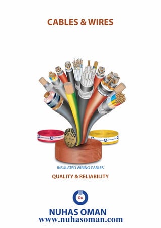


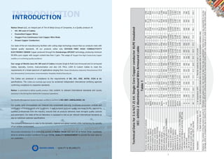


Nuhas Oman LLC, part of the Al Bahja Group, is a manufacturer of high-quality cables, wires, and conductors utilizing oxygen-free copper technology. Their products meet international standards such as BS, IEC, and UL, and undergo rigorous quality control throughout production. The company aims to serve domestic, regional, and global markets while maintaining environmental standards and achieving product excellence through total quality management.