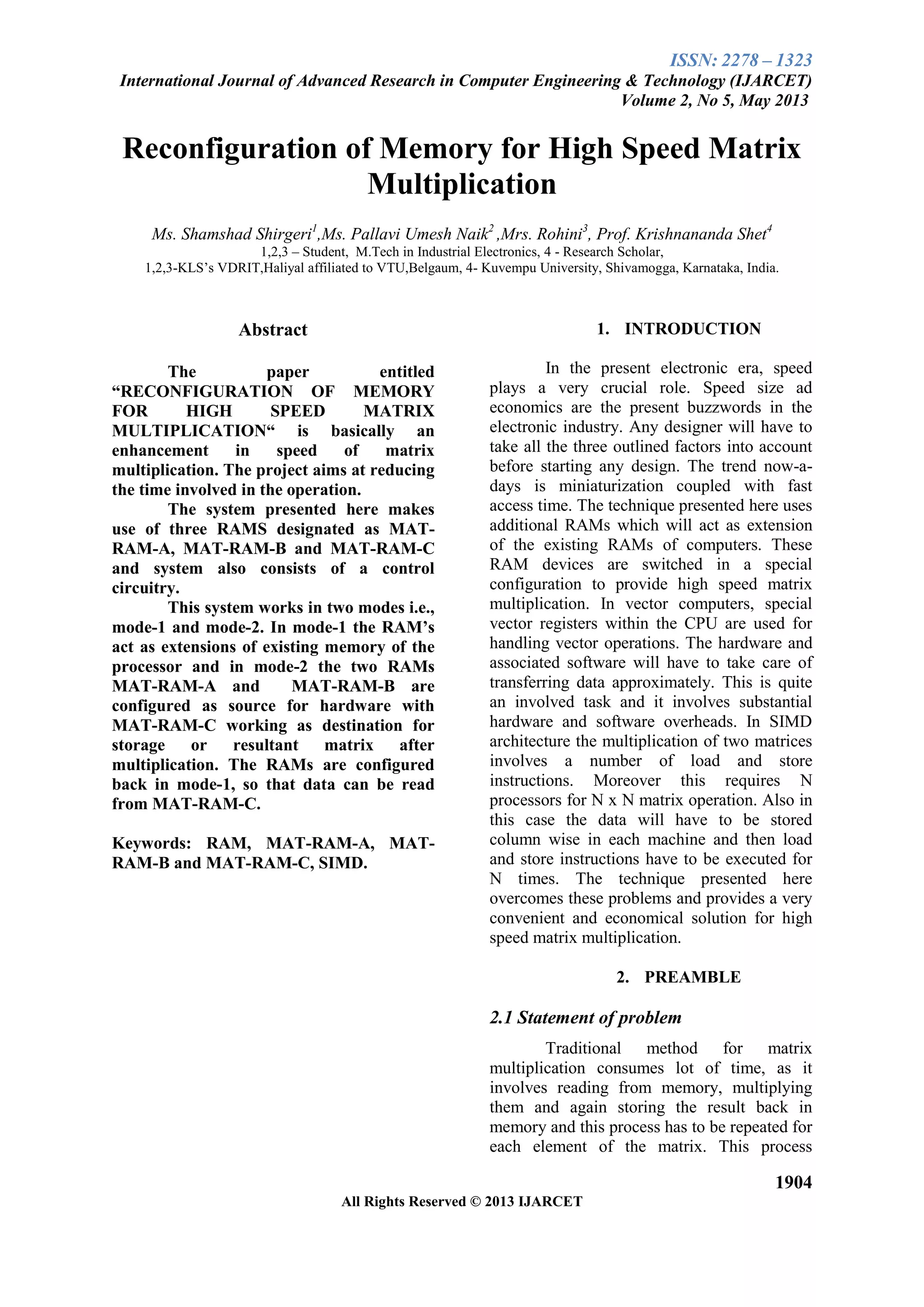
ISSN: 2278 – 1323
International Journal of Advanced Research in Computer Engineering & Technology (IJARCET)
Volume 2, No 5, May 2013
1904
All Rights Reserved © 2013 IJARCET
Reconfiguration of Memory for High Speed Matrix
Multiplication
Ms. Shamshad Shirgeri1
,Ms. Pallavi Umesh Naik2
,Mrs. Rohini3
, Prof. Krishnananda Shet4
1,2,3 – Student, M.Tech in Industrial Electronics, 4 - Research Scholar,
1,2,3-KLS’s VDRIT,Haliyal affiliated to VTU,Belgaum, 4- Kuvempu University, Shivamogga, Karnataka, India.
Abstract
The paper entitled
“RECONFIGURATION OF MEMORY
FOR HIGH SPEED MATRIX
MULTIPLICATION“ is basically an
enhancement in speed of matrix
multiplication. The project aims at reducing
the time involved in the operation.
The system presented here makes
use of three RAMS designated as MAT-
RAM-A, MAT-RAM-B and MAT-RAM-C
and system also consists of a control
circuitry.
This system works in two modes i.e.,
mode-1 and mode-2. In mode-1 the RAM’s
act as extensions of existing memory of the
processor and in mode-2 the two RAMs
MAT-RAM-A and MAT-RAM-B are
configured as source for hardware with
MAT-RAM-C working as destination for
storage or resultant matrix after
multiplication. The RAMs are configured
back in mode-1, so that data can be read
from MAT-RAM-C.
Keywords: RAM, MAT-RAM-A, MAT-
RAM-B and MAT-RAM-C, SIMD.
1. INTRODUCTION
In the present electronic era, speed
plays a very crucial role. Speed size ad
economics are the present buzzwords in the
electronic industry. Any designer will have to
take all the three outlined factors into account
before starting any design. The trend now-a-
days is miniaturization coupled with fast
access time. The technique presented here uses
additional RAMs which will act as extension
of the existing RAMs of computers. These
RAM devices are switched in a special
configuration to provide high speed matrix
multiplication. In vector computers, special
vector registers within the CPU are used for
handling vector operations. The hardware and
associated software will have to take care of
transferring data approximately. This is quite
an involved task and it involves substantial
hardware and software overheads. In SIMD
architecture the multiplication of two matrices
involves a number of load and store
instructions. Moreover this requires N
processors for N x N matrix operation. Also in
this case the data will have to be stored
column wise in each machine and then load
and store instructions have to be executed for
N times. The technique presented here
overcomes these problems and provides a very
convenient and economical solution for high
speed matrix multiplication.
2. PREAMBLE
2.1 Statement of problem
Traditional method for matrix
multiplication consumes lot of time, as it
involves reading from memory, multiplying
them and again storing the result back in
memory and this process has to be repeated for
each element of the matrix. This process
ISSN: 2278 – 1323
International Journal of Advanced Research in Computer Engineering & Technology (IJARCET)
Volume 2, No 5, May 2013
1905
All Rights Reserved © 2013 IJARCET
obviously wastes processors time. Processors
time can be judiciously utilized by the
technique presented here.
2.2 Scope of Study
This system provides a very
convenient and economical solution for high
speed matrix multiplication. The speed is quite
high and is limited only by the access time of
the RAM devices used for this purpose.
2.3 Methodology
 Splitting the design into functional
modules. The complete design to be
implemented to be broken into smaller
modules catering to the different
functions.
 Adding the designed modules to the
library. The design modules are added
to the library so that they can be
accessed whenever necessary. This
method reduces length of coding.
 Interconnecting all the modules to
complete the circuit. The various
modules required for are called from
the library and then are interconnected
as required.
2.4 Limitation of the system
 The speed of the system is limited
only by the access time of the RAMS
used in the circuit.
3. BLOCK DIAGRAM OF
RECONFIGURATION OF
MEMORY FOR HIGH SPEED
MATRIX MULTIPLICATION
Figure1. Block Diagram of
reconfiguration of memory for
high speed matrix multiplication
The system presented here consists of
 Processor
 Switching unit
 External control unit
 RAM’s
This system operates in one of the two
modes in mode-1 these can be used as RAM’s
of the main processor, connected just as an
extension RAM’s of the main processor. In
this mode the necessary control signals of the
RAM’s are connected to the processors data
bus.
In mode-2, these are used for matrix
multiplication process. In this mode the
RAM’s are isolated from the main processor
MATRAM-A and MATRAM-B store the
input data matrix and output of the operation is
stored in MATRAM-C. The necessary control
signals are obtained from the external circuit.
3.1 Switching unit
The switching part consists of two
multiplexers one for transferring data between
RAM and external control unit. The other
multiplexer is used for routing the control
signals to RAM either from the processor or
from an external control unit.
Depending upon the select input
switching unit connect the RAM’s either to the
processor or the external control unit. The
system operates in two modes, the mode of
operation is decided by the input applied to
select pin of switching unit.
Figure2. Switching Unit
ISSN: 2278 – 1323
International Journal of Advanced Research in Computer Engineering & Technology (IJARCET)
Volume 2, No 5, May 2013
1906
All Rights Reserved © 2013 IJARCET
3.2 External control unit
Figure3. External Control Unit
It consists of
 A Multiplier
 An 8 bit parallel adder
 A register
 Three counters
 A clock
3.2.1 Multiplier
Used for the multiplication of the matrix
elements. It takes the inputs from the two
matrices, namely MATRAM-A and
MATRAM-B. It generates the partial product
and this becomes the input for the order block.
3.2.2 8 bit Parallel adder
Used for the summation purpose. It has
two inputs one is partial product from the
multiplier block and the other input is the
previous sum from the register block.
Figure4. 8 bit parallel adder
3.2.3 Register
Used for storing the sum from the
adder block temporarily. Register initially
contains zero. Register gets reset once the
resultant matrix element is generated.
3.2.4 Counters
The counters used here are binary
up counters that generate addresses of
RAMs during Mode-2 operation along
with the addresses, and bi-directional
multiplexers used I the circuit that controls
the mode of operation of the system. The
counter has a register in it, which should
be loaded with the number of elements of
the matrix. The counter counts until the
loaded value, during which the select
signal generated by the counter is at logic
high and hence the system operates I
mode-2, as soon as the count equals the
stored value the select signal becomes low,
now the system is switched back to mode-
1.
Figure5. Counters
3.3 RAM’s
MATRAM-A, MATRAM-B and MATRAM-
C which are present in the system are just an
extension of existing RAM’s of the main
processor during mode-1 and in this mode the
address lines are generated by the processor
and input data are given by the processor
itself. MATRAM-A and MATRAM-B are
configured as source for the hardware.
MATRAM-C works as destination matrix to
store the resultant. During mode-2 their
address lines are generated by the external
circuit. The RAM’s are again configured back
in mode-1, so that data can be read from
MATRAM-C.
ISSN: 2278 – 1323
International Journal of Advanced Research in Computer Engineering & Technology (IJARCET)
Volume 2, No 5, May 2013
1907
All Rights Reserved © 2013 IJARCET
4. MODES OF OPERATION
4.1 Mode-1
In mode-1, the input to the select pin
of external circuit is at logic low. Under this
condition the RAM’s are connected to the
processor. Under this mode, the RAM’s are
connected to the processor and are isolated
from the external circuit. In this mode the
address and control signals for the RAM’s are
obtained from the processor, and processor
data bus is connected to the RAM’s data bus.
Hence reading from or writing into the RAM
is under the control of the processor.
4.2 Mode-2
In the mode-2 the input to the select
pin is high. Under this condition the RAM’s
are connected to the external circuit. The
RAM’s are completely isolated from main
processor. In this mode, the address of the
RAM’s are obtained from the external control
unit, the data buses of RAM-A and RAM-B
are connected to the multiplier input and the
data bus of RAM-C is connected to the output
of the adder.
5. VHDL IMPLEMENTATION
Figure6. Implementation of
Reconfiguration of memory for high speed
matrix multiplication using VHDL.
6. GRAPHICAL COMPARISION
Figure7. Graphical comparison of
Reconfiguration of memory for high speed
matrix multiplication
ISSN: 2278 – 1323
International Journal of Advanced Research in Computer Engineering & Technology (IJARCET)
Volume 2, No 5, May 2013
1908
All Rights Reserved © 2013 IJARCET
7. CONCLUSION
 It provides a much faster and an
economic technique for matrix
multiplication operation.
 The speed in this technique will be
more than ten times faster
compared to Pentium processor.
 Cost involved will be less
compared to that of a vector
machine or a SMID machine.
 The speed of the operation is only
limited by the access time of the
RAM chip used in the circuit.
8. REFERENCES
 P.H.W. Leong, M.P. Leong, O.Y.H.
Cheung, T. Tung, C.M. Kwok, and
K.H. Lee, “Pilchard – A
Reconfigurable Computing Platform
with Memory Interface”.
 Xilinx, “Virtex-E 1.8 V Field
Programmable Gate Arrays”.
 Randall Hyde, "The Art of Assembly
Language Programming".
http://webster.cs.ucr.edu/Page_AoA
Linux/HTML/AoATOC.html
 IEEE international conference on “An
FPGA based floating-point processor
array supporting a high-precision dot
product” by Fritz Mayer.

1904 1908

  • 1.
    ISSN: 2278 –1323 International Journal of Advanced Research in Computer Engineering & Technology (IJARCET) Volume 2, No 5, May 2013 1904 All Rights Reserved © 2013 IJARCET Reconfiguration of Memory for High Speed Matrix Multiplication Ms. Shamshad Shirgeri1 ,Ms. Pallavi Umesh Naik2 ,Mrs. Rohini3 , Prof. Krishnananda Shet4 1,2,3 – Student, M.Tech in Industrial Electronics, 4 - Research Scholar, 1,2,3-KLS’s VDRIT,Haliyal affiliated to VTU,Belgaum, 4- Kuvempu University, Shivamogga, Karnataka, India. Abstract The paper entitled “RECONFIGURATION OF MEMORY FOR HIGH SPEED MATRIX MULTIPLICATION“ is basically an enhancement in speed of matrix multiplication. The project aims at reducing the time involved in the operation. The system presented here makes use of three RAMS designated as MAT- RAM-A, MAT-RAM-B and MAT-RAM-C and system also consists of a control circuitry. This system works in two modes i.e., mode-1 and mode-2. In mode-1 the RAM’s act as extensions of existing memory of the processor and in mode-2 the two RAMs MAT-RAM-A and MAT-RAM-B are configured as source for hardware with MAT-RAM-C working as destination for storage or resultant matrix after multiplication. The RAMs are configured back in mode-1, so that data can be read from MAT-RAM-C. Keywords: RAM, MAT-RAM-A, MAT- RAM-B and MAT-RAM-C, SIMD. 1. INTRODUCTION In the present electronic era, speed plays a very crucial role. Speed size ad economics are the present buzzwords in the electronic industry. Any designer will have to take all the three outlined factors into account before starting any design. The trend now-a- days is miniaturization coupled with fast access time. The technique presented here uses additional RAMs which will act as extension of the existing RAMs of computers. These RAM devices are switched in a special configuration to provide high speed matrix multiplication. In vector computers, special vector registers within the CPU are used for handling vector operations. The hardware and associated software will have to take care of transferring data approximately. This is quite an involved task and it involves substantial hardware and software overheads. In SIMD architecture the multiplication of two matrices involves a number of load and store instructions. Moreover this requires N processors for N x N matrix operation. Also in this case the data will have to be stored column wise in each machine and then load and store instructions have to be executed for N times. The technique presented here overcomes these problems and provides a very convenient and economical solution for high speed matrix multiplication. 2. PREAMBLE 2.1 Statement of problem Traditional method for matrix multiplication consumes lot of time, as it involves reading from memory, multiplying them and again storing the result back in memory and this process has to be repeated for each element of the matrix. This process
  • 2.
    ISSN: 2278 –1323 International Journal of Advanced Research in Computer Engineering & Technology (IJARCET) Volume 2, No 5, May 2013 1905 All Rights Reserved © 2013 IJARCET obviously wastes processors time. Processors time can be judiciously utilized by the technique presented here. 2.2 Scope of Study This system provides a very convenient and economical solution for high speed matrix multiplication. The speed is quite high and is limited only by the access time of the RAM devices used for this purpose. 2.3 Methodology  Splitting the design into functional modules. The complete design to be implemented to be broken into smaller modules catering to the different functions.  Adding the designed modules to the library. The design modules are added to the library so that they can be accessed whenever necessary. This method reduces length of coding.  Interconnecting all the modules to complete the circuit. The various modules required for are called from the library and then are interconnected as required. 2.4 Limitation of the system  The speed of the system is limited only by the access time of the RAMS used in the circuit. 3. BLOCK DIAGRAM OF RECONFIGURATION OF MEMORY FOR HIGH SPEED MATRIX MULTIPLICATION Figure1. Block Diagram of reconfiguration of memory for high speed matrix multiplication The system presented here consists of  Processor  Switching unit  External control unit  RAM’s This system operates in one of the two modes in mode-1 these can be used as RAM’s of the main processor, connected just as an extension RAM’s of the main processor. In this mode the necessary control signals of the RAM’s are connected to the processors data bus. In mode-2, these are used for matrix multiplication process. In this mode the RAM’s are isolated from the main processor MATRAM-A and MATRAM-B store the input data matrix and output of the operation is stored in MATRAM-C. The necessary control signals are obtained from the external circuit. 3.1 Switching unit The switching part consists of two multiplexers one for transferring data between RAM and external control unit. The other multiplexer is used for routing the control signals to RAM either from the processor or from an external control unit. Depending upon the select input switching unit connect the RAM’s either to the processor or the external control unit. The system operates in two modes, the mode of operation is decided by the input applied to select pin of switching unit. Figure2. Switching Unit
  • 3.
    ISSN: 2278 –1323 International Journal of Advanced Research in Computer Engineering & Technology (IJARCET) Volume 2, No 5, May 2013 1906 All Rights Reserved © 2013 IJARCET 3.2 External control unit Figure3. External Control Unit It consists of  A Multiplier  An 8 bit parallel adder  A register  Three counters  A clock 3.2.1 Multiplier Used for the multiplication of the matrix elements. It takes the inputs from the two matrices, namely MATRAM-A and MATRAM-B. It generates the partial product and this becomes the input for the order block. 3.2.2 8 bit Parallel adder Used for the summation purpose. It has two inputs one is partial product from the multiplier block and the other input is the previous sum from the register block. Figure4. 8 bit parallel adder 3.2.3 Register Used for storing the sum from the adder block temporarily. Register initially contains zero. Register gets reset once the resultant matrix element is generated. 3.2.4 Counters The counters used here are binary up counters that generate addresses of RAMs during Mode-2 operation along with the addresses, and bi-directional multiplexers used I the circuit that controls the mode of operation of the system. The counter has a register in it, which should be loaded with the number of elements of the matrix. The counter counts until the loaded value, during which the select signal generated by the counter is at logic high and hence the system operates I mode-2, as soon as the count equals the stored value the select signal becomes low, now the system is switched back to mode- 1. Figure5. Counters 3.3 RAM’s MATRAM-A, MATRAM-B and MATRAM- C which are present in the system are just an extension of existing RAM’s of the main processor during mode-1 and in this mode the address lines are generated by the processor and input data are given by the processor itself. MATRAM-A and MATRAM-B are configured as source for the hardware. MATRAM-C works as destination matrix to store the resultant. During mode-2 their address lines are generated by the external circuit. The RAM’s are again configured back in mode-1, so that data can be read from MATRAM-C.
  • 4.
    ISSN: 2278 –1323 International Journal of Advanced Research in Computer Engineering & Technology (IJARCET) Volume 2, No 5, May 2013 1907 All Rights Reserved © 2013 IJARCET 4. MODES OF OPERATION 4.1 Mode-1 In mode-1, the input to the select pin of external circuit is at logic low. Under this condition the RAM’s are connected to the processor. Under this mode, the RAM’s are connected to the processor and are isolated from the external circuit. In this mode the address and control signals for the RAM’s are obtained from the processor, and processor data bus is connected to the RAM’s data bus. Hence reading from or writing into the RAM is under the control of the processor. 4.2 Mode-2 In the mode-2 the input to the select pin is high. Under this condition the RAM’s are connected to the external circuit. The RAM’s are completely isolated from main processor. In this mode, the address of the RAM’s are obtained from the external control unit, the data buses of RAM-A and RAM-B are connected to the multiplier input and the data bus of RAM-C is connected to the output of the adder. 5. VHDL IMPLEMENTATION Figure6. Implementation of Reconfiguration of memory for high speed matrix multiplication using VHDL. 6. GRAPHICAL COMPARISION Figure7. Graphical comparison of Reconfiguration of memory for high speed matrix multiplication
  • 5.
    ISSN: 2278 –1323 International Journal of Advanced Research in Computer Engineering & Technology (IJARCET) Volume 2, No 5, May 2013 1908 All Rights Reserved © 2013 IJARCET 7. CONCLUSION  It provides a much faster and an economic technique for matrix multiplication operation.  The speed in this technique will be more than ten times faster compared to Pentium processor.  Cost involved will be less compared to that of a vector machine or a SMID machine.  The speed of the operation is only limited by the access time of the RAM chip used in the circuit. 8. REFERENCES  P.H.W. Leong, M.P. Leong, O.Y.H. Cheung, T. Tung, C.M. Kwok, and K.H. Lee, “Pilchard – A Reconfigurable Computing Platform with Memory Interface”.  Xilinx, “Virtex-E 1.8 V Field Programmable Gate Arrays”.  Randall Hyde, "The Art of Assembly Language Programming". http://webster.cs.ucr.edu/Page_AoA Linux/HTML/AoATOC.html  IEEE international conference on “An FPGA based floating-point processor array supporting a high-precision dot product” by Fritz Mayer.