Download to read offline
![18CSL51 – Network Laboratory
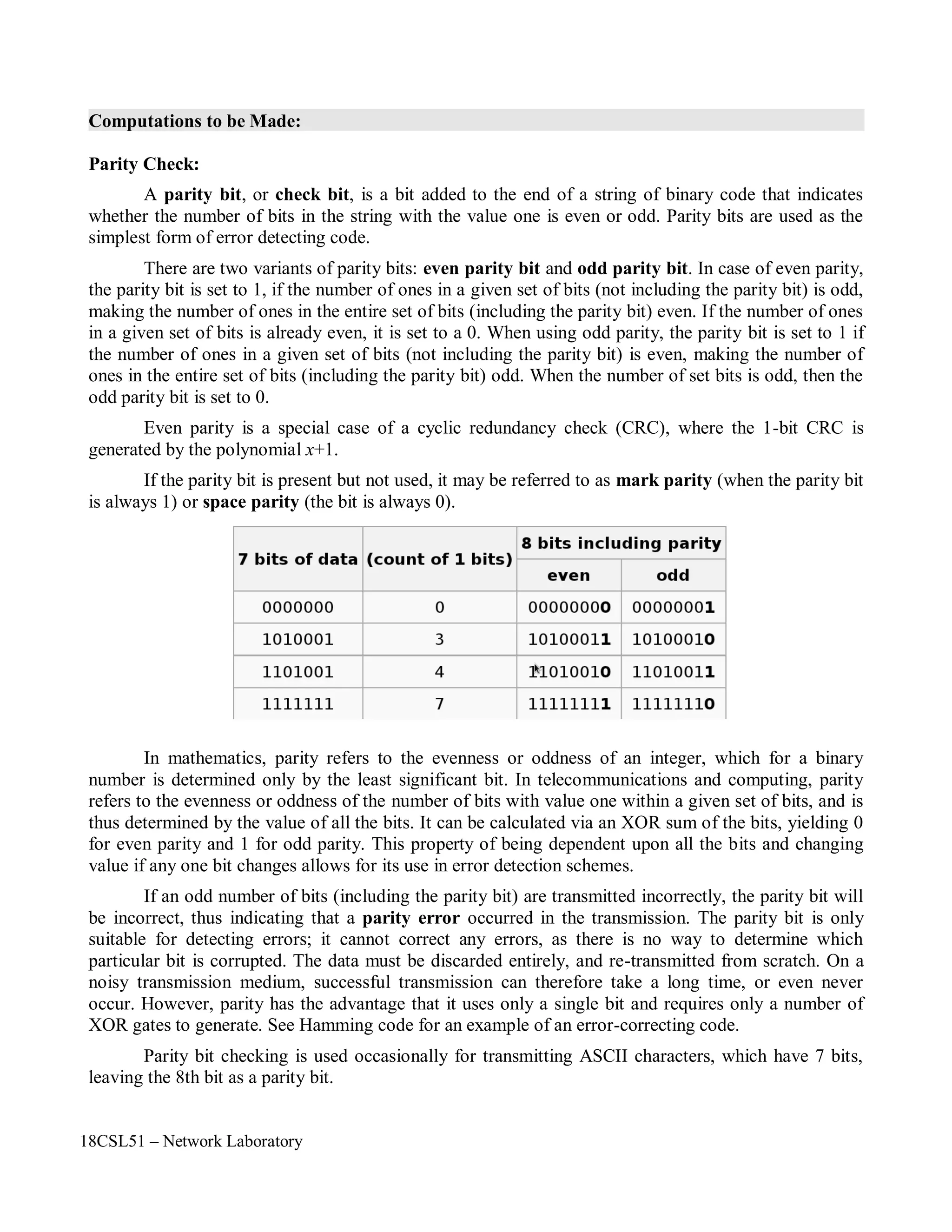
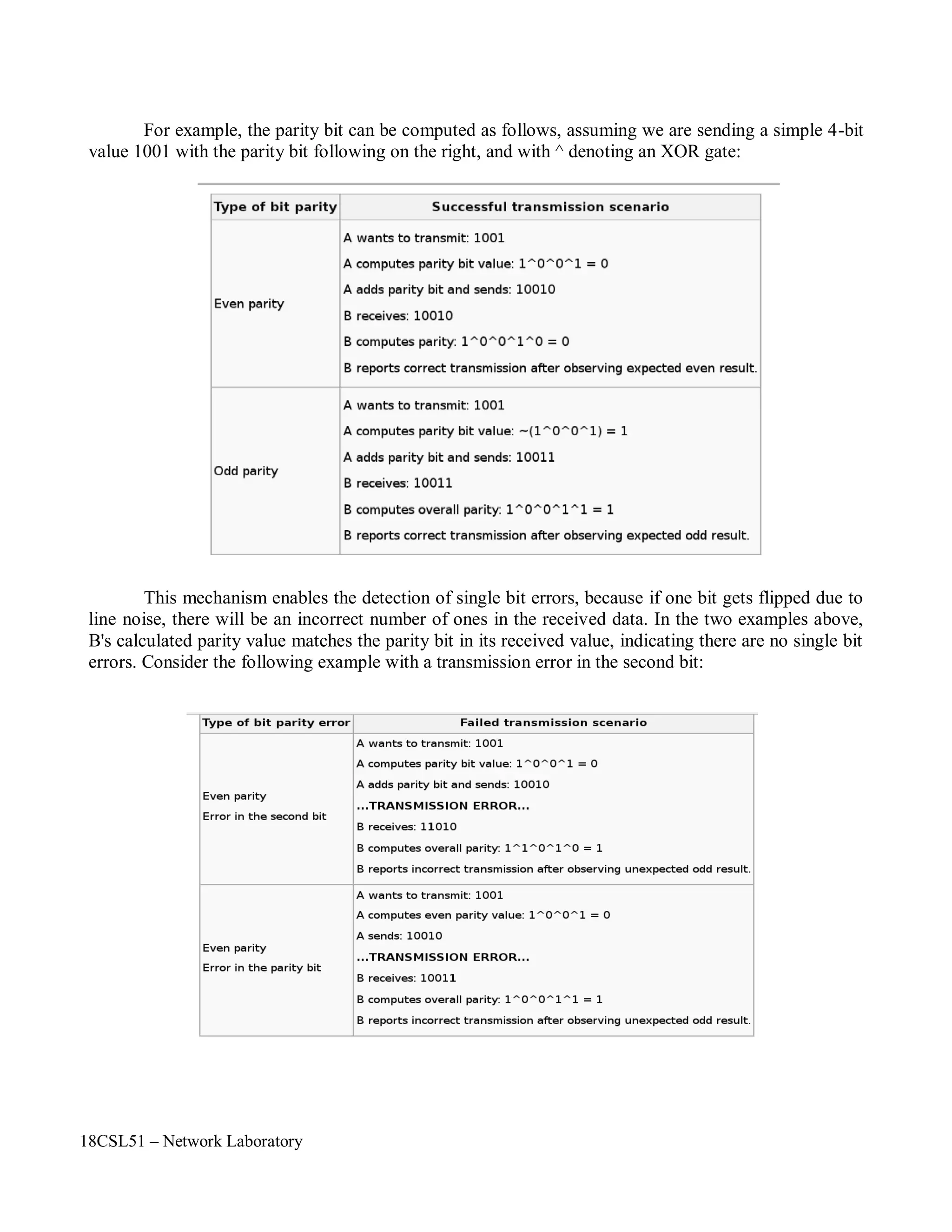
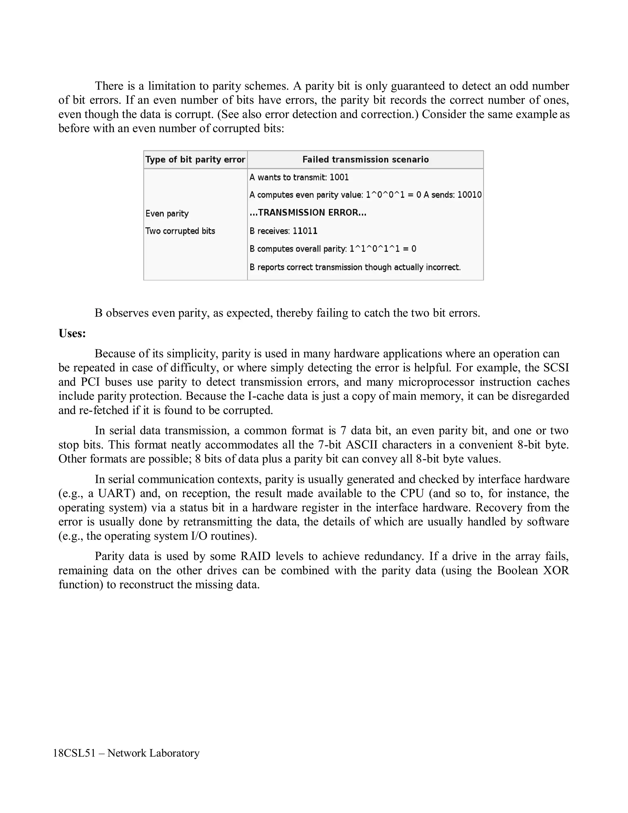
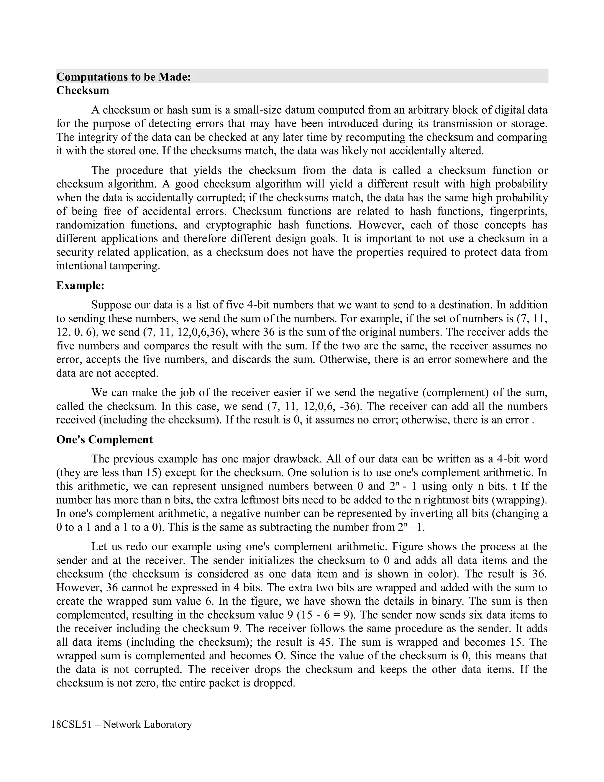
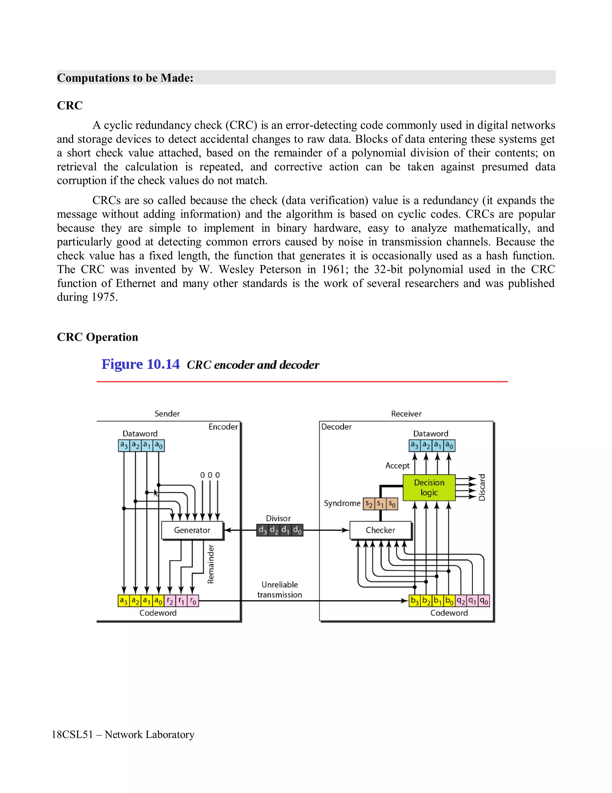
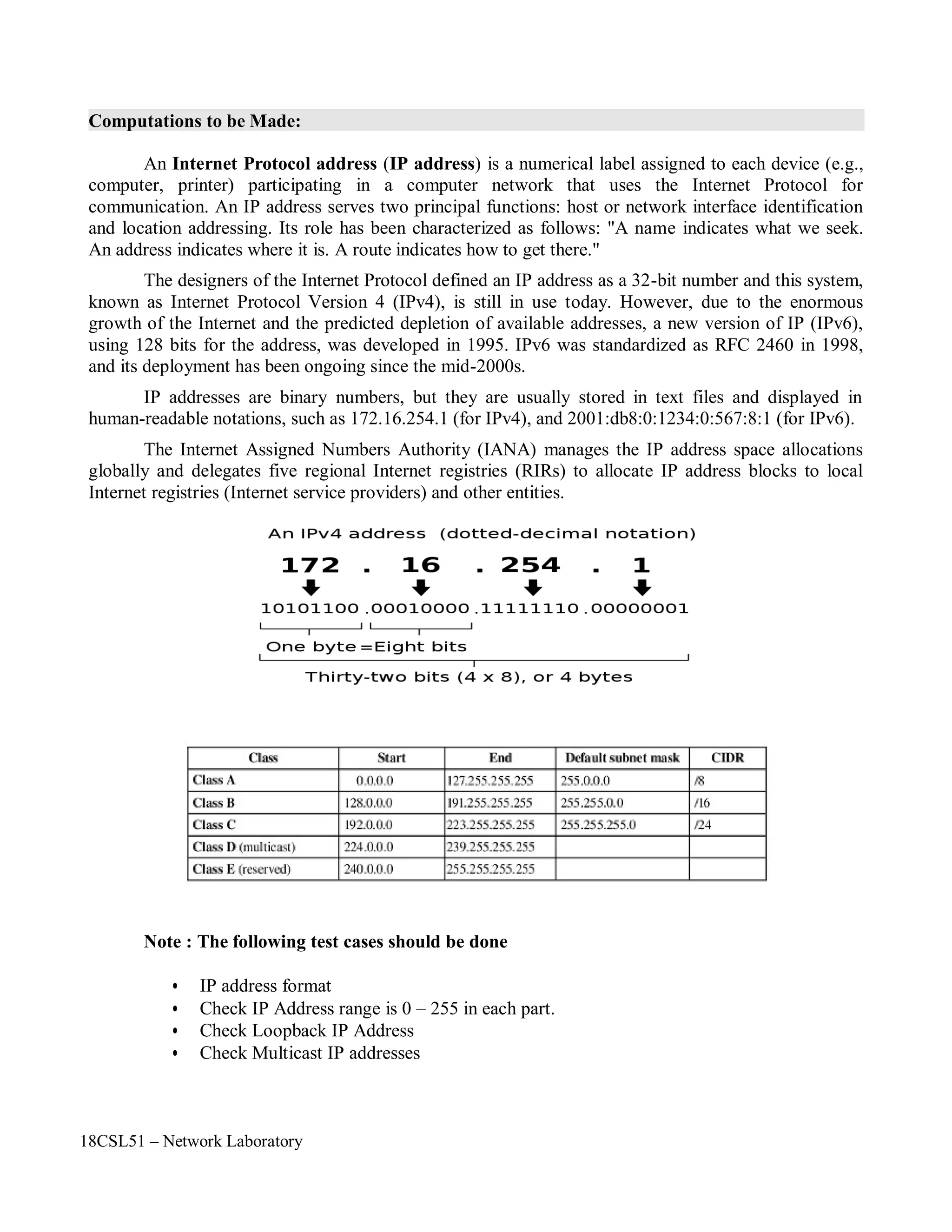
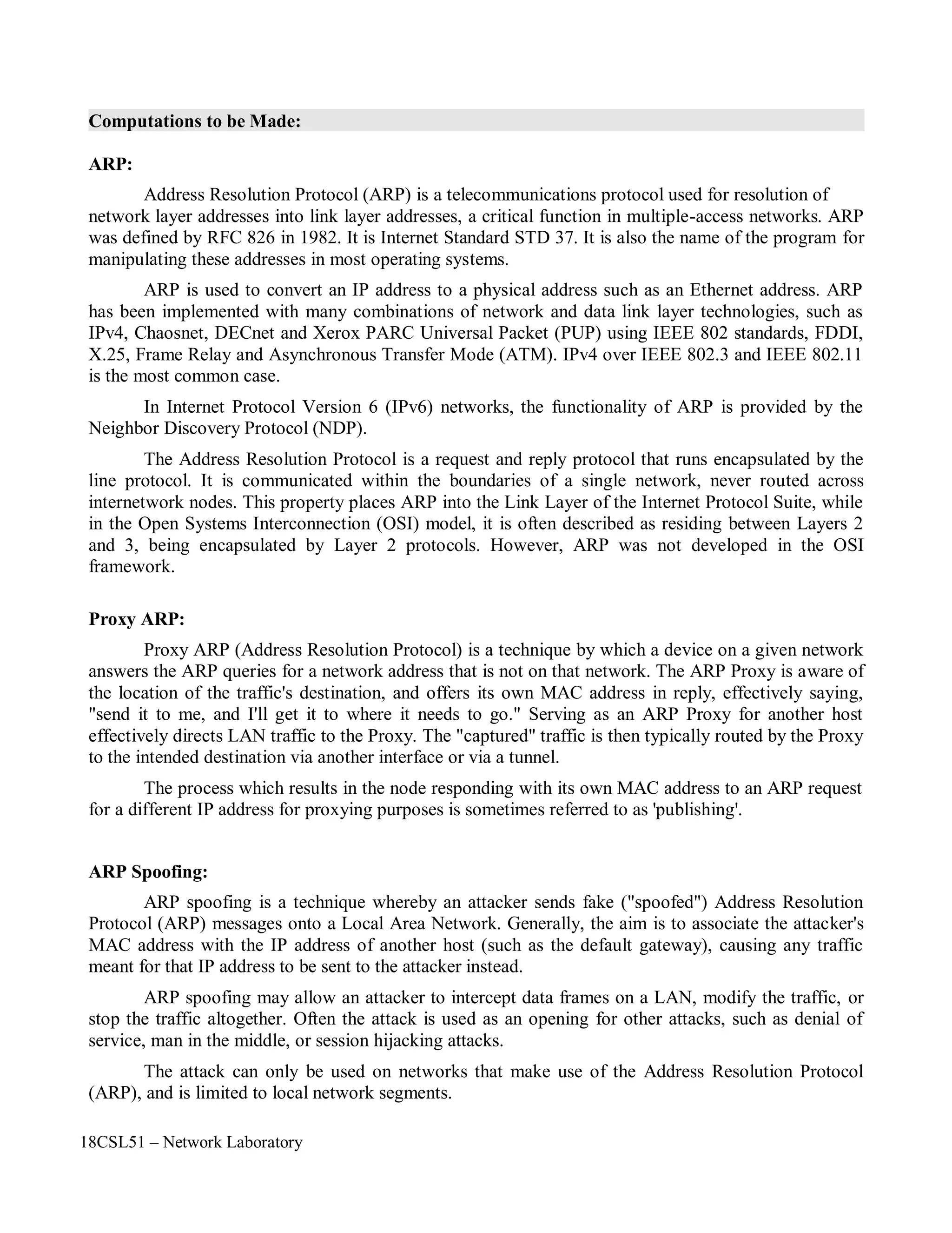
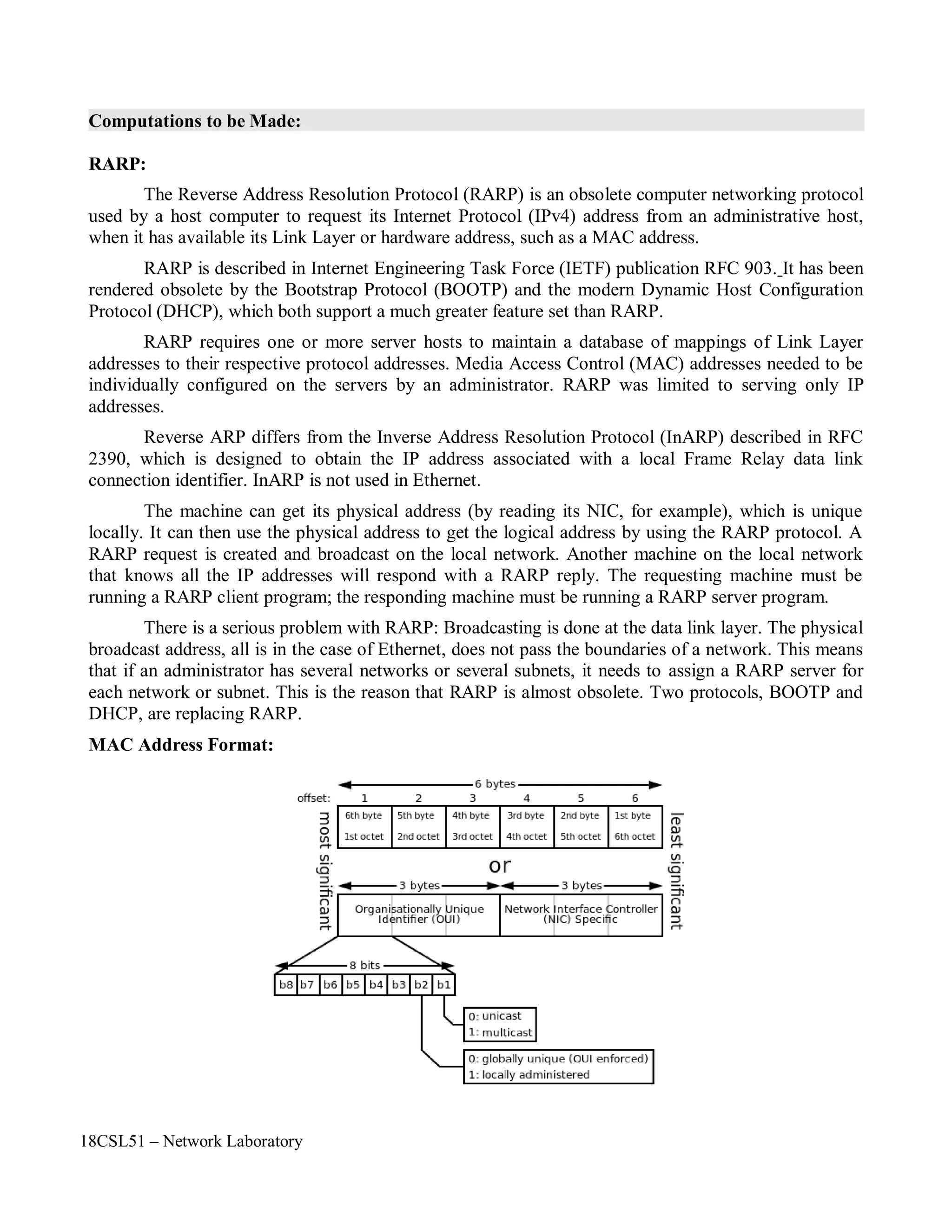
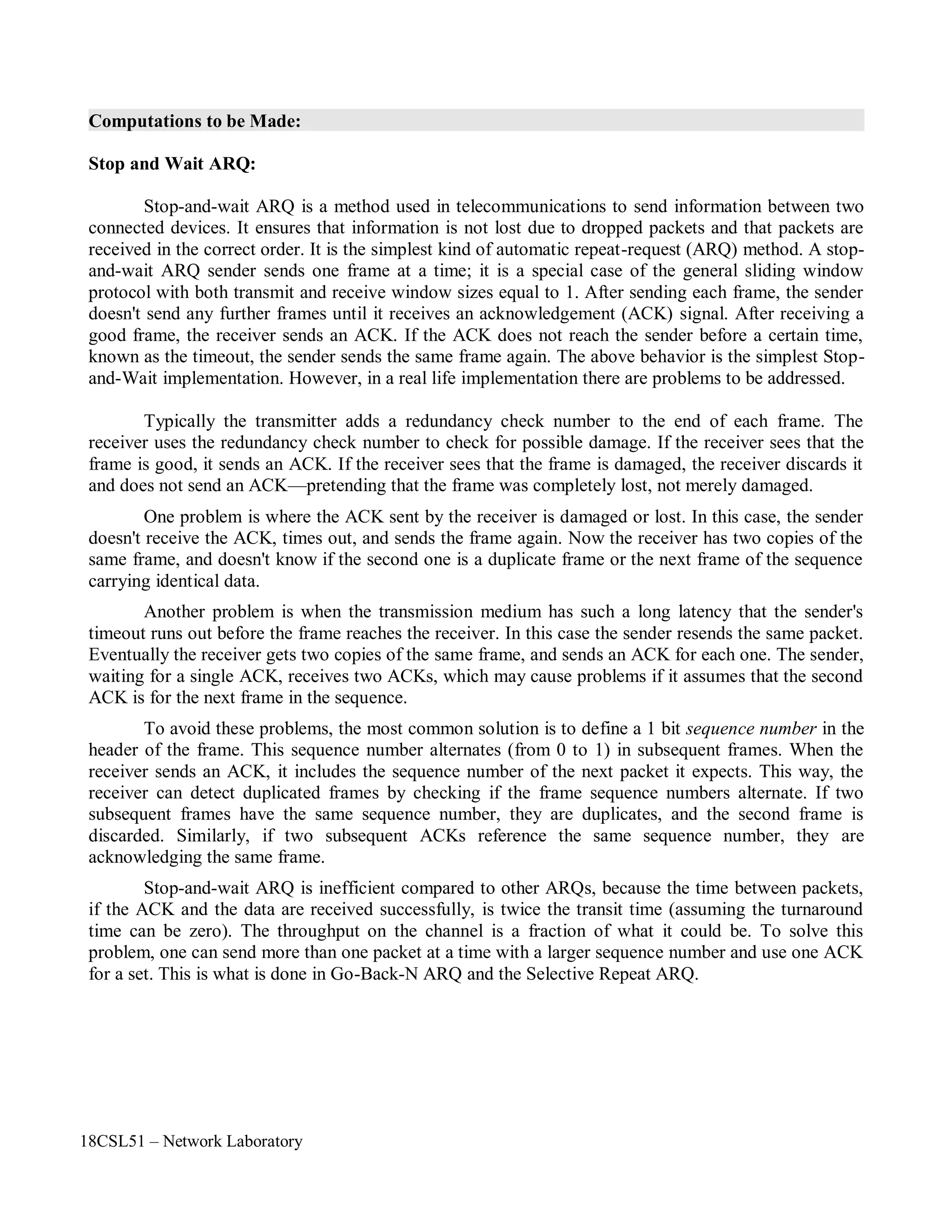
Computations to be Made:
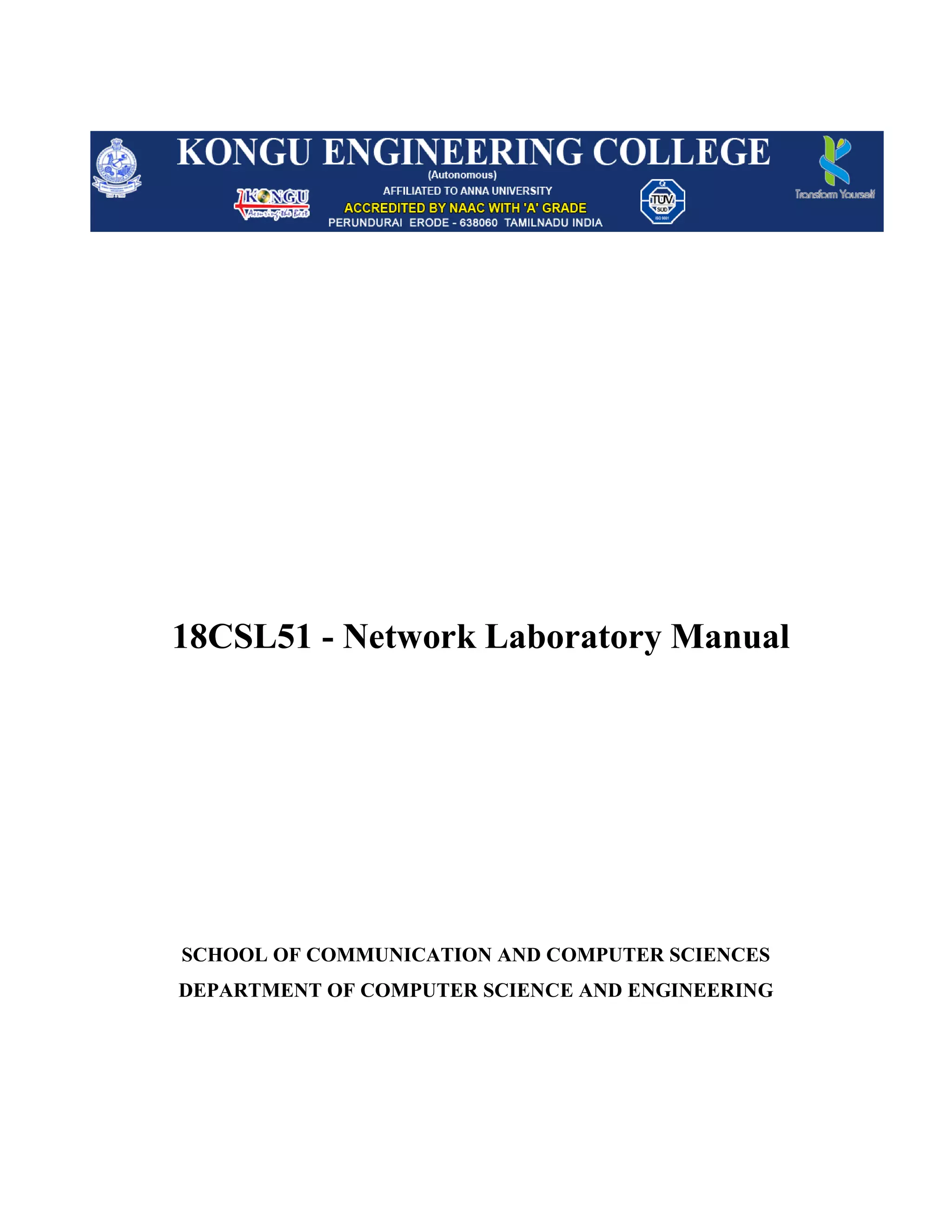
First of all, you need to create a simulator object. This is done with the command
Now open a file for writing that is going to be used for the nam trace data.
The first line opens the file 'out.nam' for writing and gives it the file handle 'nf'. In the second line tell
the simulator object that created above to write all simulation data that is going to be relevant for nam
into this file.
The next step is to add a 'finish' procedure that closes the trace file and starts nam.
The next line tells the simulator object to execute the 'finish' procedure after 5.0 seconds of simulation
time.
You probably understand what this line does just by looking at it. ns provides you with a very simple
way to schedule events with the 'at' command.
The last line finally starts the simulation.
Next to define a very simple topology with two nodes that are connected by a link. The following
two lines define the two nodes. (Note: You have to insert the code in this section before the line
'$ns run', or even better, before the line '$ns at 5.0 "finish"').
set n0 [$ns node]
set n1 [$ns node]
$ns run
$ns at 5.0 "finish"
proc finish {} {
global ns nf
$ns flush-trace
close $nf
exec nam out.nam &
exit 0
}
set nf [open out.nam w]
$ns namtrace-all $nf
set ns [new Simulator]](https://image.slidesharecdn.com/18csl51-networklabmanual-220519112438-6d77913b/75/18CSL51-Network-Lab-Manual-pdf-5-2048.jpg)
![18CSL51 – Network Laboratory
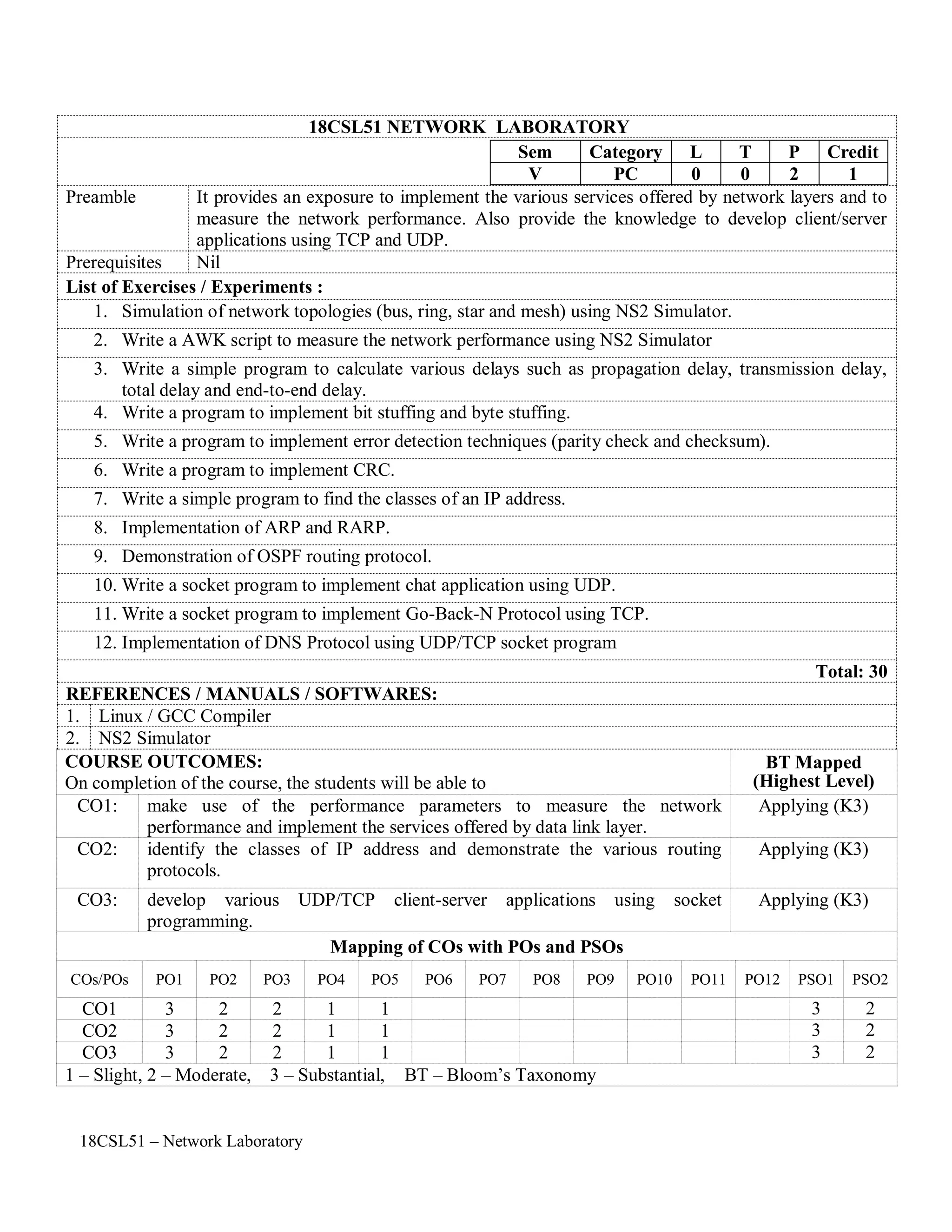
A new node object is created with the command '$ns node'. The above code creates two nodes and
assigns them to the handles 'n0' and 'n1'.
The next line connects the two nodes.
This line tells the simulator object to connect the nodes n0 and n1 with a duplex link with the
bandwidth 1Megabit, a delay of 10ms and a DropTail queue.
The next step is to send some data from node n0 to node n1. In ns, data is always being sent from one
'agent' to another. So the next step is to create an agent object that sends data from node n0, and another
agent object that receives the data on node n1.
These lines create a UDP agent and attach it to the node n0, then attach a CBR traffic generatot to the
UDP agent. CBR stands for 'constant bit rate'. Line 7 and 8 should be self-explaining. The packetSize is
being set to 500 bytes and a packet will be sent every 0.005 seconds (i.e. 200 packets per second).
The next lines create a Null agent which acts as traffic sink and attach it to node n1.
Now the two agents have to be connected with each other.
And now you have to tell the CBR agent when to send data and when to stop sending. Note: It's
probably best to put the following lines just before the line '$ns at 5.0 "finish"'.
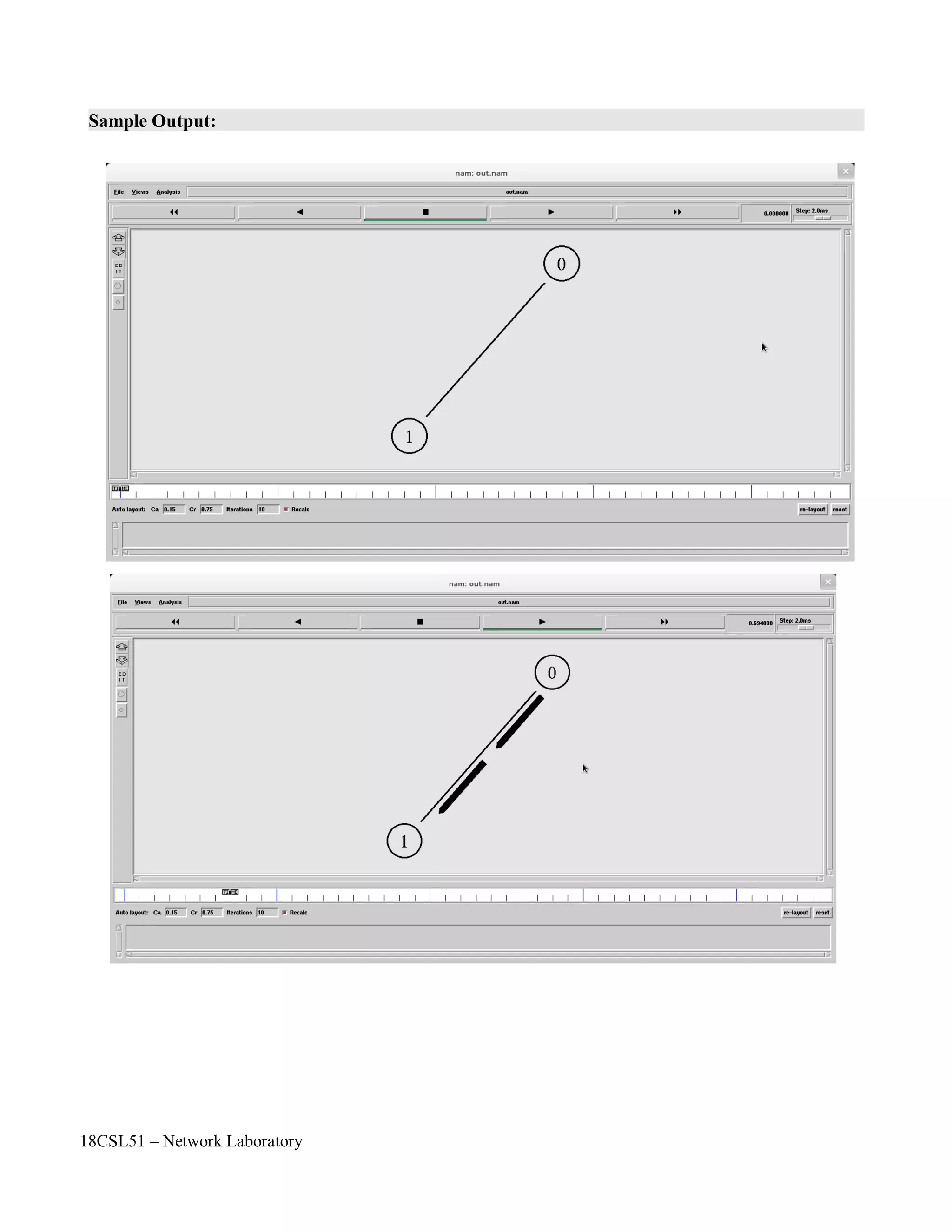
Now you can save the file and start the simulation again. When you click on the 'play' button in the
nam window, you will see that after 0.5 simulation seconds, node 0 starts sending data packets to node
1. You might want to slow nam down then with the 'Step' slider.
$ns at 0.5 "$cbr0 start"
$ns at 4.5 "$cbr0 stop"
$ns connect $udp0 $null0
set null0 [new Agent/Null]
$ns attach-agent $n1 $null0
#Create a UDP agent and attach it to node n0
set udp0 [new Agent/UDP]
$ns attach-agent $n0 $udp0
# Create a CBR traffic source and attach it to udp0
set cbr0 [new Application/Traffic/CBR]
$cbr0 set packetSize_ 500
$cbr0 set interval_ 0.005
$cbr0 attach-agent $udp0
$ns duplex-link $n0 $n1 1Mb 10ms DropTail](https://image.slidesharecdn.com/18csl51-networklabmanual-220519112438-6d77913b/75/18CSL51-Network-Lab-Manual-pdf-6-2048.jpg)
![18CSL51 – Network Laboratory
Program:
#Create a simulator object
set ns [new Simulator]
#Open the nam trace file
set nf [open out.nam w]
$ns namtrace-all $nf
#Define a 'finish' procedure
proc finish {} {
global ns nf
$ns flush-trace
#Close the trace file
close $nf
#Execute nam on the trace file
exec nam out.nam &
exit 0
}
#Create two nodes
set n0 [$ns node]
set n1 [$ns node]
#Create a duplex link between the nodes
$ns duplex-link $n0 $n1 1Mb 10ms DropTail
#Create a UDP agent and attach it to node n0
set udp0 [new Agent/UDP]
$ns attach-agent $n0 $udp0
# Create a CBR traffic source and attach it to udp0
set cbr0 [new Application/Traffic/CBR]
$cbr0 set packetSize_ 500
$cbr0 set interval_ 0.005
$cbr0 attach-agent $udp0
#Create a Null agent (a traffic sink) and attach it to node n1
set null0 [new Agent/Null]
$ns attach-agent $n1 $null0
#Connect the traffic source with the traffic sink
$ns connect $udp0 $null0
#Schedule events for the CBR agent
$ns at 0.5 "$cbr0 start"
$ns at 4.5 "$cbr0 stop"
#Call the finish procedure after 5 seconds of simulation time
$ns at 5.0 "finish"
#Run the simulation
$ns run](https://image.slidesharecdn.com/18csl51-networklabmanual-220519112438-6d77913b/75/18CSL51-Network-Lab-Manual-pdf-8-2048.jpg)
![18CSL51 – Network Laboratory
Computations to be Made:
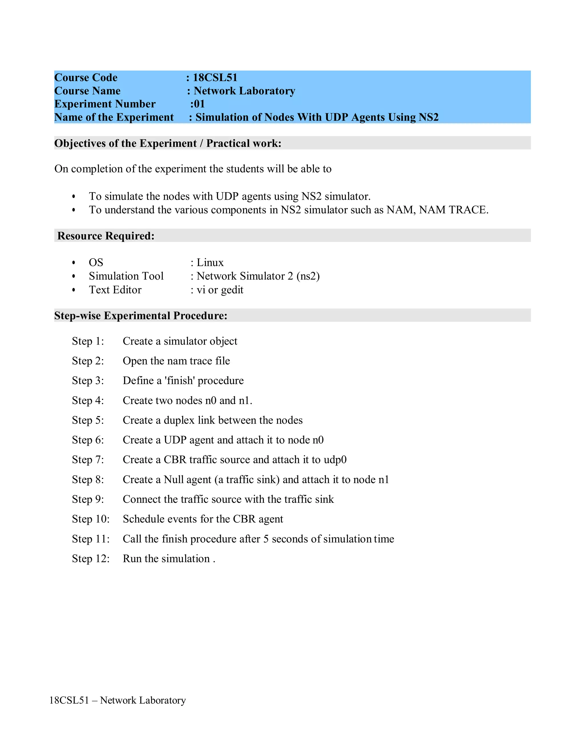
As always, the first step is to define the topology. You should create a file 'star.tcl'. You will
always have to create a simulator object, you will always have to start the simulation with the
same command, and if you want to run nam automatically, you will always have to open a trace
file, initialize it, and define a procedure which closes it and starts nam.
Now insert the following lines into the code to create four nodes.
The following piece of Tcl code creates three duplex links between the nodes.
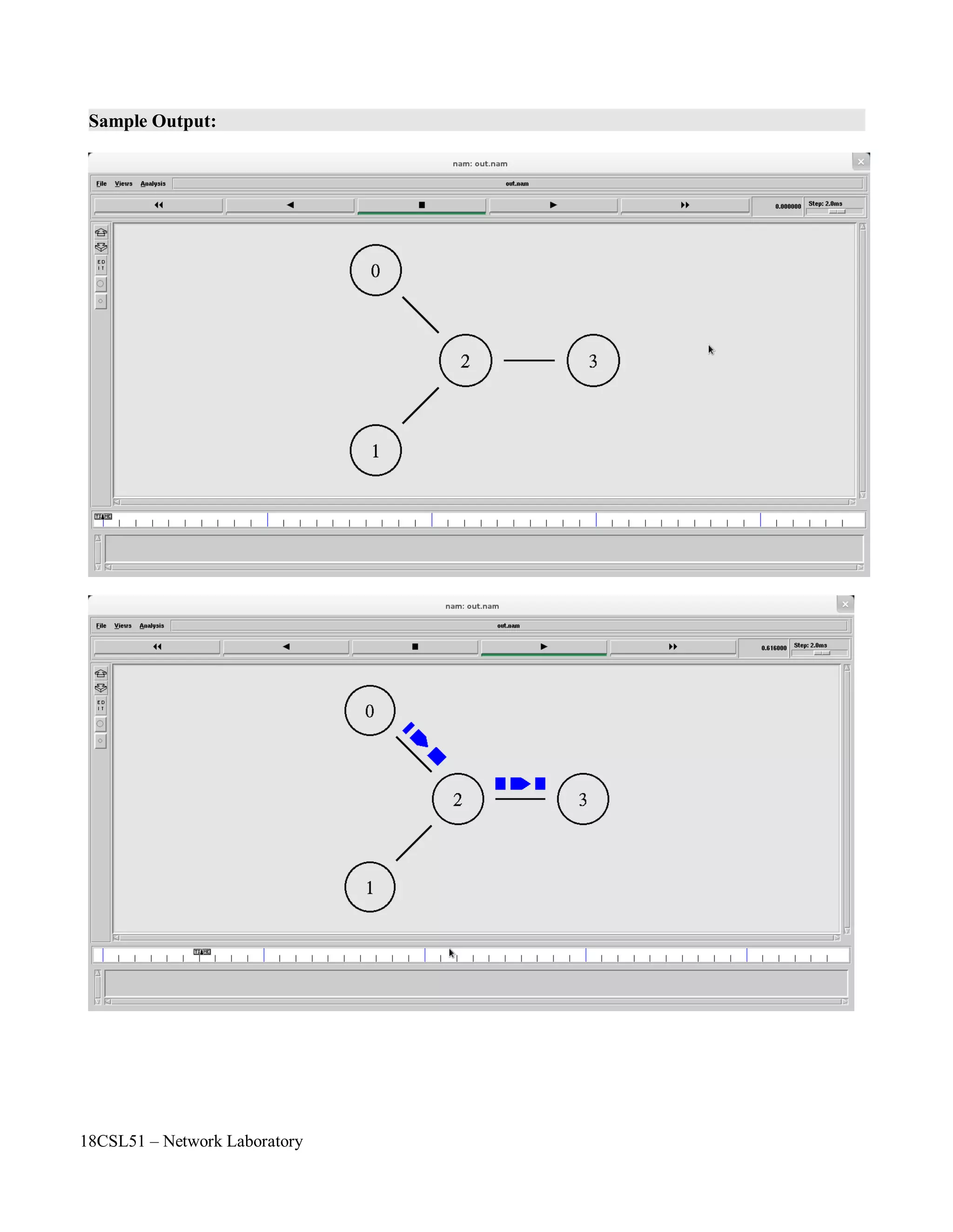
You can save and start the script now. You might notice that the topology looks a bit awkward in nam.
You can hit the 're-layout' button to make it look better, but it would be nice to have some more control
over the layout. Add the next three lines to your Tcl script and start it again.
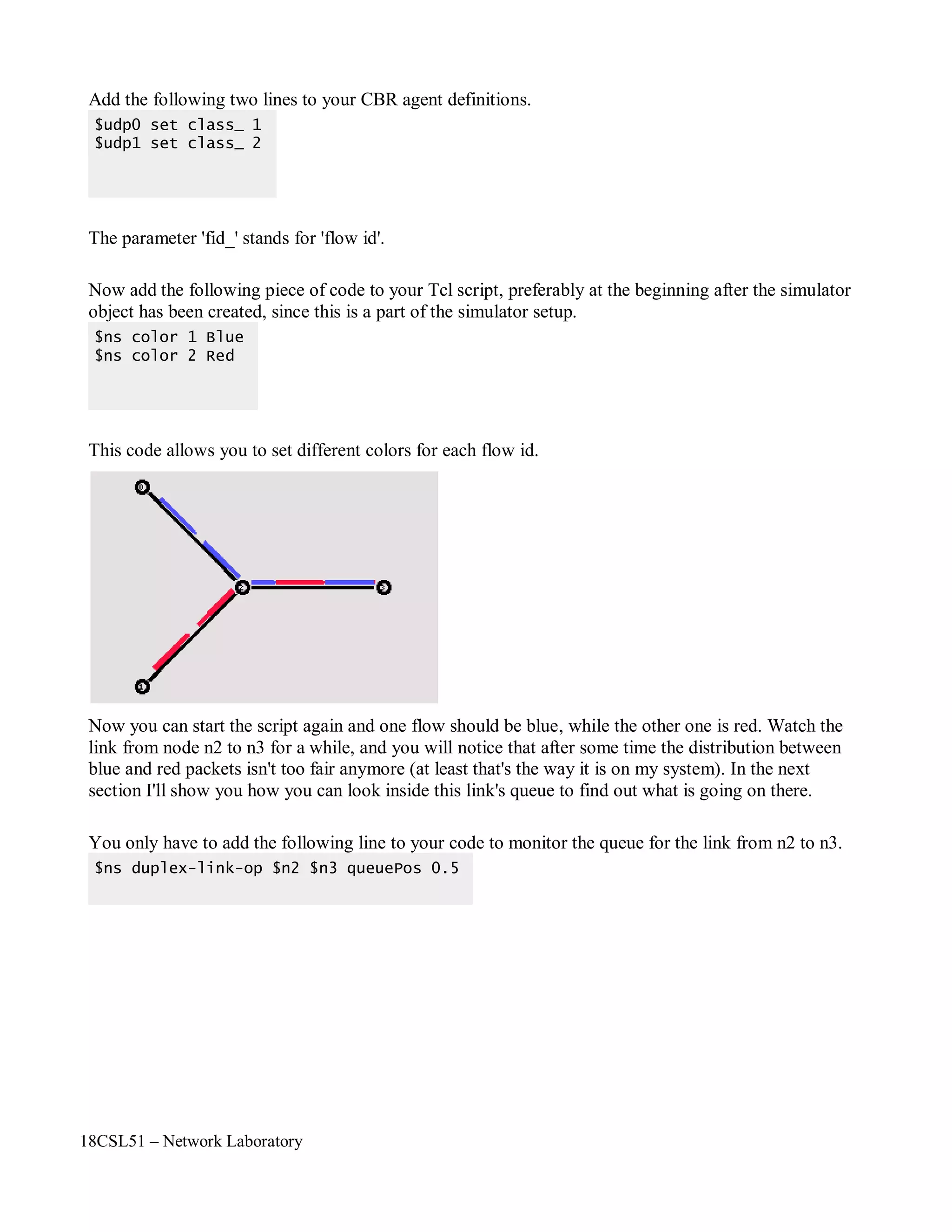
You will probably understand what this code does when you look at the topology in the nam window
now. It should look like the picture below.
Note that the autolayout related parts of nam are gone, since now you have taken the layout into your
own hands. The options for the orientation of a link are right, left, up, down and combinations of these
orientations. You can experiment with these settings later, but for now please leave the topology the
way it is.
$ns duplex-link-op $n0 $n2 orient right-down
$ns duplex-link-op $n1 $n2 orient right-up
$ns duplex-link-op $n2 $n3 orient right
$ns duplex-link $n0 $n2 1Mb 10ms DropTail
$ns duplex-link $n1 $n2 1Mb 10ms DropTail
$ns duplex-link $n3 $n2 1Mb 10ms DropTail
set n0 [$ns node]
set n1 [$ns node]
set n2 [$ns node]
set n3 [$ns node]](https://image.slidesharecdn.com/18csl51-networklabmanual-220519112438-6d77913b/75/18CSL51-Network-Lab-Manual-pdf-11-2048.jpg)
![18CSL51 – Network Laboratory
Now create two UDP agents with CBR traffic sources and attach them to the nodes n0 and n1.
Then create a Null agent and attach it to node n3.
The two CBR agents have to be connected to the Null agent.
We want the first CBR agent to start sending at 0.5 seconds and to stop at 4.5 seconds while the second
CBR agent starts at 1.0 seconds and stops at 4.0 seconds.
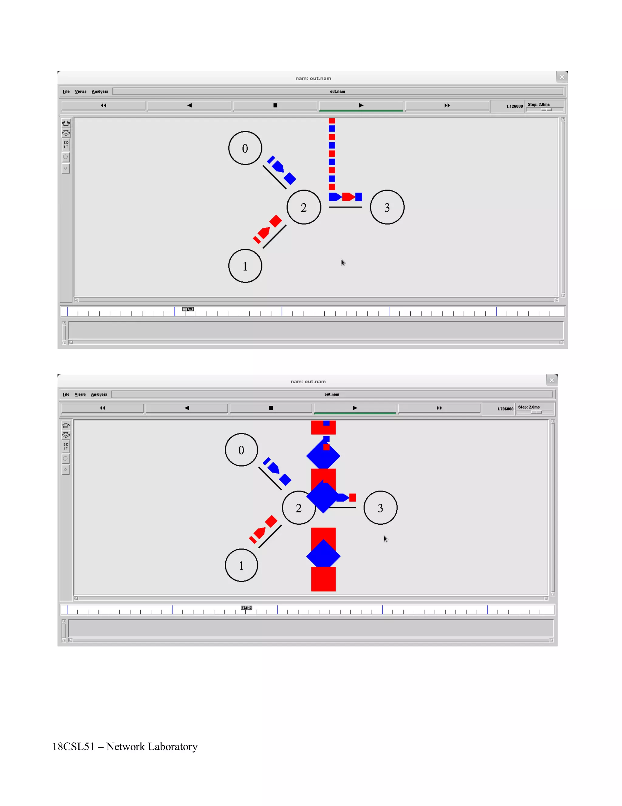
When you start the script now with 'ns star.tcl', you will notice that there is more traffic on the links
from n0 to n2 and n1 to n2 than the link from n2 to n3 can carry. A simple calculation confirms this:
We are sending 200 packets per second on each of the first two links and the packet size is 500 bytes.
This results in a bandwidth of 0.8 megabits per second for the links from n0 to n2 and from n1 to n2.
That's a total bandwidth of 1.6Mb/s, but the link between n2 and n3 only has a capacity of 1Mb/s, so
obviously some packets are being discarded. But which ones? Both flows are black, so the only way to
find out what is happening to the packets is to monitor them in nam by clicking on them. In the next
two sections I'm going to show you how to distinguish between different flows and how to see what is
actually going on in the queue at the link from n2 to n3.
$ns at 0.5 "$cbr0 start"
$ns at 1.0 "$cbr1 start"
$ns at 4.0 "$cbr1 stop"
$ns at 4.5 "$cbr0 stop"
$ns connect $udp0 $null0
$ns connect $udp1 $null0
#Create a UDP agent and attach it to node n0
set udp0 [new Agent/UDP]
$ns attach-agent $n0 $udp0
# Create a CBR traffic source and attach it to udp0
set cbr0 [new Application/Traffic/CBR]
$cbr0 set packetSize_ 500
$cbr0 set interval_ 0.005
$cbr0 attach-agent $udp0
#Create a UDP agent and attach it to node n1
set udp1 [new Agent/UDP]
$ns attach-agent $n1 $udp1
# Create a CBR traffic source and attach it to udp1
set cbr1 [new Application/Traffic/CBR]
$cbr1 set packetSize_ 500
$cbr1 set interval_ 0.005
$cbr1 attach-agent $udp1
set null0 [new Agent/Null]
$ns attach-agent $n3 $null0](https://image.slidesharecdn.com/18csl51-networklabmanual-220519112438-6d77913b/75/18CSL51-Network-Lab-Manual-pdf-12-2048.jpg)

![18CSL51 – Network Laboratory
Formation of Bus Topology
#Creating five nodes
set node1 [$ns node]
set node2 [$ns node]
set node3 [$ns node]
set node4 [$ns node]
set node5 [$ns node]
#Creating Lan connection between the nodes
set lan0 [$ns newLan “$node1 $node2$node3 $node4 $node5” 0.7Mb 20ms LL Queue/FQ MAC/Csma/C
d Channel]
#Creating a TCP agent and attaching it to node 1
set tcp0 [new Agent/TCP]
$tcp0 set class_ 1
$ns attach-agent $node1 $tcp0
#Creating a TCP Sink agent for TCP and attaching it to node 3
set sink0 [new Agent/TCPSink]
$ns attach-agent $node3 $sink0
#Connecting the traffic sources with the traffic sink
$ns connect $tcp0 $sink0
# Creating a CBR traffic source and attach it to tcp0
set cbr0 [new Application/Traffic/CBR]
$cbr0 set packetSize_ 500
$ cbr0 set interval_ 0.05
$cbr0 attach-agent $tcp0
#Schedule events for the CBR agents
$ns at 0.5 “$cbr0 start time”
$ ns at 5.5 “$cbr0 stop time”
#Here we call the finish procedure after 10 seconds of simulation time
$ns at 10.0 “End”
#Finally run the simulation
$ns run](https://image.slidesharecdn.com/18csl51-networklabmanual-220519112438-6d77913b/75/18CSL51-Network-Lab-Manual-pdf-15-2048.jpg)
![18CSL51 – Network Laboratory
Formation of Ring Topology
#Creating six nodes
set node1 [$ns node]
set node2 [$ns node]
set node3 [$ns node]
set node4 [$ns node]
set node5 [$ns node]
set node6 [$ns node]
#Creating links between the nodes
$ns duplex-link $node1 $node2 1Mb 15ms FQ
$ns duplex-link $node2 $node3 1Mb 15ms FQ
$ns duplex-link $node3 $node4 1Mb 15ms FQ
$ns duplex-link $node4 $node5 1Mb 15ms FQ
$ns duplex-link $node5 $node6 1Mb 15ms FQ
$ns duplex-link $node6 $node1 1Mb 15ms FQ”Forms Ring Topology”
#Creating a TCP agent and attaching it to node 1
set tcp0 [new Agent/TCP]
$tcp0 set class_ 1
$ns attach-agent $node1 $tcp0
#Creating a TCP Sink agent for TCP and attaching it to node 3
set sink0 [new Agent/TCPSink]
$ns attach-agent $node3 $sink0
#Connecting the traffic sources with the traffic sink
$ns connect $tcp0 $sink0
# Creating a CBR traffic source and attach it to tcp0
set cbr0 [new Application/Traffic/CBR]
$cbr0 set packetSize_ 500
$cbr0 set interval_ 0.05
$cbr0 attach-agent $tcp0
#Schedule events for the CBR agents
$ns at 0.5 “$cbr0 start time”
$ns at 5.5 “$cbr0 stop time”
#Here we call the finish procedure after 10 seconds of simulation time
$ns at 10.0 “End”
#Finally run the simulation
$ns run](https://image.slidesharecdn.com/18csl51-networklabmanual-220519112438-6d77913b/75/18CSL51-Network-Lab-Manual-pdf-16-2048.jpg)
![18CSL51 – Network Laboratory
Formation of Mesh Topology
#Creating four nodes
set node1 [$ns node]
set node2 [$ns node]
set node3 [$ns node]
set node4 [$ns node]
#Creating links between the nodes
$ns duplex-link $node1 $node2 1Mb 20ms FQ
$ns duplex-link $node1 $node3 1Mb 20ms FQ
$ns duplex-link $node1 $node4 1Mb 20ms FQ
$ns duplex-link $node2 $node3 1Mb 20ms FQ
$ns duplex-link $node2 $node4 1Mb 20ms FQ
$ns duplex-link $node3 $node4 1Mb 20ms FQ“Forms Mesh Topology”
#Creating a TCP agent and attaching it to node 1
set tcp0 [new Agent/TCP]
$tcp0 set class_ 1
$ns attach-agent $node1 $tcp0
#Creating a TCP Sink agent for TCP and attaching it to node 3
set sink0 [new Agent/TCPSink]
$ns attach-agent $node3 $sink0
#Connecting the traffic sources with the traffic sink
$ns connect $tcp0 $sink0
# Creating a CBR traffic source and attach it to tcp0
set cbr0 [new Application/Traffic/CBR]
$cbr0 set packetSize_ 500
$cbr0 set interval_ 0.05
$cbr0 attach-agent $tcp0
#Schedule events for the CBR agents
$ns at 0.5 “$cbr0 start time”
$ns at 5.5 “$cbr0 stop time”
#Here we call the finish procedure after 10 seconds of simulation time
$ns at 10.0 “End”
#Finally run the simulation
$ns run](https://image.slidesharecdn.com/18csl51-networklabmanual-220519112438-6d77913b/75/18CSL51-Network-Lab-Manual-pdf-17-2048.jpg)

![18CSL51 – Network Laboratory
Program:
#Create a simulator object
set ns [new Simulator]
#Define different colors for data flows
$ns color 1 Blue
$ns color 2 Red
#Open the nam trace file
set nf [open out.nam w]
$ns namtrace-all $nf
#Define a 'finish' procedure
proc finish {} {
global ns nf
$ns flush-trace
#Close the trace file
close $nf
#Execute nam on the trace file
exec nam out.nam &
exit 0
}
#Create four nodes
set n0 [$ns node]
set n1 [$ns node]
set n2 [$ns node]
set n3 [$ns node]
#Create links between the nodes
$ns duplex-link $n0 $n2 1Mb 10ms DropTail
$ns duplex-link $n1 $n2 1Mb 10ms DropTail
$ns duplex-link $n3 $n2 1Mb 10ms SFQ
$ns duplex-link-op $n0 $n2 orient right-down
$ns duplex-link-op $n1 $n2 orient right-up
$ns duplex-link-op $n2 $n3 orient right
#Monitor the queue for the link between node 2 and node 3
$ns duplex-link-op $n2 $n3 queuePos 0.5
#Create a UDP agent and attach it to node n0
set udp0 [new Agent/UDP]
$udp0 set class_ 1
$ns attach-agent $n0 $udp0](https://image.slidesharecdn.com/18csl51-networklabmanual-220519112438-6d77913b/75/18CSL51-Network-Lab-Manual-pdf-19-2048.jpg)
![18CSL51 – Network Laboratory
# Create a CBR traffic source and attach it to udp0
set cbr0 [new Application/Traffic/CBR]
$cbr0 set packetSize_ 500
$cbr0 set interval_ 0.005
$cbr0 attach-agent $udp0
#Create a UDP agent and attach it to node n1
set udp1 [new Agent/UDP]
$udp1 set class_ 2
$ns attach-agent $n1 $udp1
# Create a CBR traffic source and attach it to udp1
set cbr1 [new Application/Traffic/CBR]
$cbr1 set packetSize_ 500
$cbr1 set interval_ 0.005
$cbr1 attach-agent $udp1
#Create a Null agent (a traffic sink) and attach it to node n3
set null0 [new Agent/Null]
$ns attach-agent $n3 $null0
#Connect the traffic sources with the traffic sink
$ns connect $udp0 $null0
$ns connect $udp1 $null0
#Schedule events for the CBR agents
$ns at 0.5 "$cbr0 start"
$ns at 1.0 "$cbr1 start"
$ns at 4.0 "$cbr1 stop"
$ns at 4.5 "$cbr0 stop"
#Call the finish procedure after 5 seconds of simulation time
$ns at 5.0 "finish"
#Run the simulation
$ns run](https://image.slidesharecdn.com/18csl51-networklabmanual-220519112438-6d77913b/75/18CSL51-Network-Lab-Manual-pdf-20-2048.jpg)
![18CSL51 – Network Laboratory
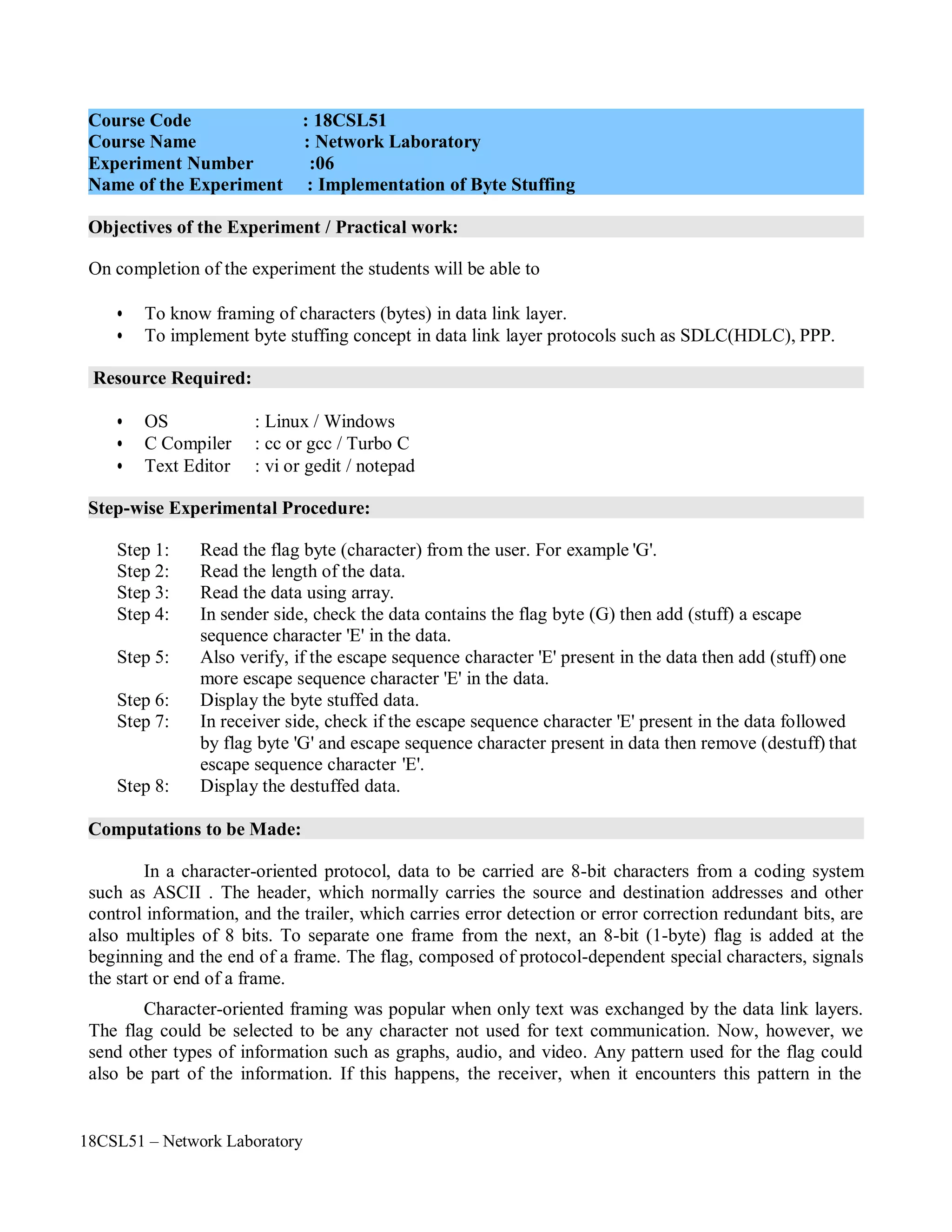
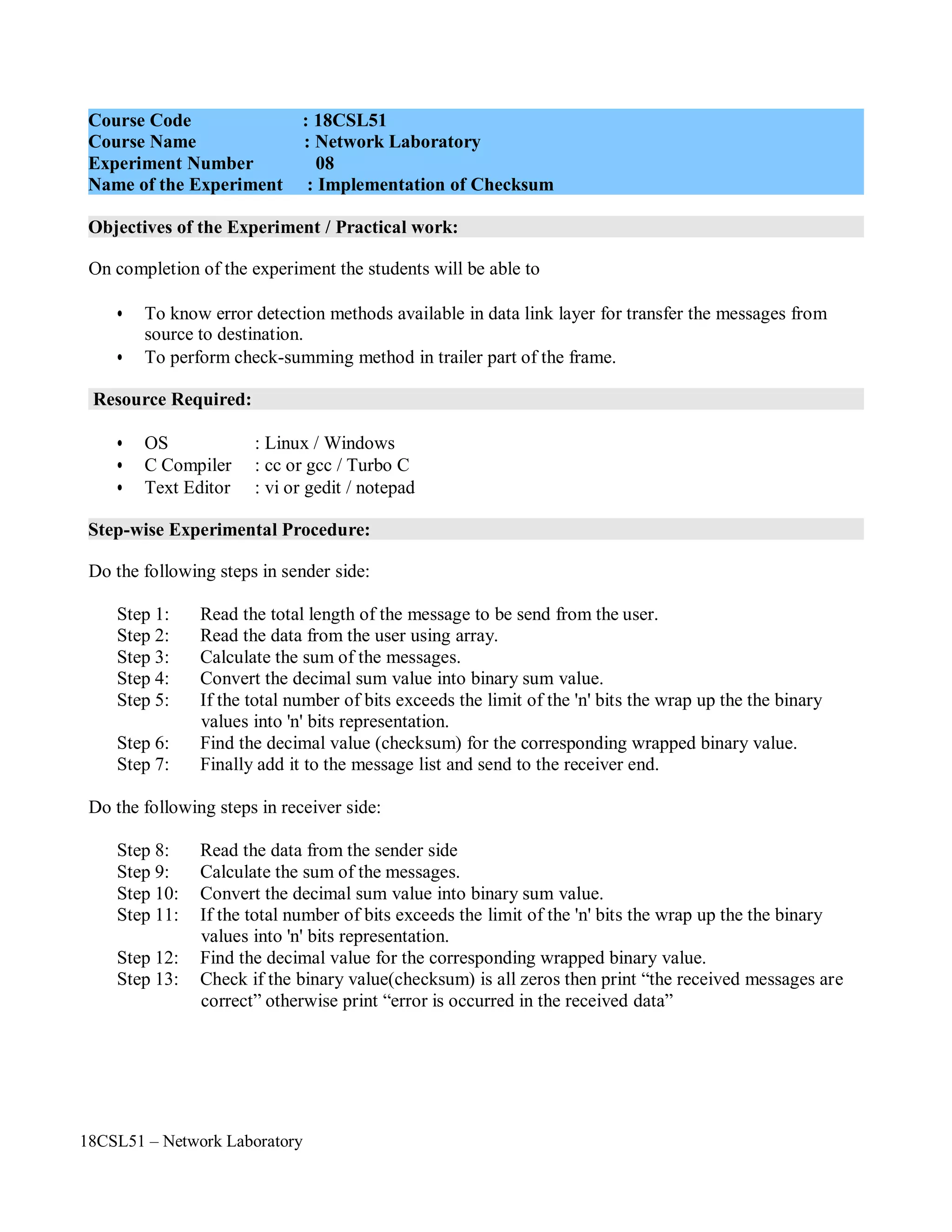
Objectives of the Experiment / Practical work:
Resource Required:
Step-wise Experimental Procedure:
Computations to be Made:
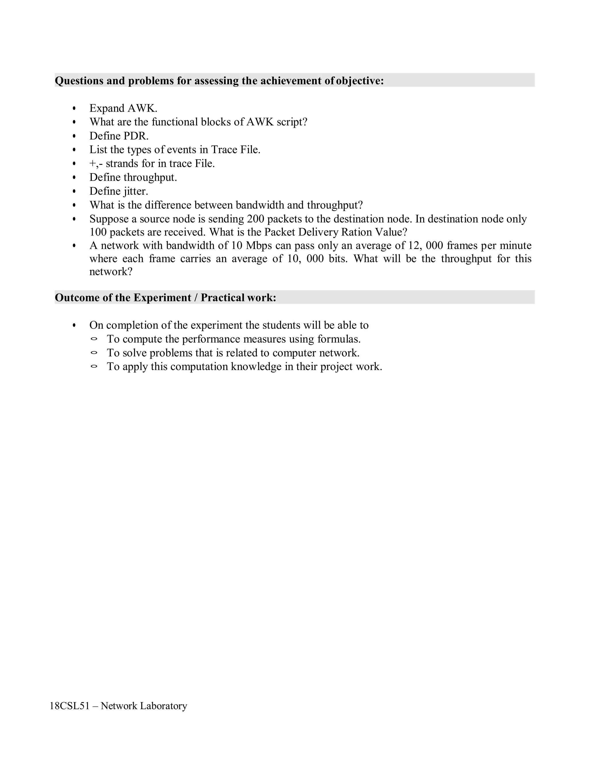
On completion of the experiment the students will be able to
• To understand the various performance measurement parameters PDR, Throughput and Jitter.
• To calculate various network performance measurement parameters such as PDR, Throughput
and Jitter.
• OS : Linux
• Simulation Tool : Network Simulator 2 (ns2)
• Text Editor : vi or gedit
• Package : AWK
Step 1: Create any one type of network topology
Step 2: Run the Simulation and Record the Trace file
Step 3: Write AWK Script to measure the network performance such as PDR, Throughput and
Jitter.
Step 4: Run the AWK Script.
Step 5: Display the results to the user.
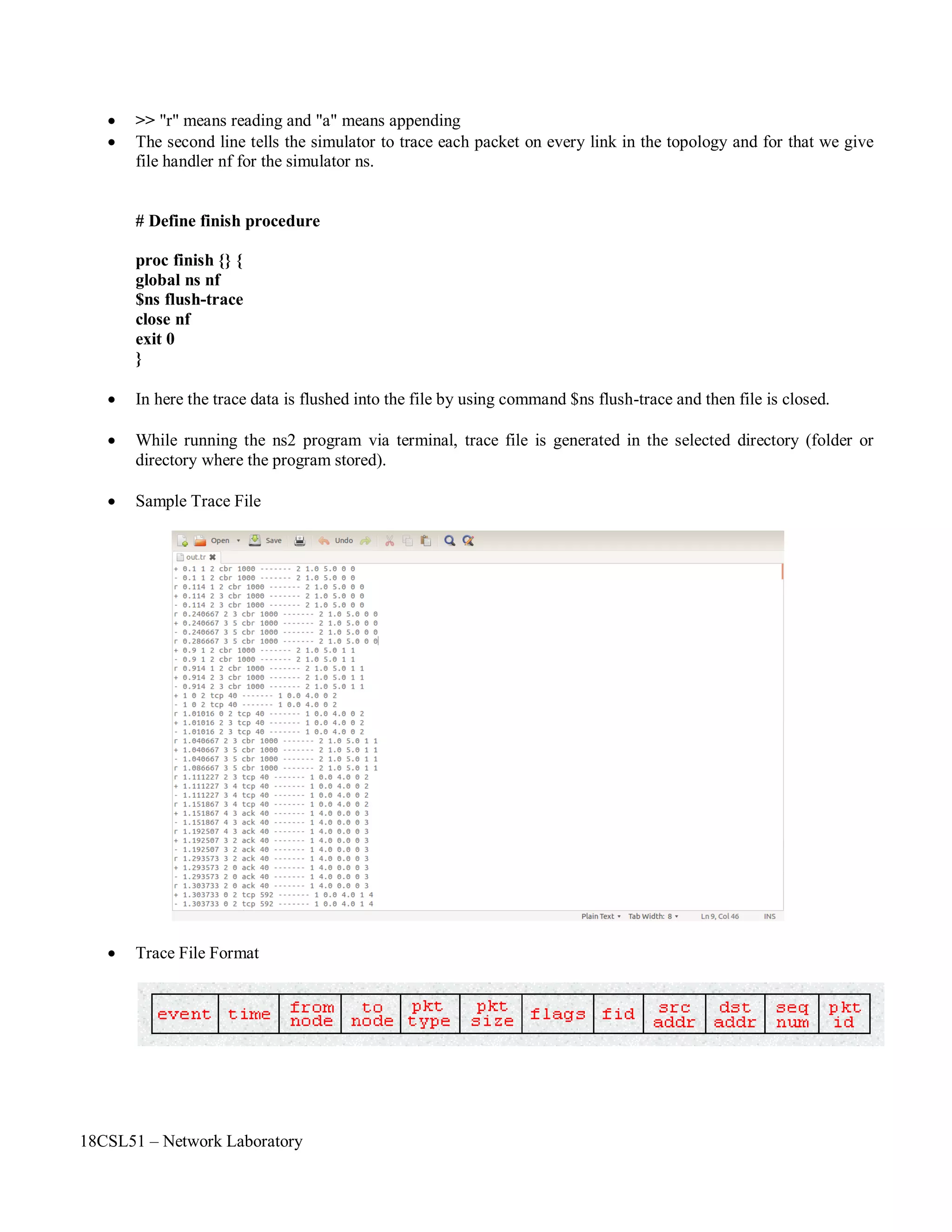
TRACE FILES AND DESCRIPTION
The file written by an application (or by the Coverage Server) to store coverage information or overall
network information and In NS2 , it is called as Trace File.
In order to generate a trace file. we have to create a trace file in Otcl script.
SYNTAX FOR CREATING A TRACE FILE
# Open the trace file
set nf [open out.tr w]
$ns trace-all $nf
which means we are opening a newtrace file named as "out" and also telling that data must be stored in .tr
[trace] format.
"nf" is the file handler that we are used here to handle the trace file.
"w" means write i.e the file out.tr is opened for writing.
Course Code : 18CSL51
Course Name : Network Laboratory
Experiment Number : 03
Name of the Experiment : AWK script to Measure the Network Performance](https://image.slidesharecdn.com/18csl51-networklabmanual-220519112438-6d77913b/75/18CSL51-Network-Lab-Manual-pdf-23-2048.jpg)

![18CSL51 – Network Laboratory
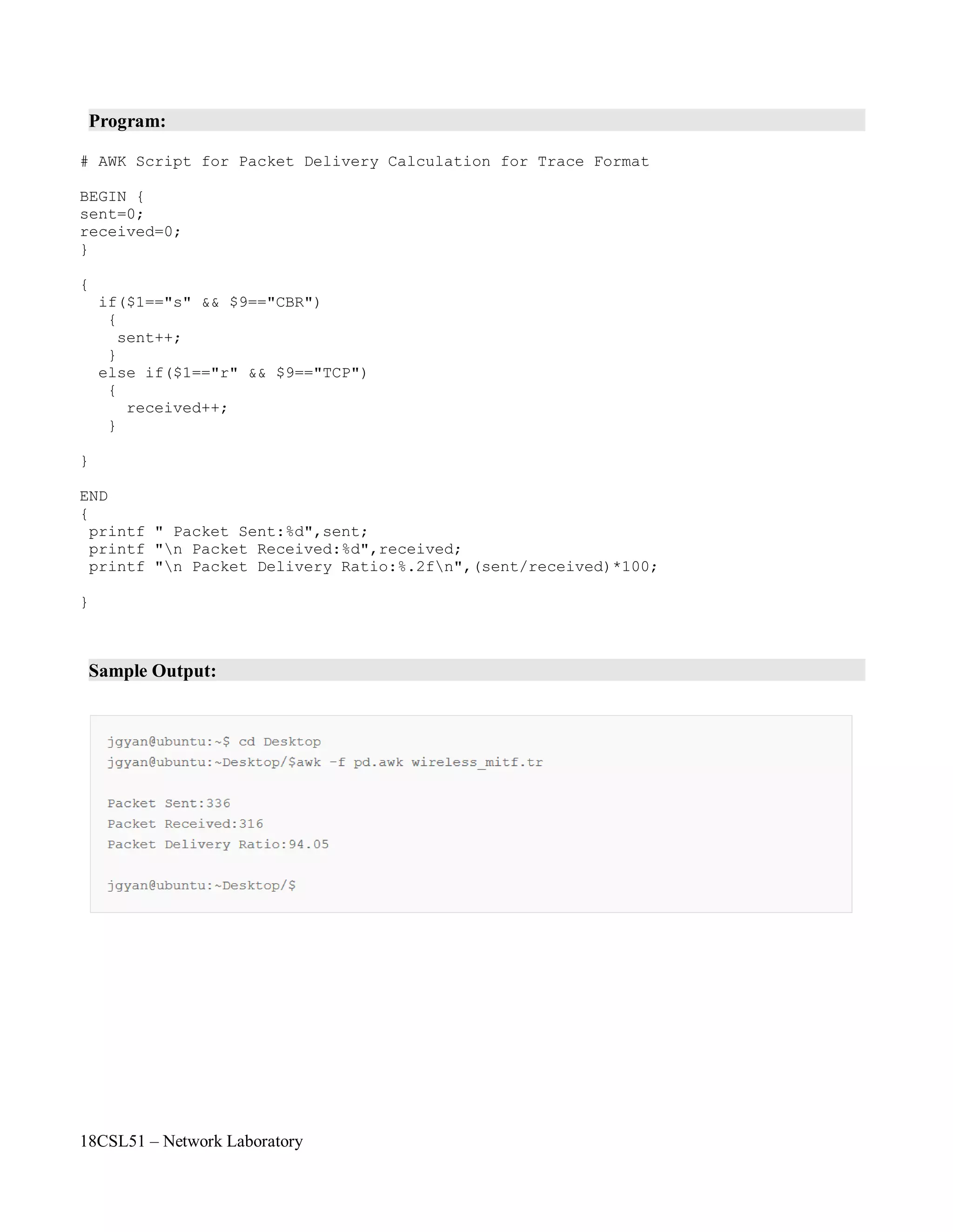
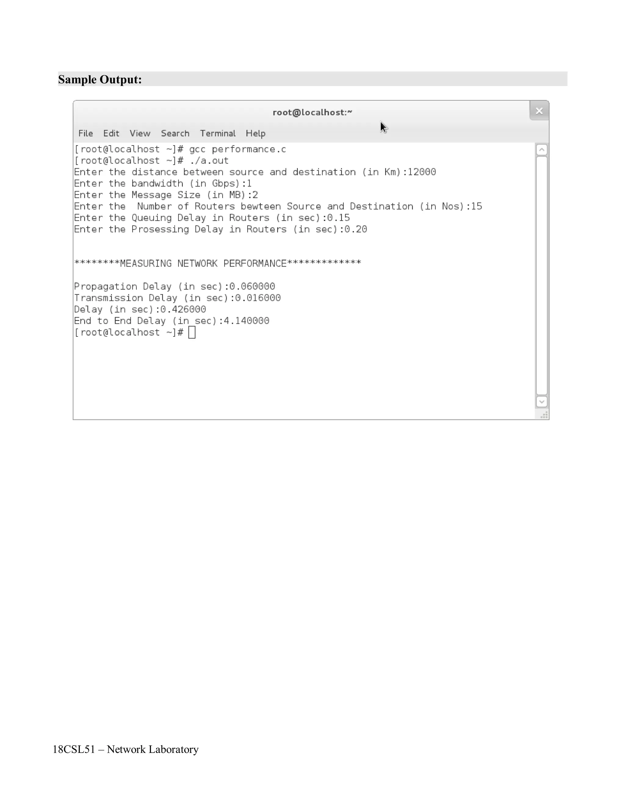
dnodal = dtrans+ dprop+ dproc + dqueu
There is a certain minimum level of delay that will be experienced due to the time it takes to
transmit a packet serially through a link. Onto this is added a more variable level of delay due to
network congestion. IP network delays can range from just a few milliseconds to several hundred
milliseconds.
Propagation delay :
Propagation time measures the time required for a bit to travel from the source to the
destination. The propagation delay is calculated by dividing the distance by the propagation speed.
Propagation delay = Distance / Propagation speed
Transmission delay:
In data communications we don't send just 1 bit, we send a message. The first bit may take a
delay equal to the propagation delay to reach its destination; the last bit also may take the same amount
of time. However, there is a delay between the first bit leaving the sender and the last bit arriving at the
receiver. The first bit leaves earlier and arrives earlier; the last bit leaves later and arrives later. The
time required for transmission of a message depends on the size of the message and the bandwidth of
the channel.
Transmission delay = Message size / Bandwidth
End-to-End Delay:
End-to-End delay refers to the time taken for a packet to be transmitted across a network from
source to destination.
where
dend-end= N[ dtrans+ dprop+ dproc]
dend-end= end-to-end delay
dtrans= transmission delay
dprop= propagation delay
dproc= processing delay
N= number of links (Number of routers + 1)
Note: we have neglected queuing delays.
Each router will have its own dtrans, dprop, dproc hence this formula gives a rough estimate.](https://image.slidesharecdn.com/18csl51-networklabmanual-220519112438-6d77913b/75/18CSL51-Network-Lab-Manual-pdf-30-2048.jpg)

![18CSL51 – Network Laboratory
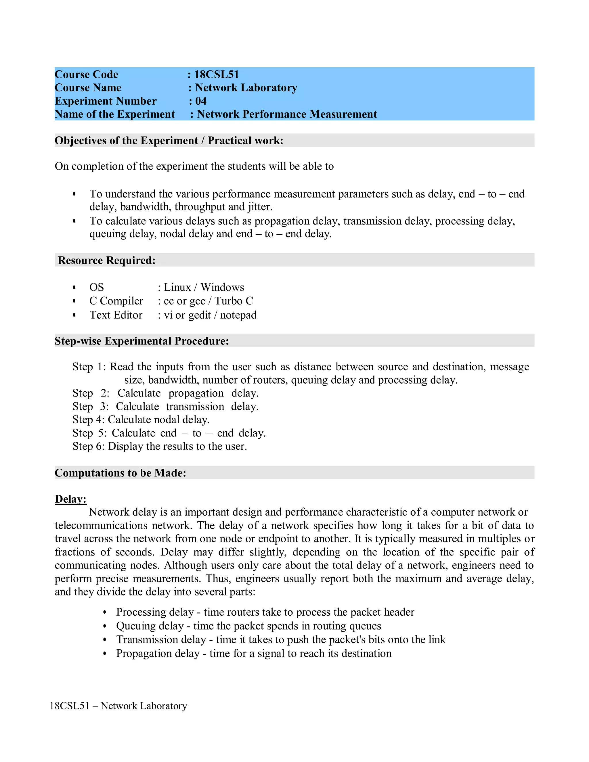
Program:
#include<stdio.h>
#include<stdlib.h>
#define BLACK "033[22;30m"
#define RED "033[01;31m"
#define G "033[01;32m"
main()
{
char str[100],dest[100],str1[100];
int l,i,j,k,c,m,bit[100];
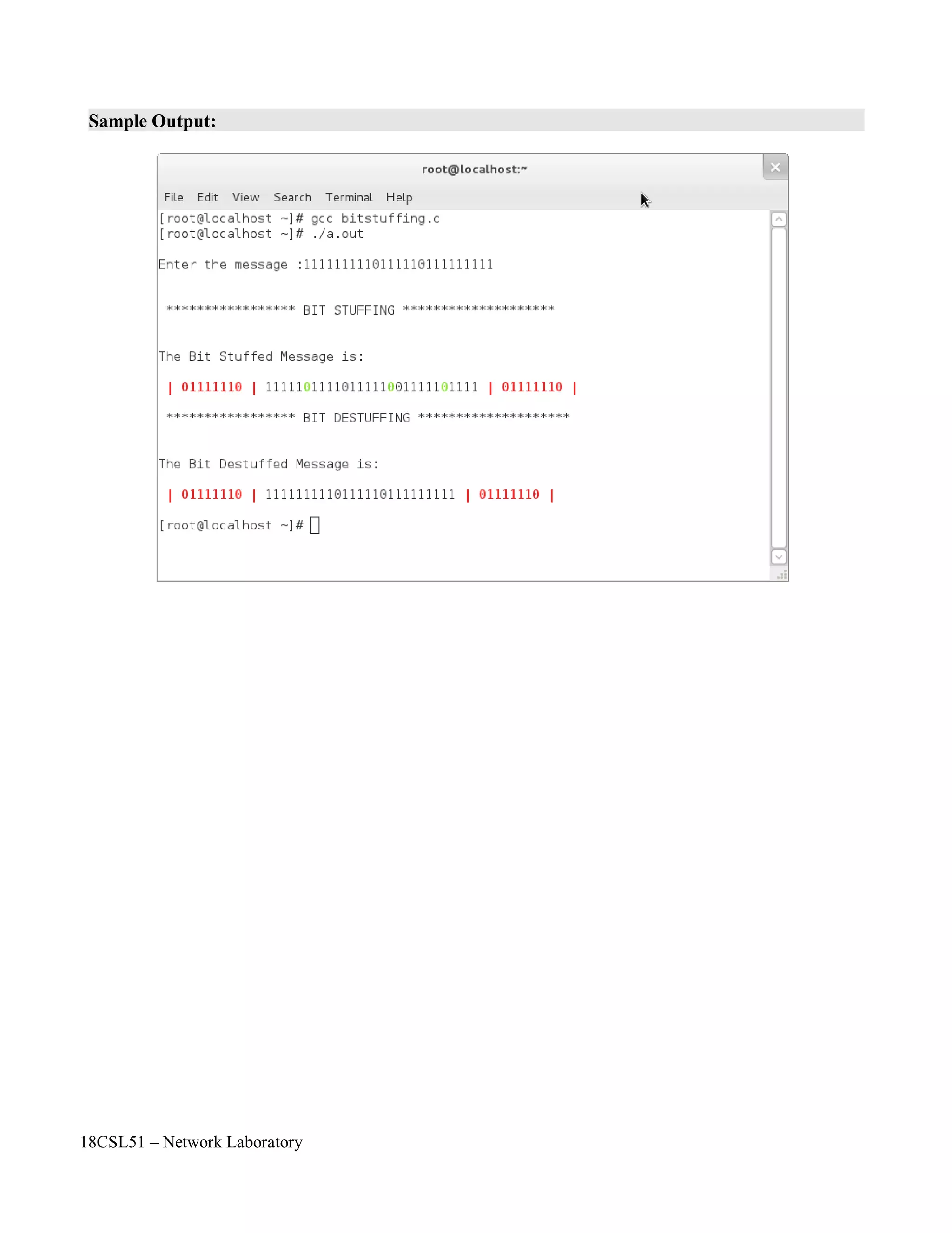
printf("nEnter the message :");
scanf("%s",str);
printf("nn ***************** BIT STUFFING ********************nn");
for(j=0,k=0,c=0,i=0;str[i]!='0';i++)
{
if(str[i]=='1')
{
c++;
if(c==5)
{
}
else
dest[j++]=str[i];
dest[j++]='0';
c=0;
}
else
{
}
}
dest[j++]=str[i];
c=0;
dest[j++]=str[i];
dest[j]='0';
printf("nThe Bit Stuffed Message is:nn");
printf(RED " | 01111110 | " );
for(i=0,c=0;dest[i]!='0';i++)
{
if(dest[i]=='1')
{
c++;](https://image.slidesharecdn.com/18csl51-networklabmanual-220519112438-6d77913b/75/18CSL51-Network-Lab-Manual-pdf-36-2048.jpg)
![18CSL51 – Network Laboratory
printf(BLACK "%c",dest[i]);
if(c==5)
{
}
else
{
}
c=0;
printf(G "%c",dest[++i]);
c=0;
printf(BLACK "%c",dest[i]);
}
}
printf(RED " | 01111110 | "BLACK );
printf("nn ***************** BIT DESTUFFING ********************nn");
for(i=0,k=0,c=0;dest[i]!='0';i++)
{
if(dest[i]=='1')
{
c++;
if(c==5)
{
str1[k++]=dest[i++];
str1[k++]=dest[++i];
if(dest[i]=='1')
c=1;
}
else
else
c=0;
}
else
{
}
}
str1[k++]=dest[i];
str1[k++]=dest[i];
c=0;
str1[k]='0';
printf("nThe Bit Destuffed Message is:nn");
printf(RED " | 01111110 | " BLACK "%s" RED " | 01111110 |nn" BLACK, str1);
}](https://image.slidesharecdn.com/18csl51-networklabmanual-220519112438-6d77913b/75/18CSL51-Network-Lab-Manual-pdf-37-2048.jpg)

![18CSL51 – Network Laboratory
Program:
#include<stdio.h>
#include<stdlib.h>
#define BLACK "033[22;30m"
#define RED "033[01;31m"
#define GREEN "033[01;32m"
main()
{
char str[100],dest[100],str1[100],f;
int l,i,j,k;
printf("nEnetr the name of the flag bit:");
scanf("%c",&f);
printf("nEnter the length of the message:");
scanf("%d",&l);
printf("nEnter the message :");
for(i=0;i<=l;i++)
{
str[i]=getchar();
}
str[i]='0';
printf("nn********************* BYTE STUFFING ************************nn");
printf("nMessage after Byte Stuffing is:nn" GREEN "| %c | " BLACK,f);
for(i=0,j=0;i<=l;i++)
{
if(str[i]=='E')
dest[j++]='E';
if(str[i]==f)
dest[j++]='E';
dest[j++]=str[i];
}
dest[j]='0';
for(i=0;dest[i]!='0';i++)
{
if(dest[i]=='E')
{
}
else
printf(RED "%c" BLACK,dest[i]);
if(dest[i+1]=='E')
printf("%c",dest[++i]);
printf("%c",dest[i]);
}
printf(GREEN " | %c | " BLACK,f);](https://image.slidesharecdn.com/18csl51-networklabmanual-220519112438-6d77913b/75/18CSL51-Network-Lab-Manual-pdf-42-2048.jpg)
![18CSL51 – Network Laboratory
printf("nn********************* BYTE DESTUFFING ***********************nn");
printf("nMessage after Byte Destuffing is:nn" GREEN "| %c | " BLACK,f);
for(i=0,k=0;i<j;i++)
{
if(dest[i]=='E')
{
if(dest[i+1]=='E')
str1[k++]=dest[++i];
}
else
else
str1[k++]=dest[++i];
str1[k++]=dest[i];
}
str1[k]='0';
printf("%s",str1);
printf(GREEN " | %c |nn" BLACK,f);
}](https://image.slidesharecdn.com/18csl51-networklabmanual-220519112438-6d77913b/75/18CSL51-Network-Lab-Manual-pdf-43-2048.jpg)
![18CSL51 – Network Laboratory
Program:
#include<stdio.h>
#include<string.h>
main()
{
char mes[100],parval,sent[100],recieve[100];
int par,i,count=0;
printf("nEnter the message:");
scanf("%s",mes);
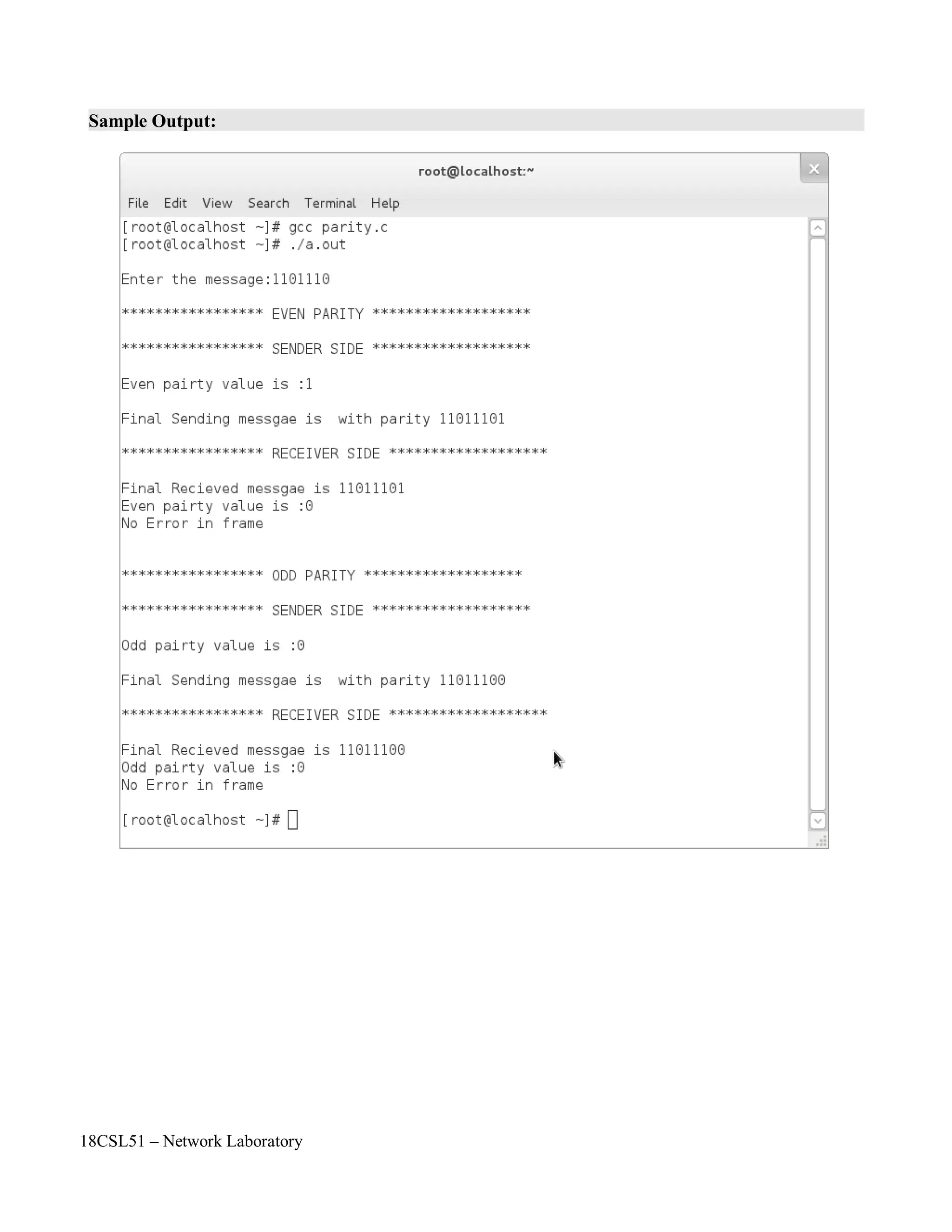
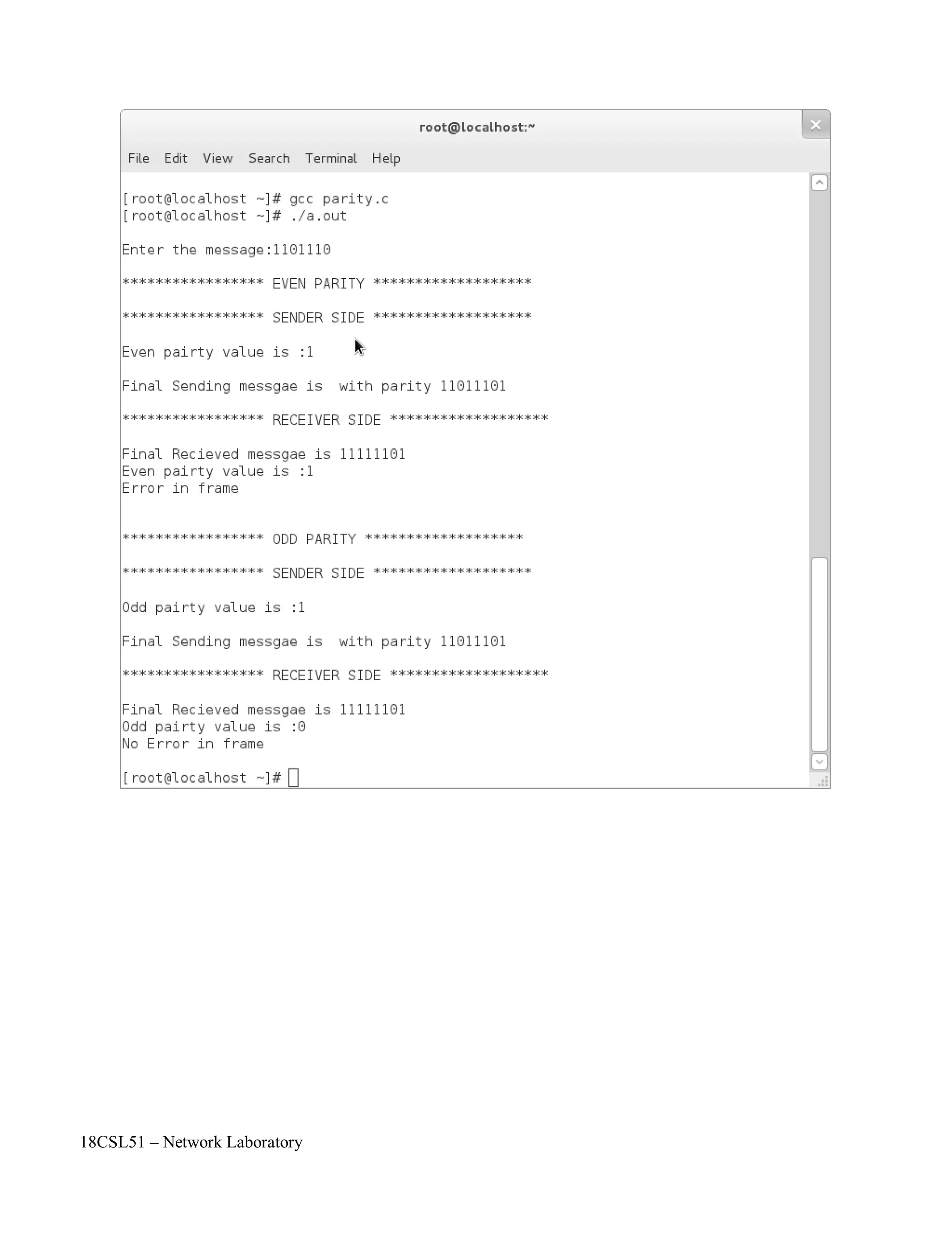
printf("n***************** EVEN PARITY *******************n");
for(i=0;mes[i]!='0';i++)
{
if(mes[i]=='1')
count++;
sent[i]=mes[i];
}
if(count%2==0)
parval='0';
else
parval='1';
sent[i]=parval;
sent[++i]='0';
printf("n***************** SENDER SIDE *******************n");
printf("nEven pairty value is :%cn",parval);
printf("nFinal Sending messgae is with parity %sn",sent);
strcpy(recieve,sent);
//recieve[3]='1'; // -> This is for checking errored frame
printf("n***************** RECEIVER SIDE *******************n");
printf("nFinal Recieved messgae is %s",recieve);
for(i=0,count=0;recieve[i]!='0';i++)
{
if(recieve[i]=='1')
count++;
}
if(count%2==0)
{
}
else
{
}
parval='0';
printf("nEven pairty value is :%cnNo Error in framenn",parval);
parval='1';
printf("nEven pairty value is :%cnError in framenn",parval);](https://image.slidesharecdn.com/18csl51-networklabmanual-220519112438-6d77913b/75/18CSL51-Network-Lab-Manual-pdf-50-2048.jpg)
![18CSL51 – Network Laboratory
printf("n***************** ODD PARITY *******************n");
for(i=0;mes[i]!='0';i++)
{
if(mes[i]=='1')
count++;
sent[i]=mes[i];
}
if(count%2==0)
parval='1';
else
parval='0';
sent[i]=parval;
sent[++i]='0';
printf("n***************** SENDER SIDE *******************n");
printf("nOdd pairty value is :%cn",parval);
printf("nFinal Sending messgae is with parity %sn",sent);
strcpy(recieve,sent);
//recieve[3]='1'; //-> This is for checking errored frame
printf("n***************** RECEIVER SIDE *******************n");
printf("nFinal Recieved messgae is %s",recieve);
for(i=0,count=0;recieve[i]!='0';i++)
{
if(recieve[i]=='1')
count++;
}
if(count%2==0)
{
}
else
{
}
}
parval='1';
printf("nOdd pairty value is :%cnError in framenn",parval);
parval='0';
printf("nOdd pairty value is :%cnNo Error in framenn",parval);](https://image.slidesharecdn.com/18csl51-networklabmanual-220519112438-6d77913b/75/18CSL51-Network-Lab-Manual-pdf-51-2048.jpg)
![18CSL51 – Network Laboratory
Program:
#include<stdio.h>
#include<math.h>
#include<string.h>
int main()
{
int a[10],n,sum=0,i,binary[100]={0};
int j,binary1[100],l,result[10],c=0,k;
int sum1;
printf("n************** SENDER SIDE ******************n");
printf("nEnter the total length of message:");
scanf("%d",&n);
printf("nEnter the data one by one :");
for(i=0;i<n;i++)
{
scanf("%d",&a[i]);
sum+=a[i];
}
printf("nThe messages are:");
for(i=0;i<n;i++)
printf("n%d",a[i]);
printf("nThe sum is: %d",sum);
for(i=0;sum>0;i++)
{
binary1[i]=sum%2;
sum=sum/2;
}
for(;i<8;i++)
binary1[i]=0;
l=i;
for(i=l-1,j=0;i>=0;i--,j++)
binary[j]=binary1[i];
printf("nThe equivalent binary digit is :");
for(i=0;i<l;i++)
printf("%d",binary[i]);
for(c=0,i=l-1;i>=4;i--) {
if(c==0) {
if(binary[i]==1&&binary[i-4]==1) {
result[i-4]=0;
c=1;
}
else if(binary[i]==1&&binary[i-4]==0) {
result[i-4]=1;
c=0;
}
else if(binary[i]==0&&binary[i-4]==0) {](https://image.slidesharecdn.com/18csl51-networklabmanual-220519112438-6d77913b/75/18CSL51-Network-Lab-Manual-pdf-58-2048.jpg)
![18CSL51 – Network Laboratory
}
else {
}
else {
}
result[i-4]=0;
c=0;
result[i-4]=1;
c=0;
if(binary[i]==1&&binary[i-4]==1) {
result[i-4]=1;
c=1;
}
else if(binary[i]==1&&binary[i-4]==0) {
result[i-4]=0;
c=1;
}
else if(binary[i]==0&&binary[i-4]==0) {
result[i-4]=1;
c=0;
}
else {
}
}
}
result[i-4]=0;
c=1;
printf("nThe binary value of wrapped sum is:");
for(i=0;i<4;i++)
printf("%d",result[i]);
printf("nThe binary value of checksum is:");
for(i=0,sum=0,j=3;i<4;i++,j--)
{
sum1=1;
if(result[i]==1)
result[i]=0;
else
result[i]=1;
for(k=1;k<=j;k++,sum1=sum1*2);
sum=sum+(result[i]*sum1);
printf("%d",result[i]);
}
printf("nThe checksum value is : %d",sum);
printf("nThe sender side sending messages are:");
a[n++]=sum;
for(i=0;i<n;i++)
printf("n%d",a[i]);](https://image.slidesharecdn.com/18csl51-networklabmanual-220519112438-6d77913b/75/18CSL51-Network-Lab-Manual-pdf-59-2048.jpg)
![18CSL51 – Network Laboratory
printf("nn*************** RECEIVER SIDE ****************nn");
printf("nThe Reciever side messages recieved messages are:");
sum=0;
//a[0]=3; //to check incorrect message
for(i=0;i<n;i++)
{
printf("n%d",a[i]);
sum=sum+a[i];
}
printf("nThe sum is: %d",sum);
for(i=0;sum>0;i++)
{
binary1[i]=sum%2;
sum=sum/2;
}
for(;i<8;i++)
binary1[i]=0;
l=i;
for(i=l-1,j=0;i>=0;i--,j++)
binary[j]=binary1[i];
printf("nThe equivalent binary digit is :");
for(i=0;i<l;i++)
printf("%d",binary[i]);
for(c=0,i=l-1;i>=4;i--) {
if(c==0) {
if(binary[i]==1&&binary[i-4]==1) {
result[i-4]=0;
c=1;
}
else if(binary[i]==1&&binary[i-4]==0) {
result[i-4]=1;
c=0;
}
else if(binary[i]==0&&binary[i-4]==0) {
result[i-4]=0;
c=0;
}
else {
result[i-4]=1;
c=0;
}
else {
}
if(binary[i]==1&&binary[i-4]==1) {
result[i-4]=1;
c=1;
}](https://image.slidesharecdn.com/18csl51-networklabmanual-220519112438-6d77913b/75/18CSL51-Network-Lab-Manual-pdf-60-2048.jpg)
![18CSL51 – Network Laboratory
else if(binary[i]==1&&binary[i-4]==0) {
result[i-4]=0;
c=1;
}
else if(binary[i]==0&&binary[i-4]==0) {
result[i-4]=1;
c=0;
}
else {
}
}
}
result[i-4]=0;
c=1;
printf("nThe binary value of wrapped sum is:");
for(i=0;i<4;i++)
printf("%d",result[i]);
printf("nThe binary value of checksum is:");
for(i=0,sum=0,j=3;i<4;i++,j--)
{
sum1=1;
if(result[i]==1)
result[i]=0;
else
result[i]=1;
for(k=1;k<=j;k++,sum1=sum1*2);
sum=sum+(result[i]*sum1);
printf("%d",result[i]);
}
printf("nThe checksum value is : %d",sum);
if(sum==0)
printf("nThe recieved message is correctn");
else
printf("nThe recieved message is incorrectn");
}](https://image.slidesharecdn.com/18csl51-networklabmanual-220519112438-6d77913b/75/18CSL51-Network-Lab-Manual-pdf-61-2048.jpg)
![18CSL51 – Network Laboratory
Objectives of the Experiment / Practical work:
Resource Required:
Step-wise Experimental Procedure:
On completion of the experiment the students will be able to
• To know detect the errors at the receiver side.
• To implement CRC method for error detection in data link layer.
• OS : Linux / Windows
• C Compiler : cc or gcc / Turbo C
• Text Editor : vi or gedit / notepad
Do the following steps in sender side:
Step 1: Read the dataword (message) to be send from the user using an array.
Step 2: Read the 'n' bit common divisor from the user using an array.
Step 3: At sender side append n-1 zeros in dataword
Step 4: check if the MSB bit position of the divisor and dataword is same then do the Ex-OR
operation as stated below
crc[j]=itoc((ctoi(crc[j]))^(ctoi(div[j])));
Step 5: Repeat step 4 until the LSB bit of the dataword comes to end. Finally the n-1 bit
remainder value (CRC value) is replaced with appended zeros
position of the dataword. This message is called codeword.
Step 6: At last, the codeword (dataword+remainder) is send to the receiver.
Do the following steps in receiver side:
Step 7: Read the codeword rom the sender side
Step 8: check if the MSB bit position of the divisor and dataword is same then do the Ex-OR
operation as stated below
crc[j]=itoc((ctoi(crc[j]))^(ctoi(div[j])));
Step 9: Repeat step 4 until the LSB bit of the dataword comes to end.
Step 10: Display the receiver side remainder value.
Step 11: Check if the remainder value is all zeros then print “the received messages are
correct” otherwise print “error is occurred in the received data”
Course Code : 18CSL51
Course Name : Network Laboratory
Experiment Number 09
Name of the Experiment : Implementation of CRC](https://image.slidesharecdn.com/18csl51-networklabmanual-220519112438-6d77913b/75/18CSL51-Network-Lab-Manual-pdf-64-2048.jpg)
![18CSL51 – Network Laboratory
Program:
#include<stdio.h>
#include<string.h>
int ctoi(char a) {
return (a-48);
}
char itoc(int a) {
return (a+48);
}
void main()
{
char ip[100],ipm[100],div[20],crc[10],sent[100],rec[100];
int i,lm,ld,j;
printf("n************ SENDER SIDE(CRC ENCODING)***********n");
printf("nEnter Data Word ( Message):");
scanf("%s",ip);
printf("nEnter Divisor :");
scanf("%s",div);
strcpy(ipm,ip);
lm=strlen(ipm);
ld=strlen(div);
if(lm>=ld)
{
for(i=lm,j=0;j<ld-1;j++)
ipm[i++]='0';
ipm[i]='0';
printf("nThe Data Word After Appending Zeros: %s",ipm);
for(i=0;i<ld;i++)
crc[i]=ipm[i];
crc[i]='0';
for(;i<strlen(ipm);i++)
{
if(crc[0]=='1')
{
for(j=0;j<ld;j++)
{
crc[j]=itoc((ctoi(crc[j]))^(ctoi(div[j])));
}
}
crc[ld]=ipm[i];
crc[ld+1]='0';
for(j=0;crc[j]!='0';j++)
crc[j]=crc[j+1];
crc[j]='0';
}](https://image.slidesharecdn.com/18csl51-networklabmanual-220519112438-6d77913b/75/18CSL51-Network-Lab-Manual-pdf-68-2048.jpg)
![18CSL51 – Network Laboratory
for(j=0;crc[j]!='0';j++)
crc[j]=crc[j+1];
crc[j]='0';
printf("nThe CRC Remainder is : %s",crc);
strcat(sent,ip);
strcat(sent,crc);
printf("nThe Code Word in sender side is: %s",sent);
printf("nn************ RECEIVER SIDE(CRC DECODING)*************");
strcpy(rec,sent);
//rec[2]='1'; // to check error data
printf("nnThe recieved message in reciever side is: %s",rec);
for(i=0;i<ld;i++)
crc[i]=rec[i];
crc[i]='0';
for(;i<strlen(rec);i++)
{
if(crc[0]=='1')
{
for(j=0;j<ld;j++)
{
crc[j]=itoc((ctoi(crc[j]))^(ctoi(div[j])));
}
}
crc[ld]=rec[i];
crc[ld+1]='0';
for(j=0;crc[j]!='0';j++)
crc[j]=crc[j+1];
crc[j]='0';
}
for(j=0;crc[j+1]!='0';j++)
crc[j]=crc[j+1];
crc[j]='0';
for(j=0;crc[j]!='0';j++)
{
if(crc[j]!='0')
break;
}
}
else
printf("nnThe CRC Remainder is: %s",crc);
if(j==strlen(crc))
printf("nnThe received message is error free!nn");
else
printf("nError in recieved message!!!nn");
printf("nEnter proper divisor");
}](https://image.slidesharecdn.com/18csl51-networklabmanual-220519112438-6d77913b/75/18CSL51-Network-Lab-Manual-pdf-69-2048.jpg)
![18CSL51 – Network Laboratory
Objectives of the Experiment / Practical work:
Resource Required:
Step-wise Experimental Procedure:
On completion of the experiment the students will be able to
• To understand the uses of IP address.
• To know the various classes of IP Address and range of each classes IP Address.
• To identify the classes of IP Address.
• OS : Linux / Windows
• C Compiler : cc or gcc / Turbo C
• Text Editor : vi or gedit / notepad
Step 1: Read the IP Address as input from the user (ex. 10.1.1.1) using character array ip[100].
Step 2: Find out the string length using strlen() function.
Step 3: Check out the IP address format using isdigit() function (ex. 12.3a.1.1, 10/1.1.1.12 are
incorrect IP Address format)
Step 4: Check the loopback IP address (127.0.0.0) by using strcmp() function .
Step 5: Convert the IP address as decimal number from string by using the following line of
coding
for(i=0,s1=0;ip[i]!='.';i++)
s1=(s1*10)+ip[i]-48;
Step 6: Check the IP address range from 0 to 255 for each part (totally 4: namely s1,s2,s3, s4)
Step 7: Check and print the classes of IP address according to the first portion of the IP address
range.
Step 8: If s1 range of IP address is between 0 to 127 then print the IP address is Class A.
Step 9: If s1 range of IP address is between 128 to 191 then print the IP address is Class B.
Step 10: If s1 range of IP address is between 192 to 223 then print the IP address is Class C.
Step 11: If s1 range of IP address is between 224 to 239 then print the IP address is Class D.
Step 12: If s1 range of IP address is between 240 to 255 then print the IP address is Class E.
Course Code : 18CSL51
Course Name : Network Laboratory
Experiment Number 10
Name of the Experiment : Finding the Classes of IP Address](https://image.slidesharecdn.com/18csl51-networklabmanual-220519112438-6d77913b/75/18CSL51-Network-Lab-Manual-pdf-71-2048.jpg)
![18CSL51 – Network Laboratory
Program:
#include<stdio.h>
#include<string.h>
#include<ctype.h>
main()
{
char ip[100],part1[100],part2[100],part3[100],part4[100];
int i,j,s1,s2,s3,s4,c,sp,d,l;
printf("nn ***************** IP ADDRESS CLASSES ********************nn");
printf("nEnter IP Address : ");
scanf("%s",ip);
l=strlen(ip);
// Testt Case 1: To Check IP Address Format
for(i=0,d=0;ip[i]!='0';i++)
{
if(isdigit(ip[i]))
d++;
else if((ip[i]=='.')&&(d>0))
d=0;
else
break;
}
if(d==0||(i<l))
{
printf("n The IP Address is in Wrong Format !!! n ");
printf("So please enter correct IP Address:n");
main();
}
// Test Case 2: To Check Loopback IP Address
else if(strcmp(ip,"127.0.0.0")==0)
printf("n%s is a Loopback addressnn");](https://image.slidesharecdn.com/18csl51-networklabmanual-220519112438-6d77913b/75/18CSL51-Network-Lab-Manual-pdf-74-2048.jpg)
![18CSL51 – Network Laboratory
else
{
// To Convert the the IP Address as Decimal Number from String
for(i=0,s1=0;ip[i]!='.';i++)
s1=(s1*10)+ip[i]-48;
for(i=i+1,s2=0;ip[i]!='.';i++)
s2=(s2*10)+ip[i]-48;
for(i=i+1,s3=0;ip[i]!='.';i++)
s3=(s3*10)+ip[i]-48;
for(i=i+1,s4=0;ip[i]!='0';i++)
s4=(s4*10)+ip[i]-48;
// Test Case 3: To Check IP Addess Range 0 - 255 for each part
if((s1>255)||(s2>255)||(s3>255)||(s4>255))
{
}
else
{
printf("n The IP Address is in Wrong Format !!! n");
printf("So please enter correct IP Address:n");
main();
// To Find the Classess of IP Address
if((s1>=0)&&(s1<128))
printf("n %s is Class A IP Addressnn",ip);
else if((s1>127)&&(s1<192))
printf("n %s is Class B IP Addressnn",ip);
else if((s1>191)&&(s1<224))
printf("n %s is Class C IP Addressnn",ip);
else if((s1>223)&&(s1<240))
printf("n %s is Class D IP Addressnn",ip);
else
printf("n %s is Class E IP Addressnn",ip);
}
}
}](https://image.slidesharecdn.com/18csl51-networklabmanual-220519112438-6d77913b/75/18CSL51-Network-Lab-Manual-pdf-75-2048.jpg)
![18CSL51 – Network Laboratory
Program:
#include<stdio.h>
#include<ctype.h>
#include<string.h>
main()
{
FILE *f1;
int i,d,l;
char mac[100],ip[100],inip[100];
f1=fopen("/root/ARPTABLE.txt","r");
printf("n**************** ADDRESS RESOLUTION PROTOCOL*************nn");
if(f1==NULL)
printf("nCann't open the file");
else
{
printf("nEnter the ip address of the host:");
scanf("%s",inip);
l=strlen(inip);
for(i=0,d=0;inip[i]!='0';i++) {
if(isdigit(inip[i]))
d++;
else if((inip[i]=='.')&&(d>0))
d=0;
else
break;
}
if(d==0||(i<l)) {
printf("n The IP Address is in Wrong Format !!! n");
printf("n So please enter correct IP Address.n");
main();
}
else {
while((fscanf(f1,"%s%s",ip,mac))==2) {
if(strcmp(inip,ip)==0)
{
printf("nThe Equivalent MAC address is %snn",mac);
break;
}
}
Databasen");
}
}
}
if(feof(f1))
printf("nEquivalent MAC address is not present in Database. So update your](https://image.slidesharecdn.com/18csl51-networklabmanual-220519112438-6d77913b/75/18CSL51-Network-Lab-Manual-pdf-80-2048.jpg)
![18CSL51 – Network Laboratory
Program:
#include<stdio.h>
#include<ctype.h>
#include<string.h>
main()
{
FILE *f1;
int i,sp;
char mac[100],ip[100],inmac[100];
f1=fopen("/root/ARPTABLE.txt","r");
printf("n*********** REVERSE ADDRESS RESOLUTION PROTOCOL**********nn");
if(f1==NULL)
printf("nCann't open the file");
else
{
printf("nEnter the MAC Address of the Host:");
scanf("%s",inmac);
for(i=0,sp=0;inmac[i]!='0';i++)
{
if(!isalnum(inmac[i]))
sp++;
if(islower(inmac[i])||((inmac[i]-65)>5))
break;
}
if(inmac[i]!='0'|| (sp!=5))
{
}
else
{
printf("nThe MAC address is not in exact formatn");
printf("nSo please enter correct MAC Address.n");
main();
while((fscanf(f1,"%s%s",ip,mac))==2)
{
if(strcmp(inmac,mac)==0)
{
printf("nThe Equivalent IP Address is: %snn",ip);
break;
}
}
if(feof(f1))
printf("nEquivalent IP address is not present in Database. So update your Databasen");
}
}
}](https://image.slidesharecdn.com/18csl51-networklabmanual-220519112438-6d77913b/75/18CSL51-Network-Lab-Manual-pdf-86-2048.jpg)
![18CSL51 – Network Laboratory
Program:
#include<stdio.h>
#define inf 999
#define size 100
main()
{
int a[size][size],i,j,n,v1,v2,lcost;
int dij(int[][j],int,int,int);
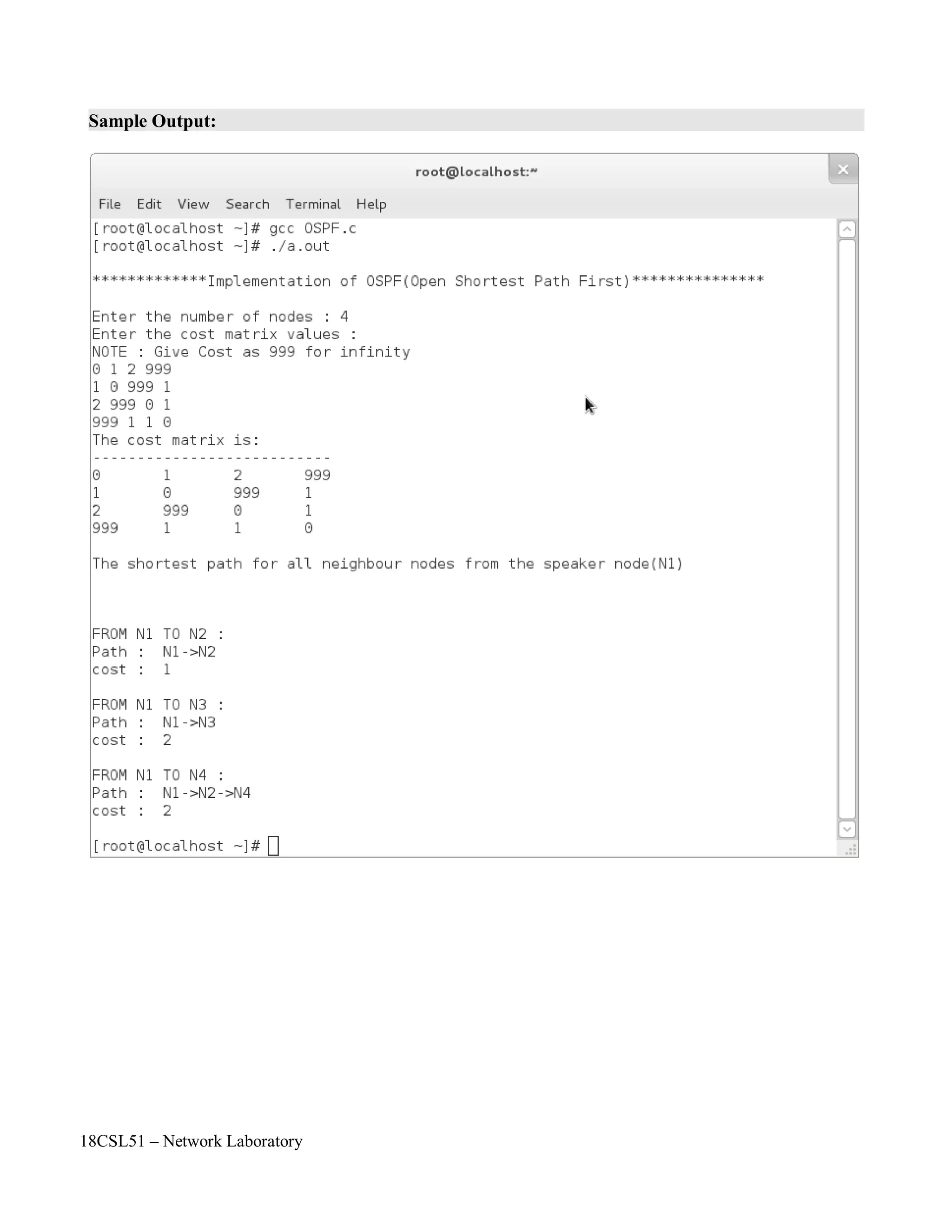
printf("n*********Implementation of OSPF(Open Shortest Path First)***********nn");
printf("Enter the number of nodes : ");
scanf("%d",&n);
//To get Cost Matrix of Autonomous System
printf("Enter the cost matrix values :nNOTE : Give Cost as 999 for infinityn");
for(i=0;i<n;i++)
{
for(j=0;j<n;j++)
{
scanf("%d",&a[i][j]);
}
}
//To print the cost matrix
printf("The cost matrix is:n --------------------------n");
for(i=0;i<n;i++)
{
for(j=0;j<n;j++)
printf("%dt",a[i][j]);
printf("n");
}
//To display Shortest Path
printf("nThe shortest path for all neighbour nodes from the speaker node(N1)nn");
for(j=0;j<n;j++)
{
if(j!=0)
{
v2=j;
printf("nnFROM N%d TO N%d : nPath :t",1,(v2+1));
lcost=dij(a,n,0,v2); //Use Dijkstras algorithm to find shortest path
printf("cost :t%d",lcost);
}
}
printf("nn");
return 0;
}](https://image.slidesharecdn.com/18csl51-networklabmanual-220519112438-6d77913b/75/18CSL51-Network-Lab-Manual-pdf-96-2048.jpg)
![18CSL51 – Network Laboratory
//Dijkstras algorithm
int dij(int a[size][size],int n,int v1,int v2)
{
int length[size],set[size],path[size],i,j,s,z,tmp,temp[size],c=0,f=0;
s=v1;
z=v2;
int srch_min(int[],int[],int);
for(i=0;i<n;i++)
set[i]=0;
for(i=0;i<n;i++) {
if(a[s][i]==0) {
length[i]=inf;
path[i]=0;
}
else {
}
}
length[i]=a[s][i];
path[i]=s;
set[s]=1;
length[s]=0;
while(set[z]!=1)
{
j=srch_min(length,set,n); //To find Minimum cost path
set[j]=1;
for(i=0;i<n;i++) {
if(set[i]!=1) {
if(a[i][j]!=0) {
if(length[j]+a[i][j]<length[i]) {
length[i]=length[j]+a[i][j];
path[i]=j;
}}}}
}
j=0;
i=z;
while(i!=s) {
tmp=path[i];
temp[j]=tmp;
i=tmp;
j++;
c++;
}](https://image.slidesharecdn.com/18csl51-networklabmanual-220519112438-6d77913b/75/18CSL51-Network-Lab-Manual-pdf-97-2048.jpg)
![18CSL51 – Network Laboratory
for(j=c-1;j>=0;j--)
{
printf("N%d->",(temp[j]+1));
if(temp[j]==z)
f=1;
}
if(f!=1)
printf("N%d",(z+1));
printf("n");
return length[z];
}
//To find Minimum cost
int srch_min(int length[],int set[],int n)
{
int min,i,min_index;
min=99999,min_index;
for(i=0;i<n;i++) {
if(set[i]!=1) {
if(length[i]<min) {
min=length[i];
min_index=i;
}}}
return min_index;
}](https://image.slidesharecdn.com/18csl51-networklabmanual-220519112438-6d77913b/75/18CSL51-Network-Lab-Manual-pdf-98-2048.jpg)
![18CSL51 – Network Laboratory
Program:
#include<stdio.h>
#define inf 9999
#define size 100
main()
{
int a[size][size],i,j,n,v1,v2,lcost,k,p=1;
int nr[10];
char rn[26];
int dij(int[][j],int,int,int,int[],char[]);
//To Read Number of AS and Number of Nodes in Each AS
printf("n*********Implementation of BGP(Border Gateway Protocol)***********nn");
printf("Enter the number of Autonomous Systems(AS) : ");
scanf("%d",&n);
for(i=0;i<n;i++) {
printf("nEnter the No of Nodes in AS%d: ",i+1);
scanf("%d",&nr[i]);
}
//To Read the Cost Matrix Values for the AS
printf("nEnter the Cost Matrix Value for the AS:nNOTE: Use 999 for Infinitynn");
for(i=0;i<n;i++) {
for(j=0;j<n;j++) {
scanf("%d",&a[i][j]);
}
}
//To Display the AS Cost Matrix
printf("nThe AS(Autonomous Systems) Cost Matrix :n");
for(i=0;i<n;i++) {
for(j=0;j<n;j++)
printf("%dt",a[i][j]);
printf("n");
}
//To Name Nodes in the AS(like A1,B1,etc.,)
for(i=0;i<n;i++)
rn[i]=65+i;
//To print the initial Table values
printf("n******The Initial Table values in all Nodes in the AS*******nn");
for(i=0;i<n;i++) {
printf("Autonomous System%d (%c%d Table) :n",i+1,rn[i],p);
printf("HosttPathn------------ n");
for(j=0;j<nr[i];j++)
printf("%c%dtAS%dn",rn[i],j+1,i+1);
printf("n");
}](https://image.slidesharecdn.com/18csl51-networklabmanual-220519112438-6d77913b/75/18CSL51-Network-Lab-Manual-pdf-105-2048.jpg)
![18CSL51 – Network Laboratory
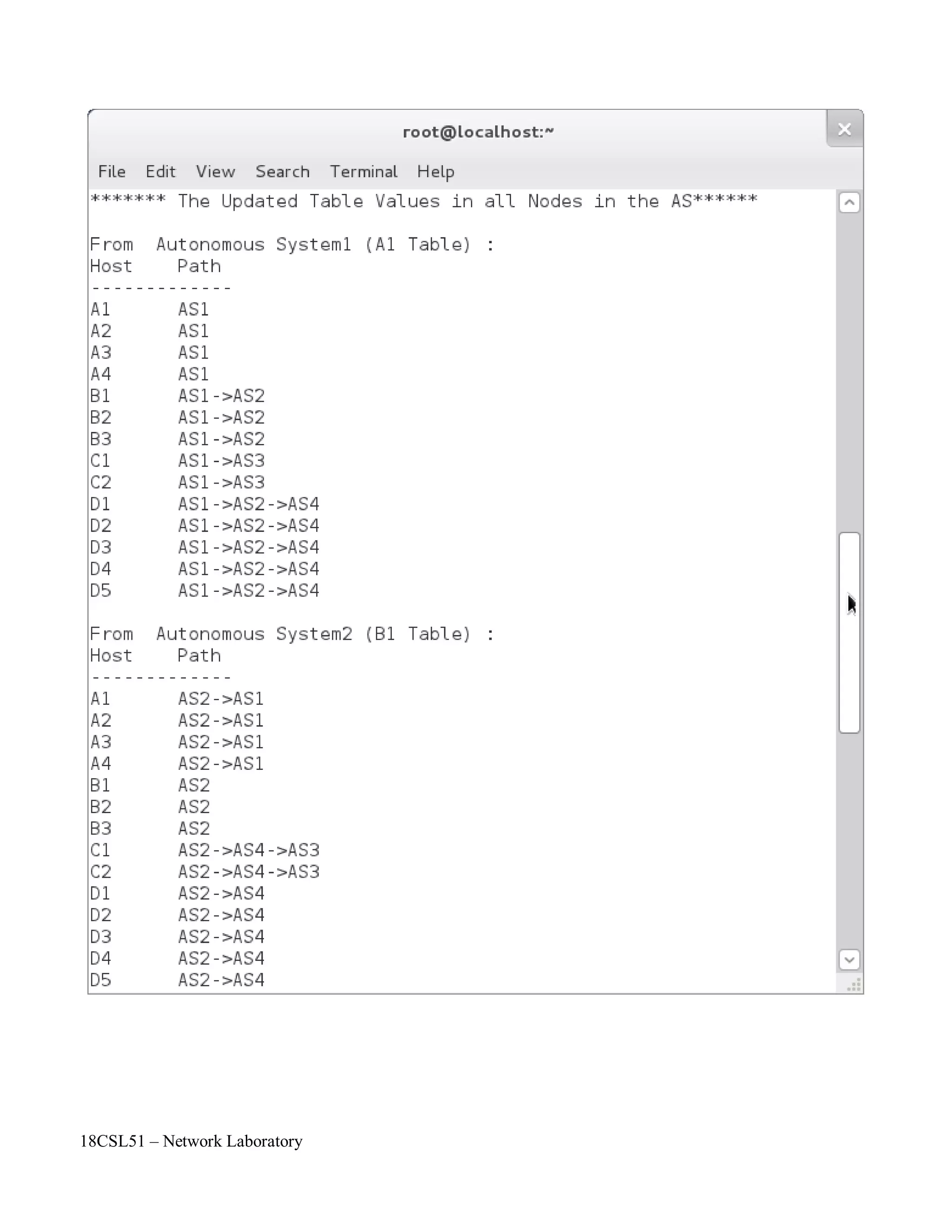
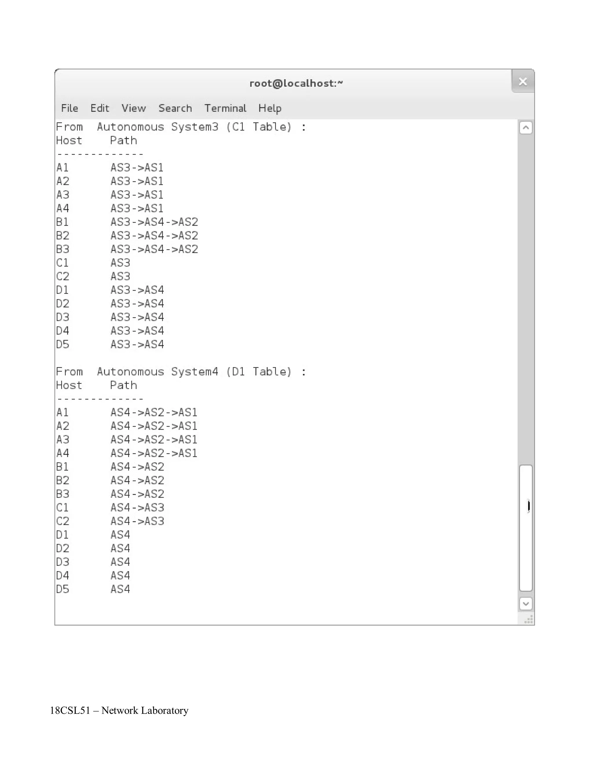
//To print the Updated Table Values
printf("******* The Updated Table Values in all Nodes in the AS******n");
for(k=0;k<n;k++)
{
v1=k;
printf("nFrom Autonomous System%d (%c%d Table):nHosttPathn -n",k+1,rn[k],p);
for(j=0;j<n;j++) {
if(j==v1) {
for(i=0;i<nr[j];i++)
printf("%c%dtAS%dn",rn[j],i+1,j+1);
}
else {
for(i=0;i<nr[j];i++) {
v2=j;
printf("%c%dt",rn[j],i+1);
lcost=dij(a,n,v1,v2,nr,rn);//To Call Dijkstra's Algorithm
}
}
}
}
printf("nn");
return 0;
}
//Dijkstra's Algorithm to find shortest path
int dij(int a[size][size],int n,int v1,int v2,int nr[10],char rn[26])
{
int length[size],set[size],path[size],i,j,s,z,tmp,temp[size],c=0,f=0;
s=v1;
z=v2;
int srch_min(int[],int[],int);
for(i=0;i<n;i++)
set[i]=0;
for(i=0;i<n;i++) {
if(a[s][i]==0) {
length[i]=inf;
path[i]=0;
}
else {
length[i]=a[s][i];
path[i]=s;
}
}](https://image.slidesharecdn.com/18csl51-networklabmanual-220519112438-6d77913b/75/18CSL51-Network-Lab-Manual-pdf-106-2048.jpg)
![18CSL51 – Network Laboratory
set[s]=1;
length[s]=0;
while(set[z]!=1) {
j=srch_min(length,set,n);//To find Minimum Cost Path
set[j]=1;
for(i=0;i<n;i++) {
if(set[i]!=1) {
if(a[i][j]!=0) {
if(length[j]+a[i][j]<length[i]) {
length[i]=length[j]+a[i][j];
path[i]=j;
}}}}
}
j=0;
i=z;
while(i!=s) {
tmp=path[i];
temp[j]=tmp;
i=tmp;
j++;
c++;
}
for(j=c-1;j>=0;j--) {
printf("AS%d->",temp[j]+1);
if(temp[j]==z)
f=1;
}
if(f!=1)
printf("AS%d",z+1);
printf("n");
return length[z];
}
//To find Minimum Cost path
int srch_min(int length[],int set[],int n)
{
int min,i,min_index;
min=99999,min_index;
for(i=0;i<n;i++) {
if(set[i]!=1) {
if(length[i]<min) {
min=length[i];
min_index=i;
} }}
return min_index;
}](https://image.slidesharecdn.com/18csl51-networklabmanual-220519112438-6d77913b/75/18CSL51-Network-Lab-Manual-pdf-107-2048.jpg)
![18CSL51 – Network Laboratory
Objectives of the Experiment / Practical work:
Resource Required:
Step-wise Experimental Procedure:
On completion of the experiment the students will be able to
• To understand the various client side socket operations in TCP/IP model.
• To connect any server by using their corresponding IP Address.
• OS : Linux
• C Compiler : cc or gcc
• Text Editor : vi or gedit
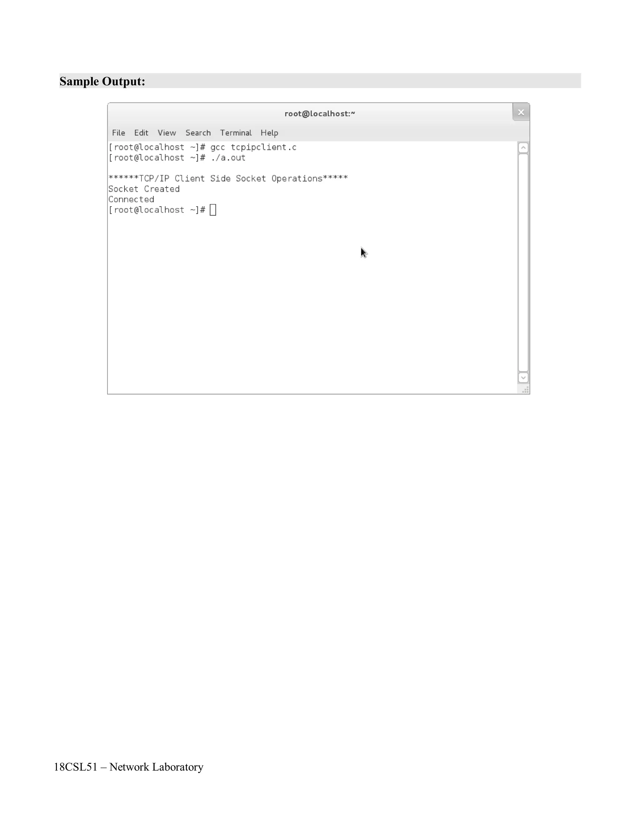
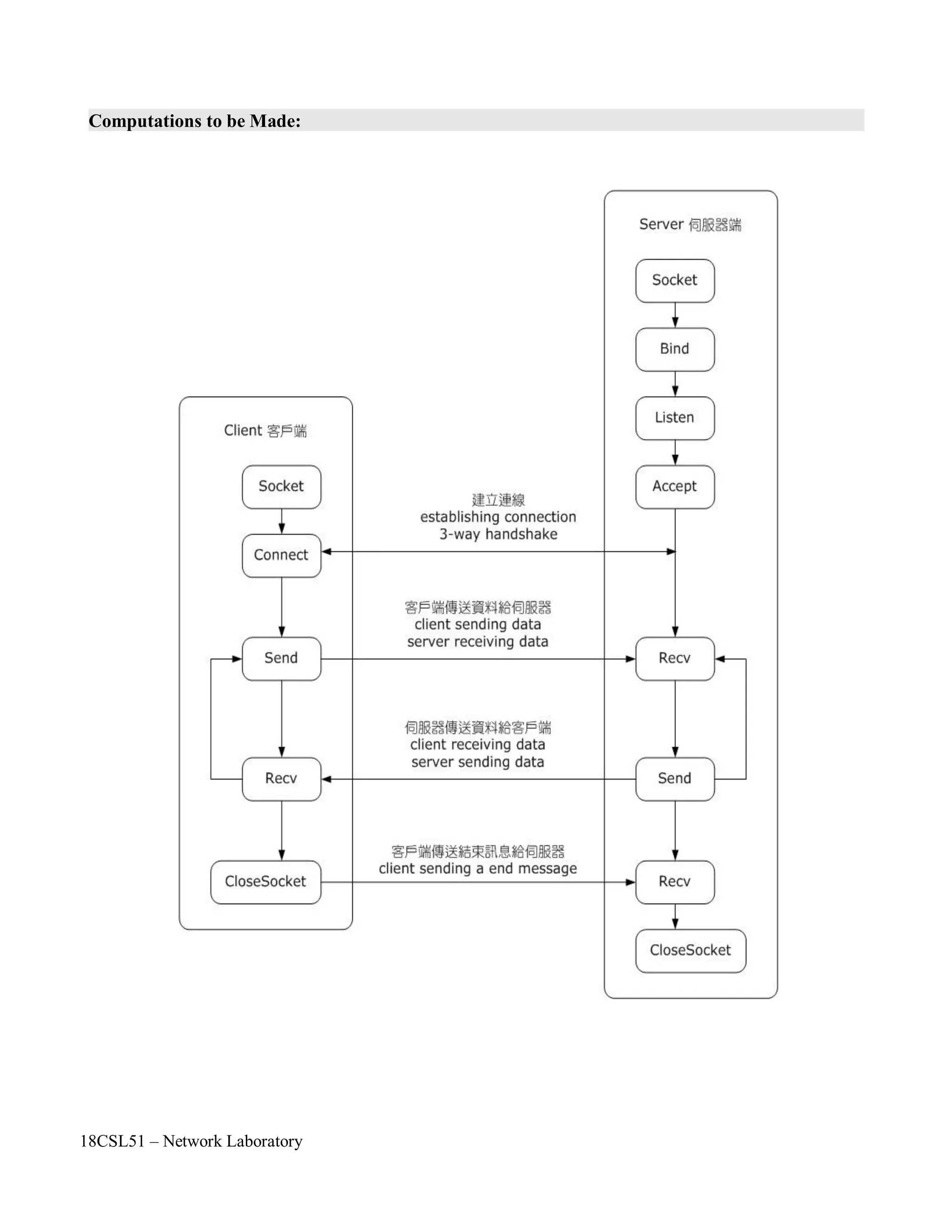
Step 1: First include the necessary header files.
Step 2: Create a socket by using socket() API function.
Step 3: Check with the error code. [0 represents success, while -1 represents an error]
Step 4: Specify the socket address values such as internet address family, server IP address and
Port number.
Step 5: Connect to the server by using connect() API function.
Step 6: Check with the error code. [0 represents success, while -1 represents anerror]
Step 7: Close the socket by using close() API function.
Course Code : 18CSL51
Course Name : Network Laboratory
Experiment Number 15
Name of the Experiment : TCP/IP Client Side Socket Operations](https://image.slidesharecdn.com/18csl51-networklabmanual-220519112438-6d77913b/75/18CSL51-Network-Lab-Manual-pdf-112-2048.jpg)


![18CSL51 – Network Laboratory
Objectives of the Experiment / Practical work:
Resource Required:
Step-wise Experimental Procedure:
On completion of the experiment the students will be able to
• To understand the various server side socket operations in TCP/IP model.
• To establish client – server connection for the communication.
• OS : Linux
• C Compiler : cc or gcc
• Text Editor : vi or gedit
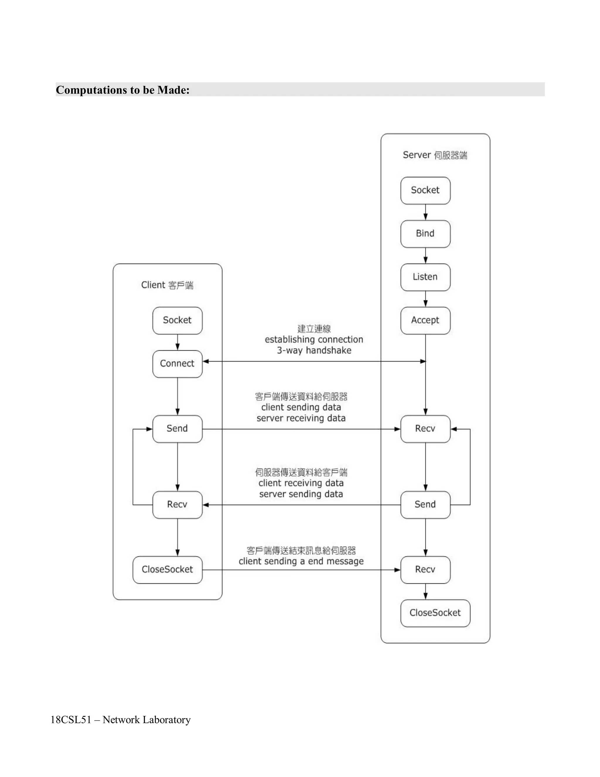
Client:
Step 1: First include the necessary header files.
Step 2: Create a socket by using socket() API function.
Step 3: Check with the error code. [0 represents success, while -1 represents an error]
Step 4: Specify the socket address values such as internet address family, server IP address and
Port number.
Step 5: Connect to the server by using connect() API function.
Step 6: Check with the error code. [0 represents success, while -1 represents anerror]
Step 7: Close the socket by using close() API function.
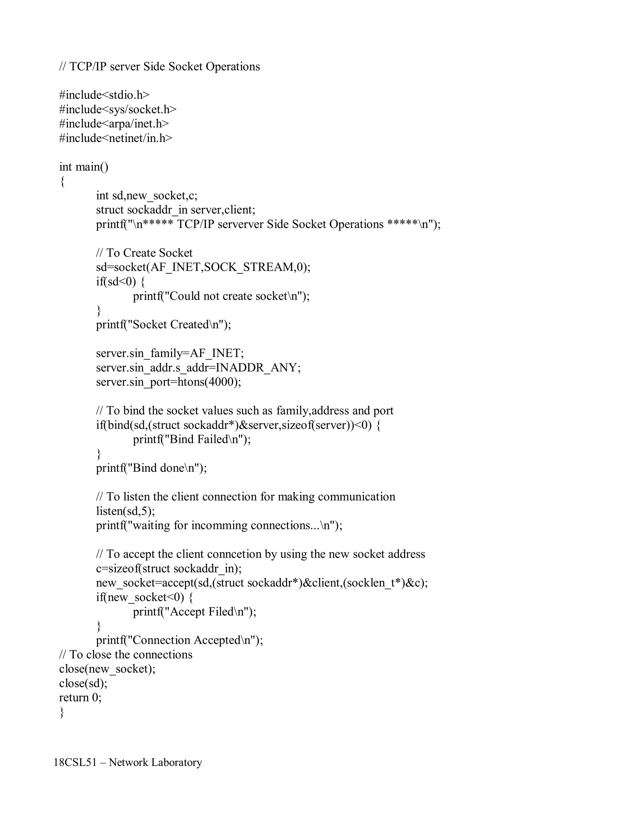
Server:
Step 1: First include the necessary header files.
Step 2: Create a socket by using socket() API function.
Step 3: Check with the error code. [0 represents success, while -1 represents an error]
Step 4: Specify the socket address values such as internet address family, server IP address and
Port number.
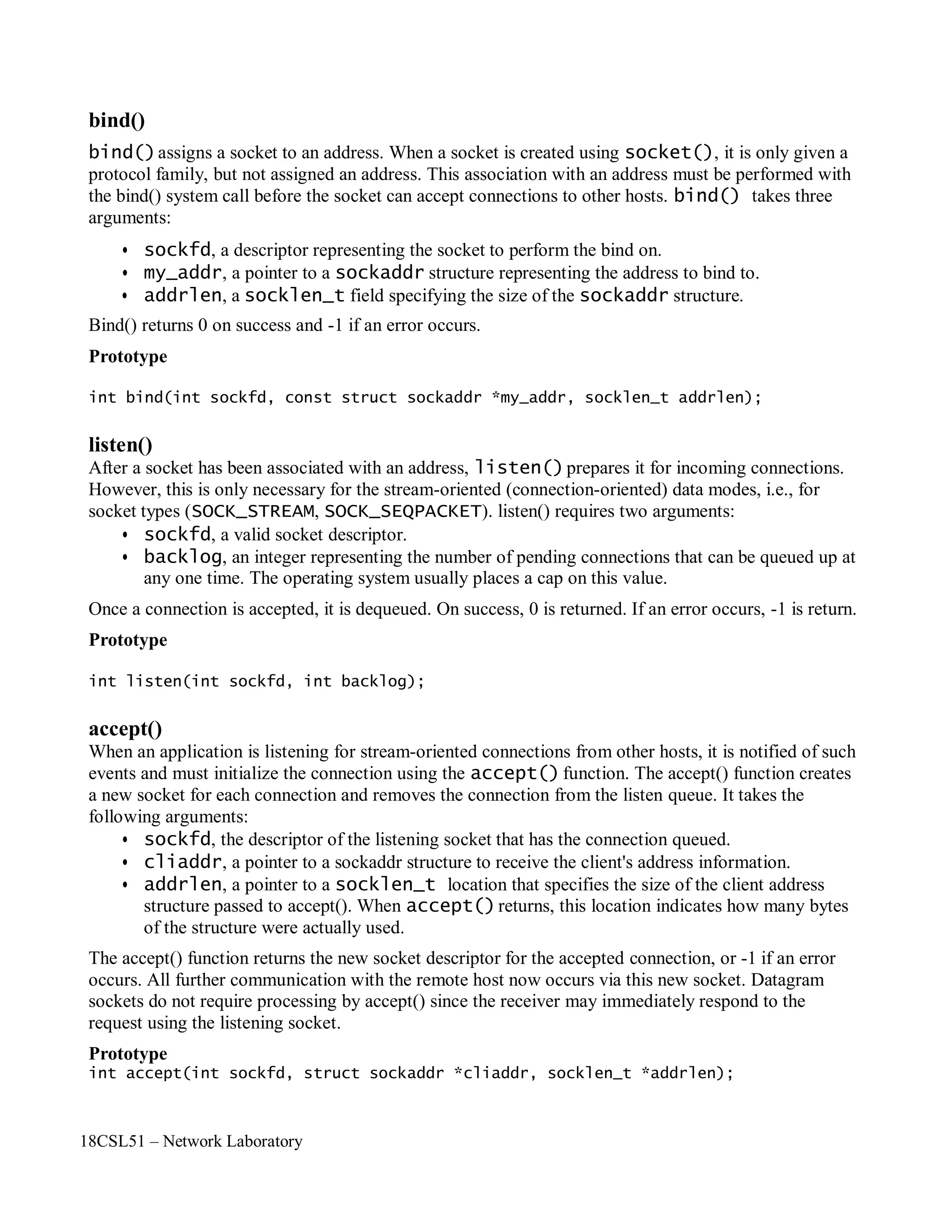
Step 5: Bind the the socket to an IP address and port address by using bind() API function. [ It
needs a sockaddr_in structure to connect function.]
Step 6: Check with the error code. [0 represents success, while -1 represents anerror]
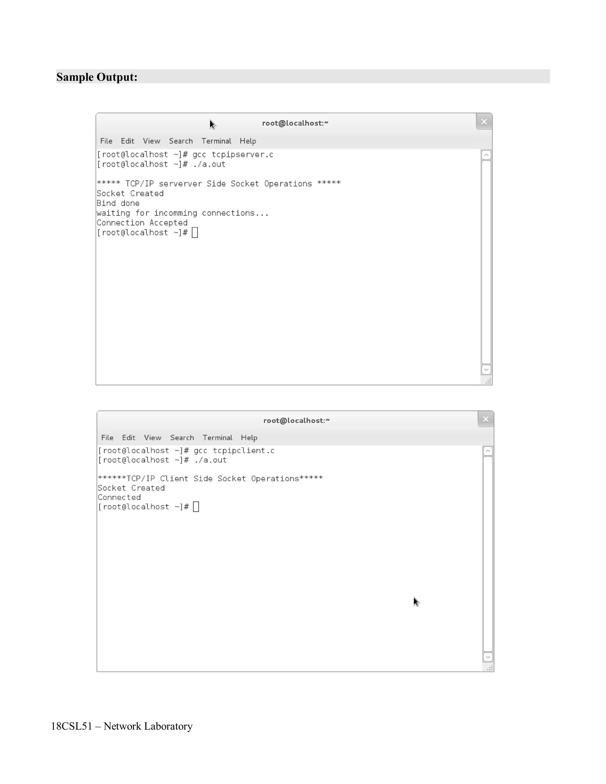
Step 7: Next listen for connections from the client by using listen() API function.
Step 8: Create a new socket for each connection & removes the connection from listen queue.
Step 9: Close the sockets by using close() API function.
Course Code : 18CSL51
Course Name : Network Laboratory
Experiment Number 16
Name of the Experiment : TCP/IP Server Side Socket Operations](https://image.slidesharecdn.com/18csl51-networklabmanual-220519112438-6d77913b/75/18CSL51-Network-Lab-Manual-pdf-118-2048.jpg)

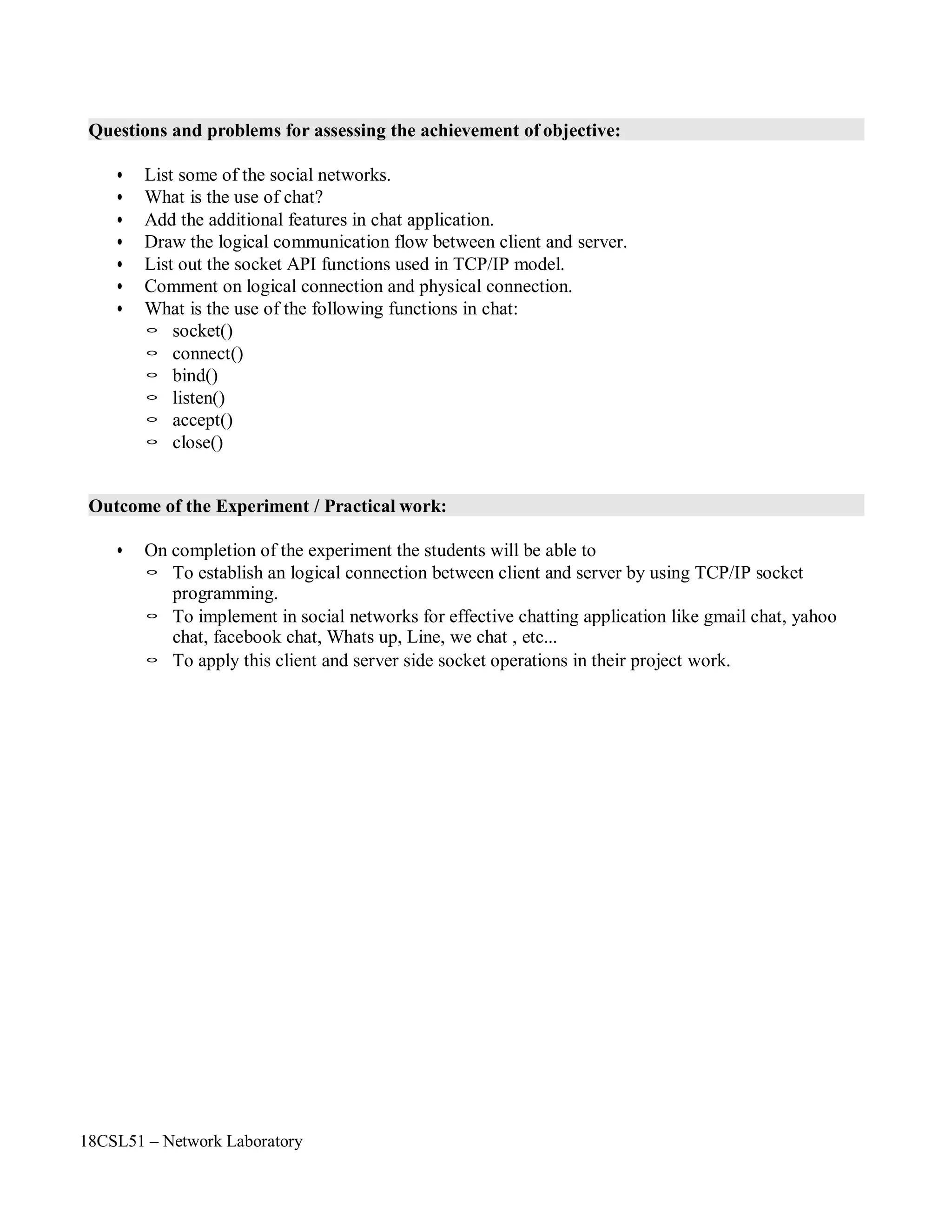
![18CSL51 – Network Laboratory
Objectives of the Experiment / Practical work:
Resource Required:
Step-wise Experimental Procedure:
On completion of the experiment the students will be able to
• To understand the concept of chatting application using TCP/IP model.
• To establish client – server connection for the communication.
• OS : Linux
• C Compiler : cc or gcc
• Text Editor : vi or gedit
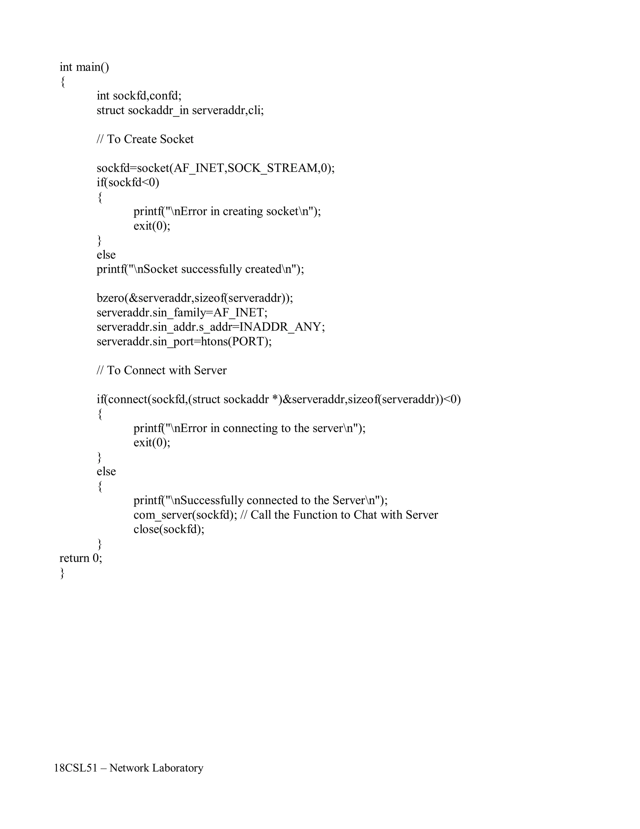
Client:
Step 1: First include the necessary header files.
Step 2: Write a function to communicate with server
void com_server(int sockfd)
Step 3: Create a socket by using socket() API function.
Step 4: Specify the socket address values such as internet address family, server IP address and
Port number.
Step 5: Connect to the server by using connect() API function.
Step 6: Close the socket by using close() API function.
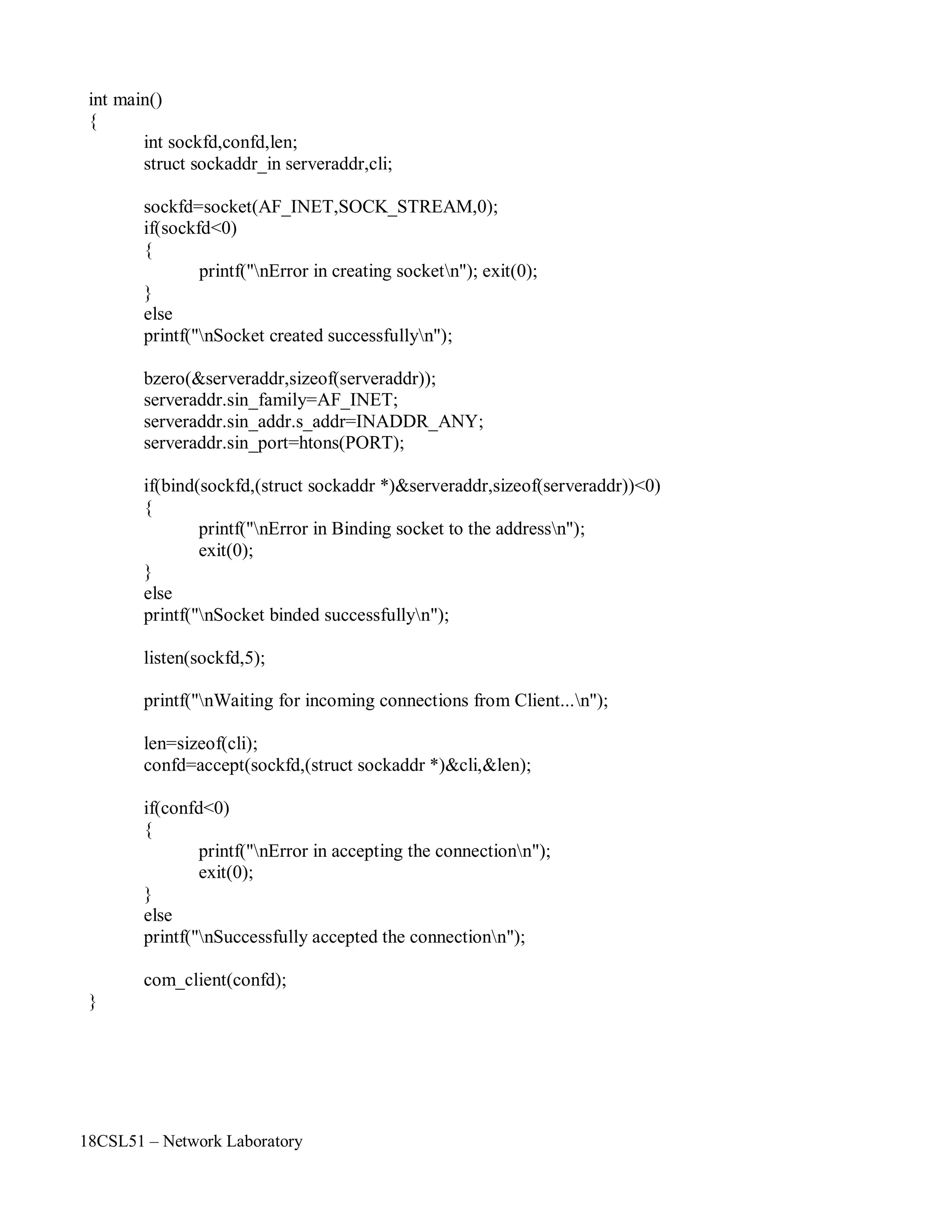
Server:
Step 1: First include the necessary header files.
Step 2: Write a function to communicate with client
void com_client(int sockfd)
Step 3: Create a socket by using socket() API function.
Step 4: Specify the socket address values such as internet address family, server IP address and
Port number.
Step 5: Bind the the socket to an IP address and port address by using bind() API function. [ It
needs a sockaddr_in structure to connect function.]
Step 6: Next listen for connections from the client by using listen() API function.
Step 7: Create a new socket for each connection & removes the connection from listen queue by
using accept() API function.
Step 8: Close the sockets by using close() API function.
Course Code : 18CSL51
Course Name : Network Laboratory
Experiment Number 17
Name of the Experiment : Client Server Application For Chat](https://image.slidesharecdn.com/18csl51-networklabmanual-220519112438-6d77913b/75/18CSL51-Network-Lab-Manual-pdf-126-2048.jpg)

![18CSL51 – Network Laboratory
Program:
#include<stdio.h>
#include<netinet/in.h>
#include<sys/socket.h>
#include<netinet/in.h> //sockaddr
#include<string.h>
#include<stdlib.h>
#define BUFFER_SIZE 256
#define PORT 57323
// Chat Application Function - To communicate with server
void com_server(int sockfd)
{
char snd[BUFFER_SIZE]; // To Send Data
char rcv[BUFFER_SIZE]; // To Receive Data
int bytes_rcv;
for(;;)
{
bzero(snd,BUFFER_SIZE); // To clear the buffer
printf("nEnter the Data : ");
fgets(snd,255,stdin); // To Read Data from the user
write(sockfd,snd,sizeof(snd)); // To Send Data
read(sockfd,rcv,sizeof(rcv)); // To Receive Data
bytes_rcv=strlen(rcv); // To Calculate Number of Bytes Received
printf("nbytes received = %d bytesnData received from Server : %s",bytes_rcv-1,rcv);
if((strncmp(rcv,"bye",3))==0) // To Close the connection
{
bzero(rcv,BUFFER_SIZE);
printf("nConnection closed...n");
break;
}
bzero(rcv,BUFFER_SIZE);
}
}](https://image.slidesharecdn.com/18csl51-networklabmanual-220519112438-6d77913b/75/18CSL51-Network-Lab-Manual-pdf-131-2048.jpg)
![18CSL51 – Network Laboratory
#include<stdio.h>
#include<netinet/in.h>
#include<sys/socket.h>
#include<netinet/in.h> //sockaddr
#include<string.h>
#include<stdlib.h>
#define BUFFER_SIZE 256
#define PORT 57323
// Chat Application Function - To communicate with Client
void com_client(int sockfd)
{
char snd[BUFFER_SIZE];
char rcv[BUFFER_SIZE];
int bytes_rcv;
for(;;)
{
bzero(rcv,BUFFER_SIZE);
read(sockfd,rcv,sizeof(rcv));
bytes_rcv=strlen(rcv);
printf("nbytes received = %d bytesnData received from Client : %s",bytes_rcv-1,rcv);
bzero(snd,BUFFER_SIZE);
printf("nEnter the Data : ");
fgets(snd,255,stdin);
write(sockfd,snd,sizeof(snd));
if((strncmp(snd,"bye",3))==0)
{
bzero(snd,BUFFER_SIZE);
printf("nConnection closed...n");
break;
}
}
}](https://image.slidesharecdn.com/18csl51-networklabmanual-220519112438-6d77913b/75/18CSL51-Network-Lab-Manual-pdf-133-2048.jpg)
![18CSL51 – Network Laboratory
Objectives of the Experiment / Practical work:
Resource Required:
Step-wise Experimental Procedure:
On completion of the experiment the students will be able to
• To know the various flow control mechanism such as stop and wait protocol and sliding
window protocol.
• To send packets by using Go – Back – N Method.
• OS : Linux
• C Compiler : cc or gcc
• Text Editor : vi or gedit
Client:
Step 1: First include the necessary header files.
Step 2: Set the Window Size[WIN] as 5 and Message Length [MSGLEN] as 10
Step 3: Create a socket by using socket() API function.
Step 4: Check with the error code. [0 represents success, while -1 represents an error]
Step 5: Specify the socket address values such as internet address family, IP and Port number.
Step 6: Connect to the server by using connect() API function.
Step 7: Check with the error code. [0 represents success, while -1 represents anerror]
Step 8: Read the data from the user by using an array.
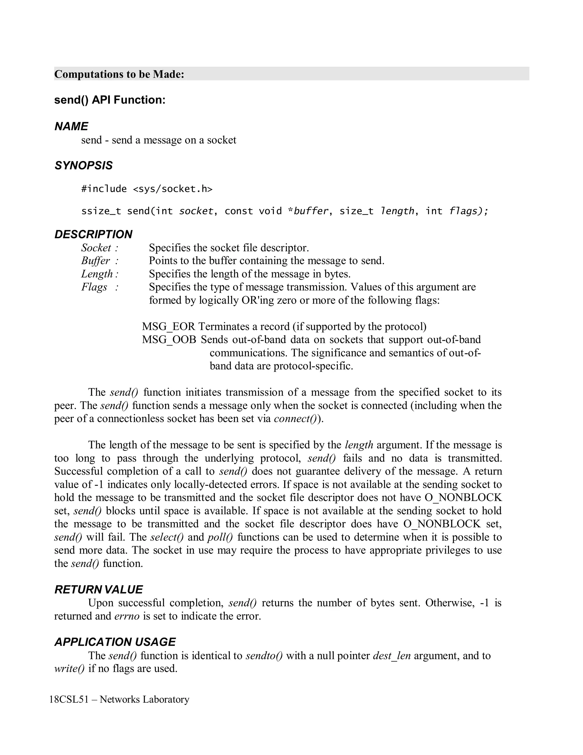
Step 9: Send the data to the server by using send() API function.
Step 10: Receive the acknowledgment [ACK] from the server by using read() API function.
Step 11: Close the socket by using close() API function.
Server:
Step 1: Create a socket by using socket() API function.
Step 2: Check with the error code. [0 represents success, while -1 represents an error]
Step 3: Specify the socket address values such as internet address family, IP and Port number.
Step 4: Bind the the socket to an IP address and port address by using bind() API function.
Step 5: Check with the error code. [0 represents success, while -1 represents anerror]
Step 6: Next listen for connections from the client by using listen() API function.
Step 7: Create a new socket for each connection & removes the connection from listen queue by
using accept() API function..
Step 8: Receive the data from the client by using read() API function.
Step 9: Send the Acknowledgment [ACK] by using send() API finction.
Step 10: Close the sockets by using close() API function.
Course Code : 18CSL51
Course Name : Network Laboratory
Experiment Number 18
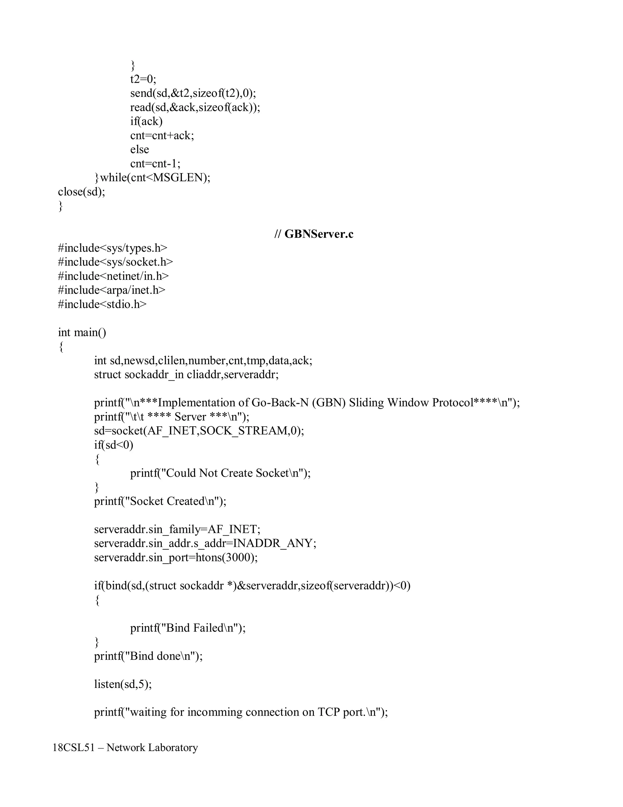
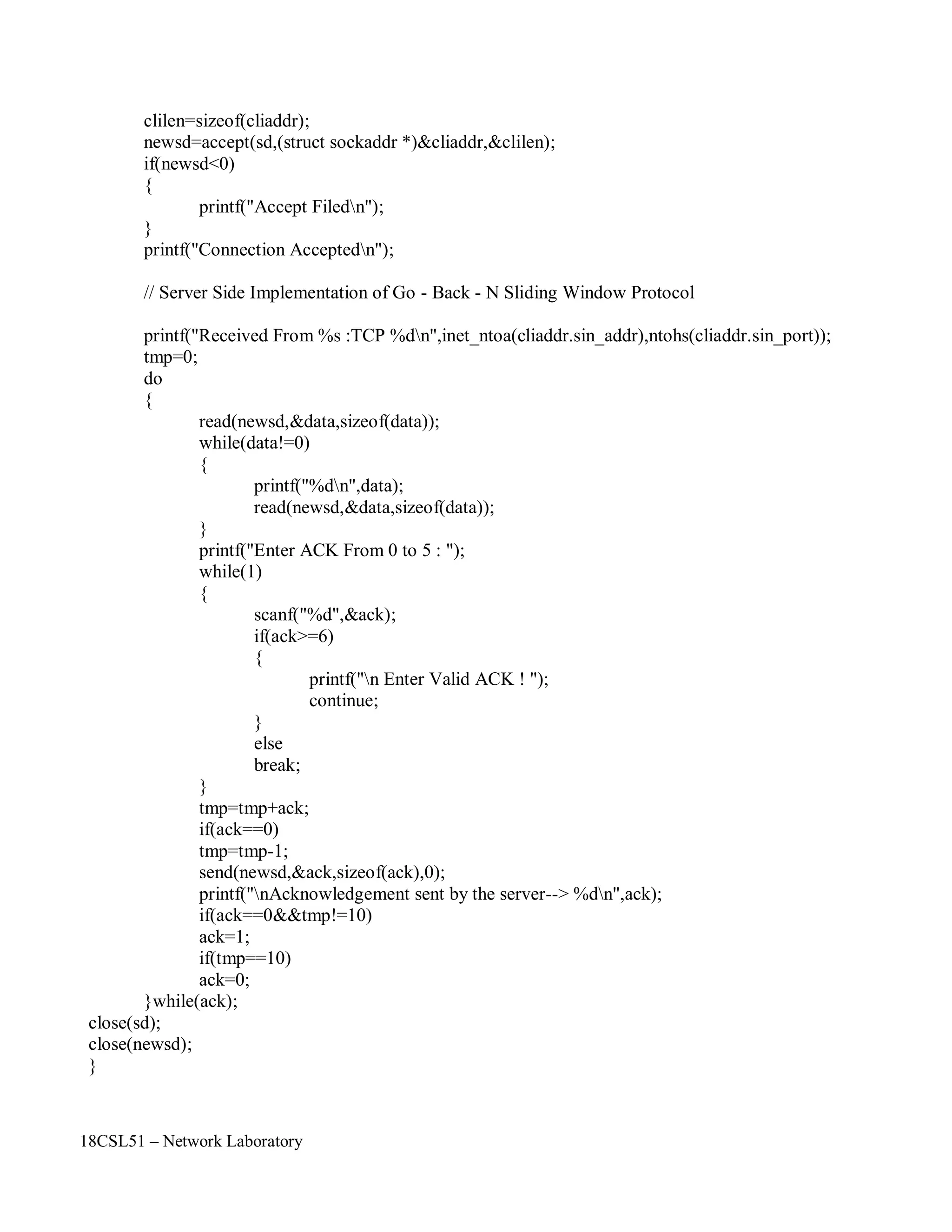
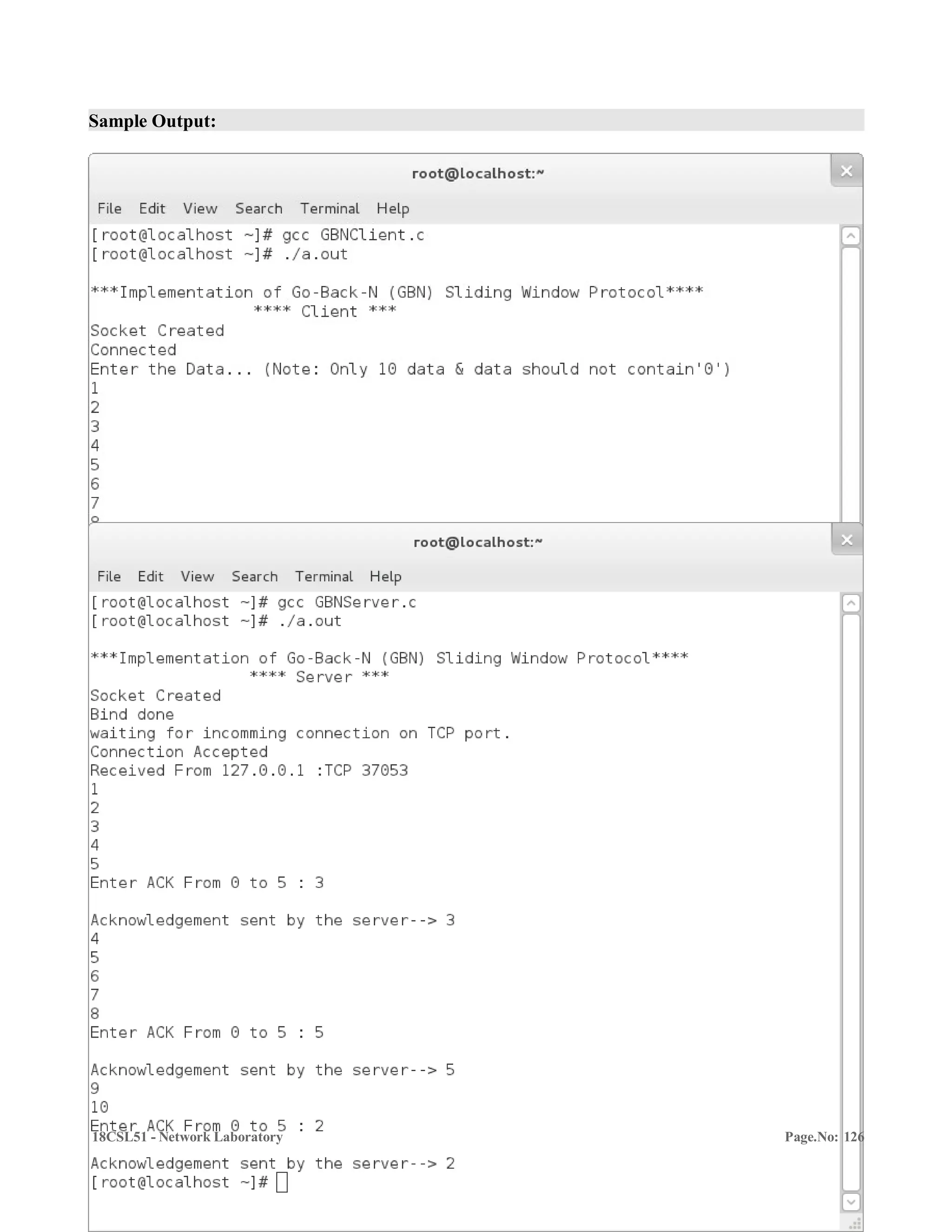
Name of the Experiment : Implementation of Go – Back – N Sliding Window Protocol](https://image.slidesharecdn.com/18csl51-networklabmanual-220519112438-6d77913b/75/18CSL51-Network-Lab-Manual-pdf-136-2048.jpg)
![18CSL51 – Network Laboratory
Program
// GBNClient.c
#include<sys/socket.h>
#include<sys/types.h>
#include<netinet/in.h>
#include<arpa/inet.h>
#include<stdio.h>
#define WIN 5
#define MSGLEN 10
int main()
{
int sd,t2,msg[MSGLEN],cnt=0,ack=0,j;
struct sockaddr_in localaddr;
printf("n***Implementation of Go-Back-N (GBN) Sliding Window Protocol****n");
printf("tt **** Client ***n");
sd=socket(AF_INET,SOCK_STREAM,0);
if(sd==-1) {
printf("Could Not Create Socketn");
}
printf("Socket Createdn");
localaddr.sin_family=AF_INET;
localaddr.sin_addr.s_addr=INADDR_ANY;
localaddr.sin_port=htons(3000);
if(connect(sd,(struct sockaddr *)&localaddr,sizeof(localaddr))<0) {
printf("Could not Connectedn");
}
printf("Connectedn");
// Client Side Implementation of Go - Back - N Sliding Window Protocol
printf("Enter the Data... (Note: Only 10 data & data should not contain'0')n");
for(j=0;j<MSGLEN;j++)
scanf("%d",&msg[j]);
cnt=0;
do {
printf("Sending datan");
for(j=cnt;j<WIN+cnt;j++)
if(j<MSGLEN) {
t2=msg[j];
send(sd,&t2,sizeof(t2),0);
printf("%dn",msg[j]);](https://image.slidesharecdn.com/18csl51-networklabmanual-220519112438-6d77913b/75/18CSL51-Network-Lab-Manual-pdf-141-2048.jpg)
![Objectives of the Experiment / Practical work:
Resource Required:
Step-wise Experimental Procedure:
On completion of the experiment the students will be able to
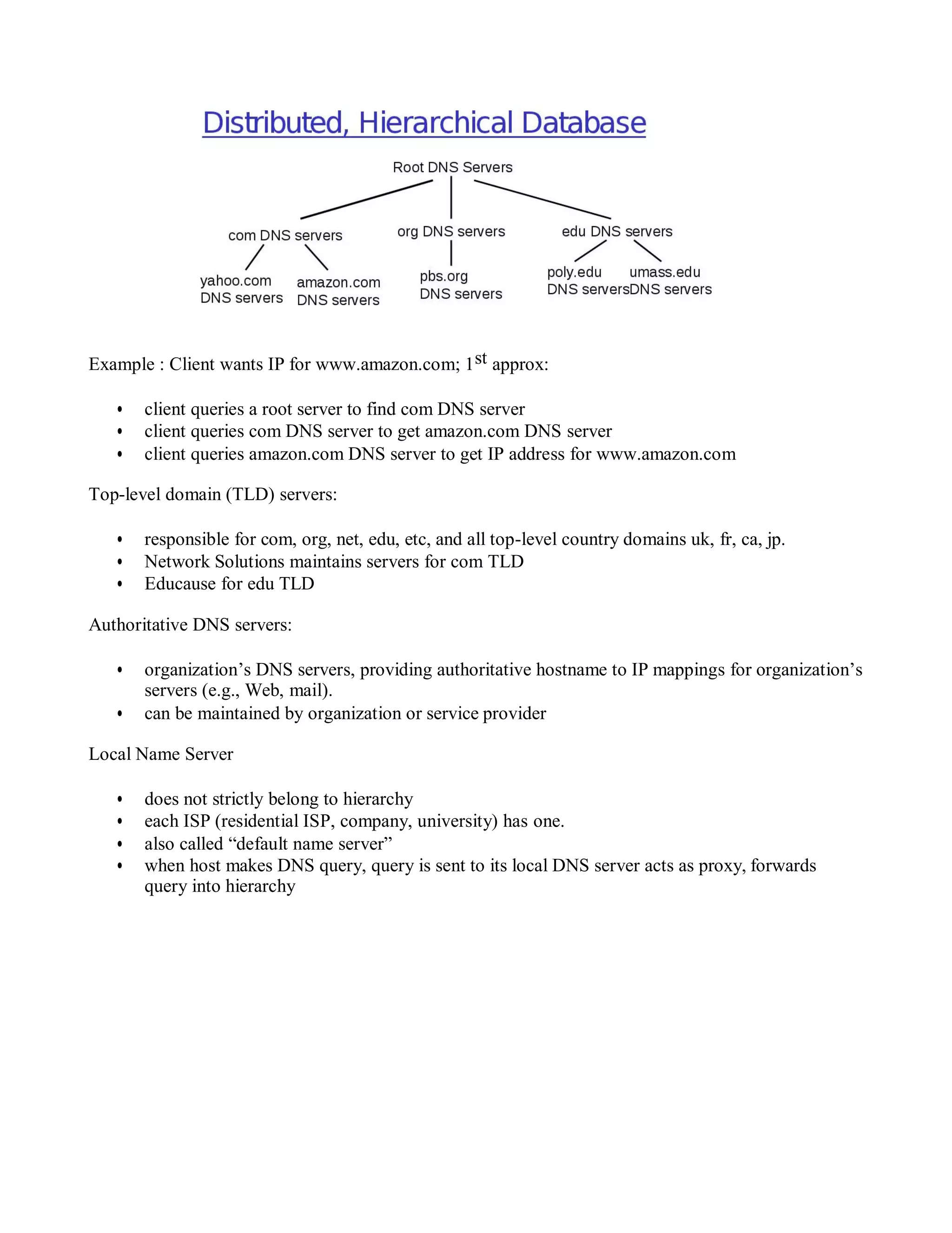
• To understand the usage of DNS protocol.
• To contact the given DNS server to resolve a given hostname.
• OS : Linux
• C Compiler : cc or gcc
• Text Editor : vi or gedit
Client:
Step 1: First include the necessary header files.
Step 2: Create a socket by using socket() API function.
Step 3: Check with the error code. [0 represents success, while -1 represents an error]
Step 4: Specify the socket address values such as internet address family, server IP address andPort.
Step 5: Connect to the server by using connect() API function.
Step 6: Check with the error code. [0 represents success, while -1 represents an error]
Step 7: Read the hostname from the user and sent to the server by using send() API function.
Step 8: Receive the IP address fro given hostname from the DNSServer by using recv() API.
Step 9: Close the socket by using close() API function.
Server:
Step 1: First include the necessary header files.
Step 2: Create a socket by using socket() API function.
Step 3: Check with the error code. [0 represents success, while -1 represents an error]
Step 4: Specify the socket address values such as internet address family, server IP address andPort..
Step 5: Bind the the socket to an IP address and port address by using bind() API function.
Step 6: Check with the error code. [0 represents success, while -1 represents anerror]
Step 7: Next listen for connections from the client by using listen() API function.
Step 8: Create a new socket for each connection & removes the connection from listen queueby
using accept() API function.
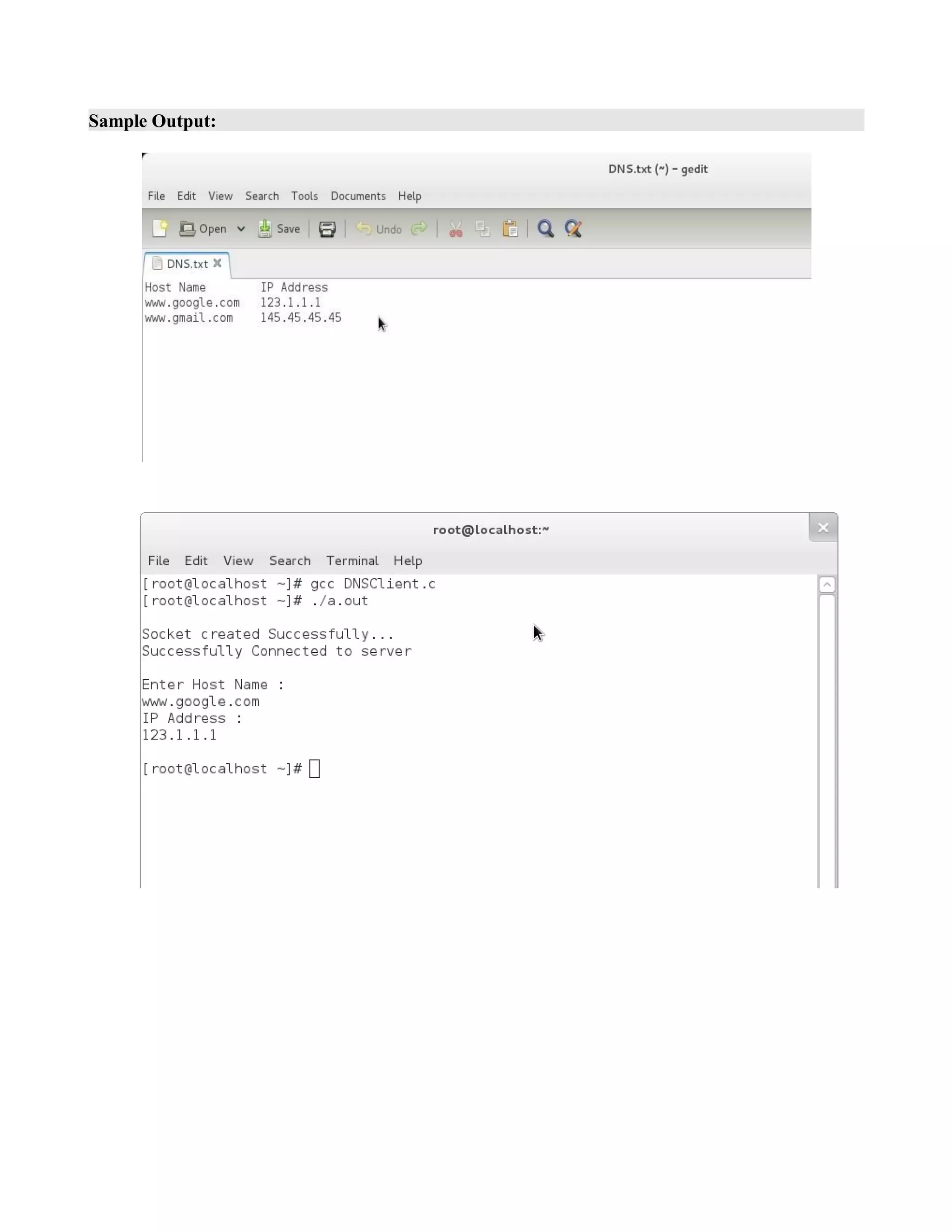
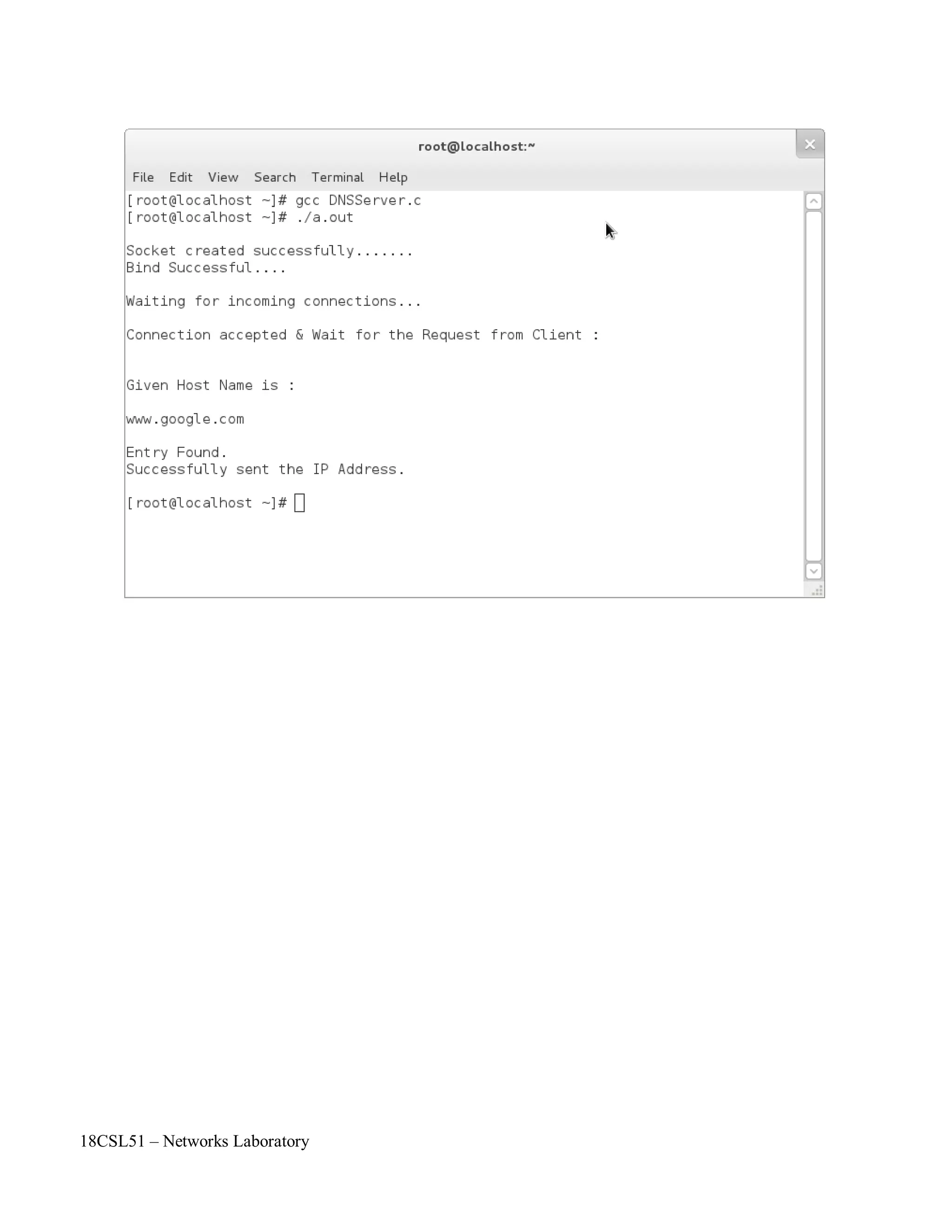
Step 9: Read the hostname from the client by using recv() API function.
Step 10: By using FILE concept open the file (DNS.txt) and find the corresponding IP address of
the hostname by usinf strcmp() function.
Step 11: Send the IP address of the hostname by using send() API function.
Step 12: Close the sockets by using close() API function.
Course Code : 18CSL51
Course Name : Network Laboratory
Experiment Number 19
Name of the Experiment : Implementation of DNS Protocol](https://image.slidesharecdn.com/18csl51-networklabmanual-220519112438-6d77913b/75/18CSL51-Network-Lab-Manual-pdf-145-2048.jpg)


![Program:
#include<stdio.h>
#include<string.h>
#include<sys/socket.h>
#include<arpa/inet.h>
int main()
{
int sd;
struct sockaddr_in server;
char message[1000] , server_reply[2000];
sd = socket(AF_INET , SOCK_STREAM , 0);
if (sd == -1)
{
printf("Could not create socket");
}
puts("nSocket created Successfully...");
server.sin_addr.s_addr = inet_addr("127.0.0.1");
server.sin_family = AF_INET;
server.sin_port = htons(5000);
if (connect(sd , (struct sockaddr *)&server , sizeof(server)) < 0)
{
perror("connect failed. Error");
return 1;
}
puts("Successfully Connected to servern");
printf("Enter Host Name :n");
scanf("%s" , message);
//Send some data
if( send(sd , message , strlen(message) , 0) < 0)
{
puts("Send failed");
return 1;
}
//Receive a reply from the server
if( recv(sd , server_reply , 2000 , 0) < 0) {
puts("recv failed");
}
puts("IP Address :");
puts(server_reply);
printf("n");
close(sd);
return 0;
}](https://image.slidesharecdn.com/18csl51-networklabmanual-220519112438-6d77913b/75/18CSL51-Network-Lab-Manual-pdf-150-2048.jpg)
![#include<string.h> //strlen
#include<sys/socket.h>
#include<arpa/inet.h> //inet_addr
#include<unistd.h> //write
#include<stdio.h>
int main()
{
int socket_desc , client_sock , c , read_size;
struct sockaddr_in server , client;
char client_message[2000],message[1000];
//Create socket
socket_desc = socket(AF_INET , SOCK_STREAM , 0);
if (socket_desc == -1)
{
printf("Could not create socket");
}
printf("nSocket created successfully ......n");
//Prepare the sockaddr_in structure
server.sin_family = AF_INET;
server.sin_addr.s_addr = INADDR_ANY;
server.sin_port = htons(5000);
//Bind
if( bind(socket_desc,(struct sockaddr *)&server , sizeof(server)) < 0)
{
//print the error message
perror("binding failed. ....n");
return 1;
}
puts("Bind Successful... n");
//Listen
listen(socket_desc , 3);
//Accept and incoming connection
puts("Waiting for incoming connections ..");
c = sizeof(struct sockaddr_in);
//accept connection from an incoming client
client_sock = accept(socket_desc, (struct sockaddr *)&client, (socklen_t*)&c);
if (client_sock < 0)
{
perror("accept failed");
return 1;
}
puts("nConnection accepted & Wait for the Request from Client :n");](https://image.slidesharecdn.com/18csl51-networklabmanual-220519112438-6d77913b/75/18CSL51-Network-Lab-Manual-pdf-151-2048.jpg)
![if( recv(client_sock , client_message , 2000 , 0) < 0)
{
puts("recv failed");
}
puts("nGiven Host Name is :n");
puts(client_message);
FILE *fp;
char ip[100],temp[100];
fp=fopen("DNS.txt","r");
if(fp==NULL)
printf("Error in Opening File");
else
{
while(!feof(fp))
{
fscanf(fp,"%s",temp);
if(strcmp(client_message,temp)==0)
break;
}
if(strcmp(client_message,temp)==0)
{
}
else
{
}
}
fscanf(fp,"%s",ip);
printf("nEntry Found.");
printf("nEntry Not Found.");
strcpy(ip,"Invalid Host Name..");
if(send(client_sock , ip , strlen(ip) , 0) < 0)
{
puts("Send failed");
return 1;
}
puts("nSuccessfully sent the IP Address.n");
return 0;
}](https://image.slidesharecdn.com/18csl51-networklabmanual-220519112438-6d77913b/75/18CSL51-Network-Lab-Manual-pdf-152-2048.jpg)
![18CSL51 – Networks Laboratory
Objectives of the Experiment / Practical work:
Resource Required:
Step-wise Experimental Procedure:
On completion of the experiment the students will be able to
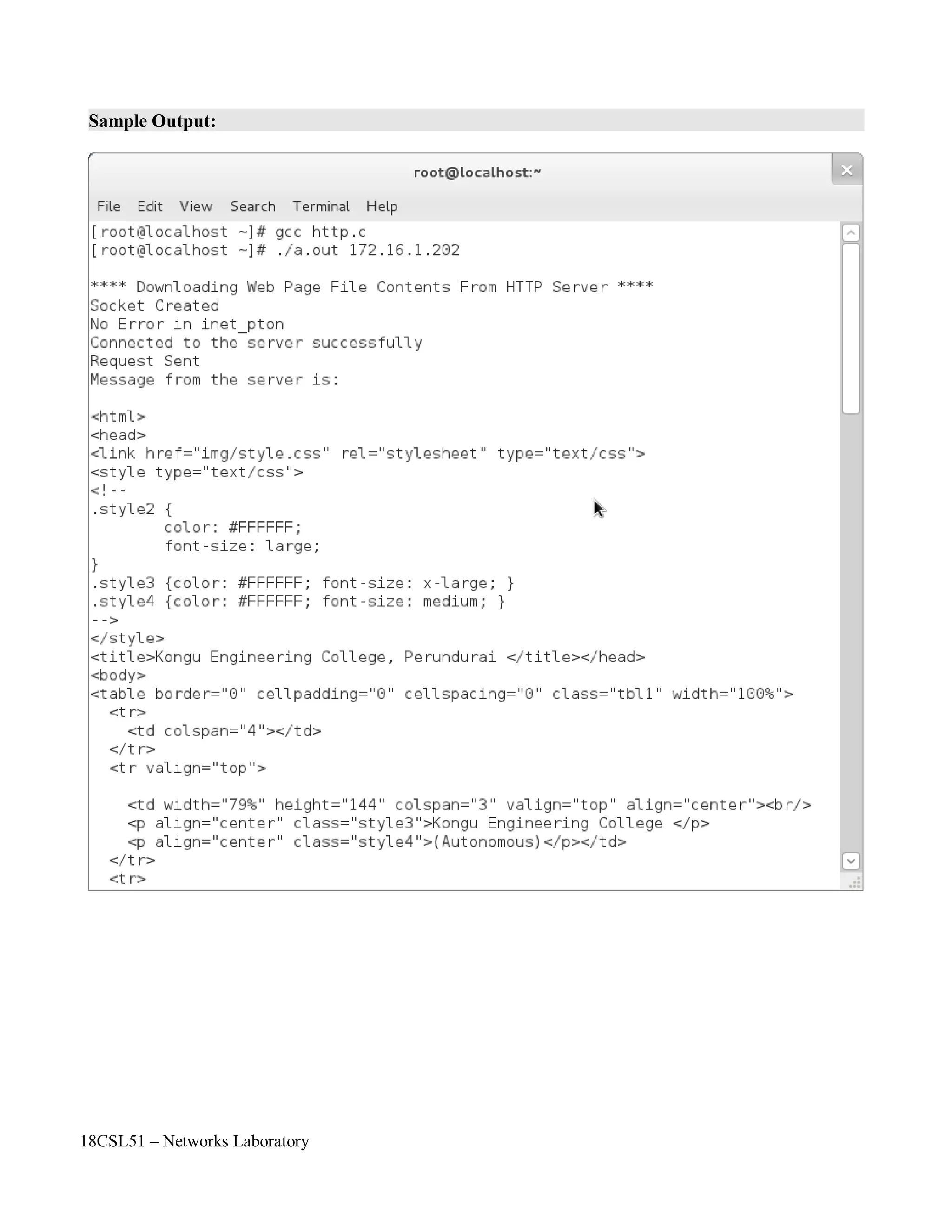
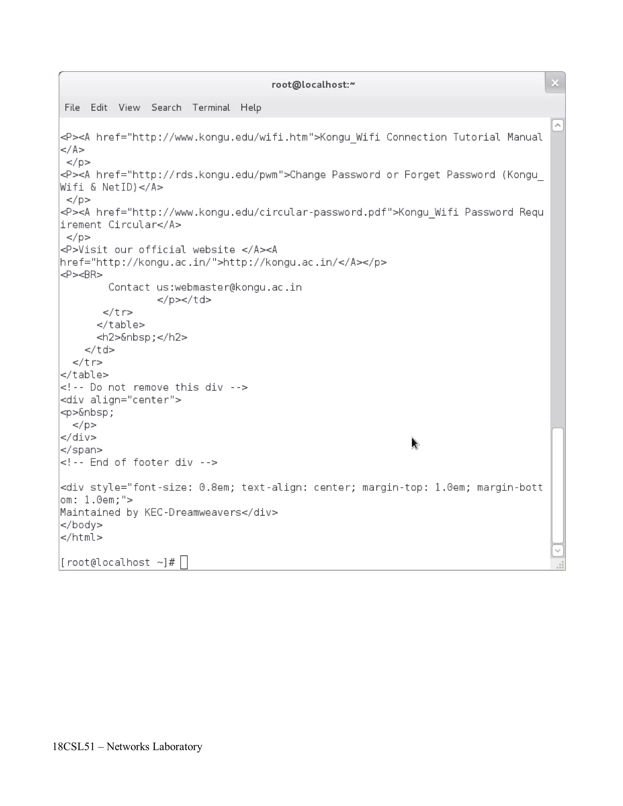
• To download a web page file contents from the internet by using HTTP server.
• To send an request to the server and receive reply from the server.
• OS : Linux
• C Compiler : cc or gcc
• Text Editor : vi or gedit
Client:
Step 1: First include the necessary header files.
Step 2: Use command line arguments to give an server IP address.
int main( int argc, char *arv[])
Step 3: Create a socket by using socket() API function.
Step 4: Get the Server IP address in command line and convert text address into network byte
order by using inet_pton() funtion.
Step 5: Check with the error code. [0 represents success, while -1 represents an error]
Step 6: Specify the socket address values such as internet address family and Port number as 80.
Step 7: Connect to the server by using connect() API function.
Step 8: Check with the error code. [0 represents success, while -1 represents an error]
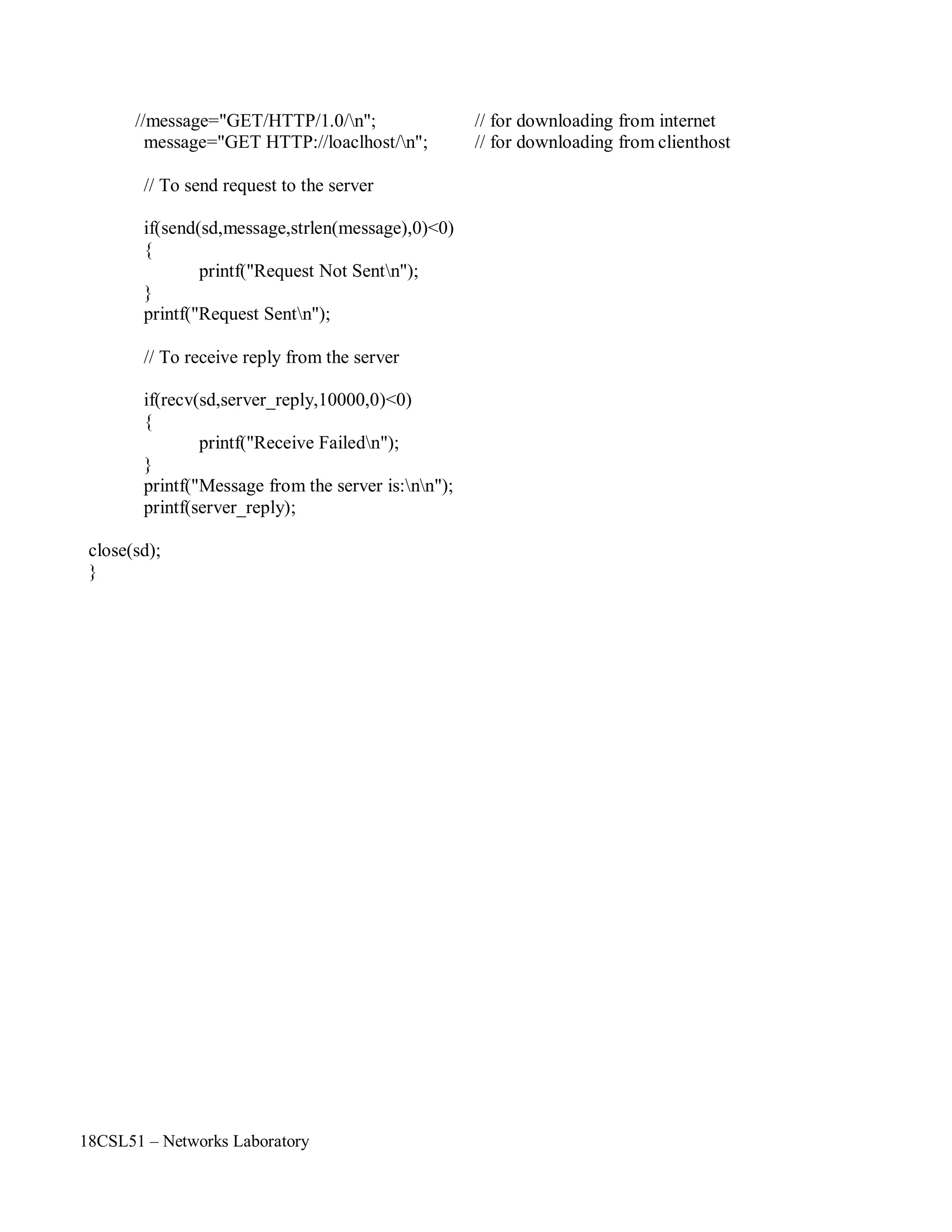
Step 9: Send an request message as “GET HTTP://localhost/” by using send() API function.
Step 10: Receive the reply from the server by using recv() API function.
Step 11: Display the received file contents by using an array called server_reply[10000].
Step 12: Close the socket by using close() API function.
Course Code : 18CSL51
Course Name : Network Laboratory
Experiment Number 20
Name of the Experiment : Downloading Web Page File Contents From HTTP Server](https://image.slidesharecdn.com/18csl51-networklabmanual-220519112438-6d77913b/75/18CSL51-Network-Lab-Manual-pdf-155-2048.jpg)
![18CSL51 – Networks Laboratory
recv() API Function:
NAME
recv - receive a message from a connected socket
SYNOPSIS
#include <sys/socket.h>
ssize_t recv(int socket, void *buffer, size_t length, int flags);
DESCRIPTION
The recv() function receives a message from a connection-mode or connectionless-mode socket.
It is normally used with connected sockets because it does not permit the application to retrieve
the source address of received data. The function takes the following arguments:
socket : Specifies the socket file descriptor.
Buffer : Points to a buffer where the message should be stored.
Length : Specifies the length in bytes of the buffer pointed to by the buffer argument.
Flags : Specifies the type of message reception. Values of this argument are formed
by logically OR'ing zero or more of the following values:
MSG_PEEK
Peeks at an incoming message. The data is treated as unread and the next recv()
or similar function will still return this data.
MSG_OOB
Requests out-of-band data. The significance and semantics of out-of-band data
are protocol-specific.
MSG_WAITALL
Requests that the function block until the full amount of data requested can be
returned. The function may return a smaller amount of data if a signal is caught,
if the connection is terminated, if MSG_PEEK was specified, or if an error is
pending for the socket.
The recv() function returns the length of the message written to the buffer pointed to by the
buffer argument. For message-based sockets such as SOCK_DGRAM and
SOCK_SEQPACKET, the entire message must be read in a single operation. If a message is too
long to fit in the supplied buffer, and MSG_PEEK is not set in the flags argument, the excess
bytes are discarded. For stream-based sockets such as SOCK_STREAM, message boundaries are
ignored. In this case, data is returned to the user as soon as it becomes available, and no data is
discarded. If the MSG_WAITALL flag is not set, data will be returned only up to the end of the
first message. If no messages are available at the socket and O_NONBLOCK is not set on the
socket's file descriptor, recv() blocks until a message arrives. If no messages are available at the
socket and O_NONBLOCK is set on the socket's file descriptor, recv() fails and sets errno to
[EAGAIN] or [EWOULDBLOCK].
RETURN VALUE
Upon successful completion, recv() returns the length of the message in bytes. If no messages are
available to be received and the peer has performed an orderly shutdown, recv() returns 0.
Otherwise, -1 is returned and errno is set to indicate the error.
APPLICATION USAGE
The recv() function is identical to recvfrom() with a zero address_len argument, and to
read() if no flags are used.](https://image.slidesharecdn.com/18csl51-networklabmanual-220519112438-6d77913b/75/18CSL51-Network-Lab-Manual-pdf-157-2048.jpg)
![18CSL51 – Networks Laboratory
Program:
// Download a web page file contents from HTTP server
#include<sys/socket.h>
#include<sys/types.h>
#include<netinet/in.h>
#include<arpa/inet.h>
#include<stdio.h>
#include<string.h>
int main(int argc,char*argv[])
{
int sd;
char *message,server_reply[10000];
struct sockaddr_in client;
printf("n**** Downloading Web Page File Contents From HTTP Server ****n");
// To create socket
sd=socket(AF_INET,SOCK_STREAM,0);
if(sd<0)
{
printf("Could not create socketn");
}
printf("Socket Createdn");
client.sin_family=AF_INET;
client.sin_port=htons(80);
// To give user IP address in command line and convert network byte order
if(inet_pton(AF_INET,argv[1],&client.sin_addr.s_addr)<0)
{
printf("INET_PTON ERRORn");
}
printf("No Error in inet_ptonn");
// To connect to the remote server for example www.kongu.edu(172.16.1.202)
if(connect(sd,(struct sockaddr *)&client,sizeof(client))<0)
{
printf("Could not Connectedn");
}
printf("Connected to the server successfullyn");](https://image.slidesharecdn.com/18csl51-networklabmanual-220519112438-6d77913b/75/18CSL51-Network-Lab-Manual-pdf-159-2048.jpg)

The document describes a network laboratory experiment on simulating a star topology using the NS2 simulator. The objectives are to simulate the star topology, understand queuing and packet dropping at routers, and apply the knowledge to measure network performance metrics. The steps include creating nodes and links to form the star topology, generating UDP traffic from two sources to a sink node, and observing packet dropping at the congested link using the nam trace file.


![[PPT] _ UNIT 1 _ COMPLETE.pptx](https://cdn.slidesharecdn.com/ss_thumbnails/pptunit1complete-220516121012-45cab1a3-thumbnail.jpg?width=640&height=640&fit=bounds)


![[PPT] _ Unit 4 _ Engage.pptx](https://cdn.slidesharecdn.com/ss_thumbnails/pptunit4engage-220707115545-9dce3530-thumbnail.jpg?width=640&height=640&fit=bounds)

![[PPT] _ Unit 5 _ Evolve.pptx](https://cdn.slidesharecdn.com/ss_thumbnails/pptunit5evolve-220707120639-5c6df843-thumbnail.jpg?width=640&height=640&fit=bounds)

![[PPT] _ Unit 3 _ Experiment.pptx](https://cdn.slidesharecdn.com/ss_thumbnails/pptunit3experiment-220707114954-1996fe08-thumbnail.jpg?width=640&height=640&fit=bounds)
![[PPT] _ Unit 2 _ 9.0 _ Domain Specific IoT _Home Automation.pdf](https://cdn.slidesharecdn.com/ss_thumbnails/pptunit29-220516115946-098632b6-thumbnail.jpg?width=640&height=640&fit=bounds)
![[PPT] _ Unit 2 _ Complete PPT.pptx](https://cdn.slidesharecdn.com/ss_thumbnails/pptunit2completeppt-220516115836-332a1107-thumbnail.jpg?width=640&height=640&fit=bounds)


