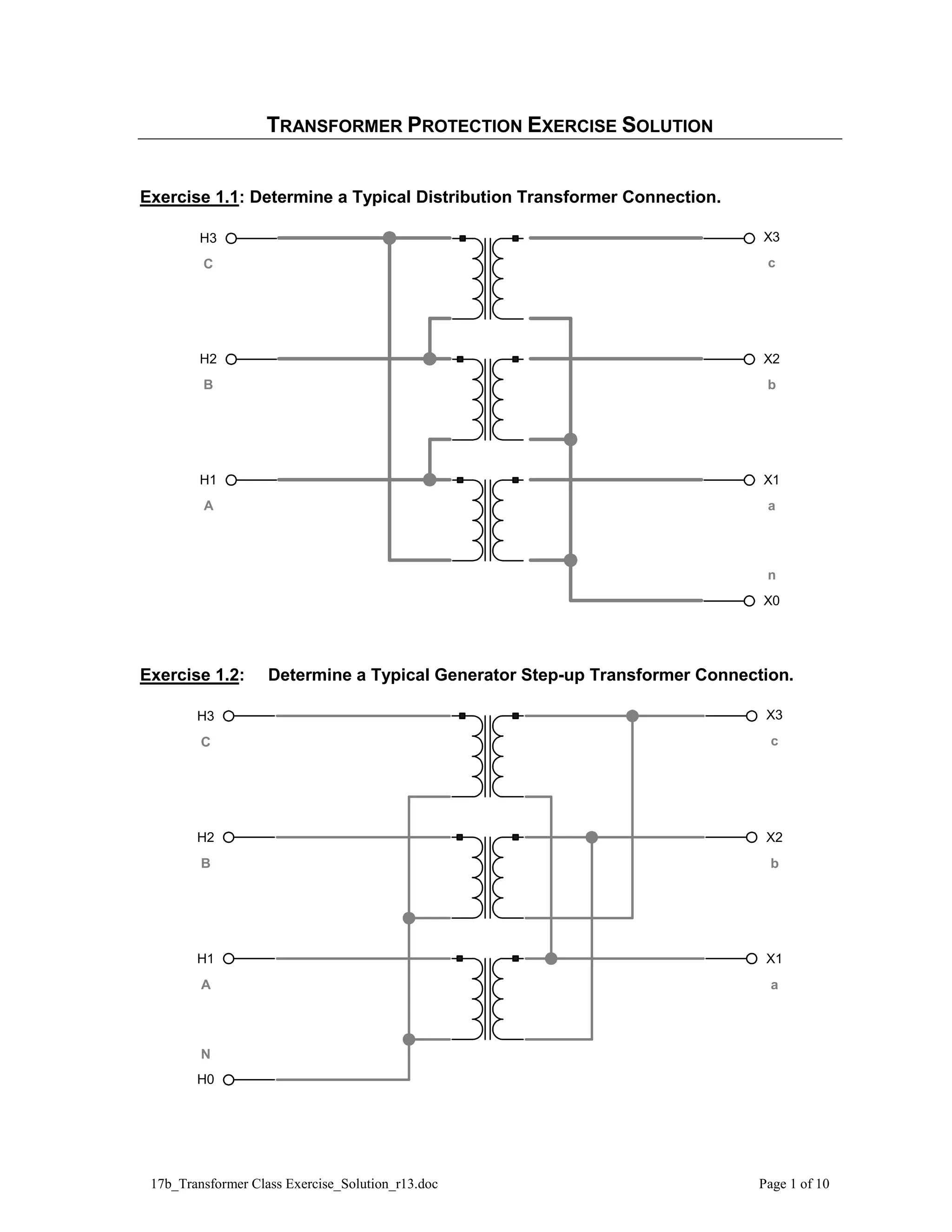
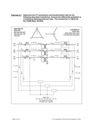
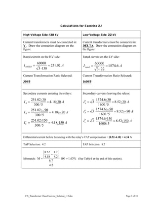
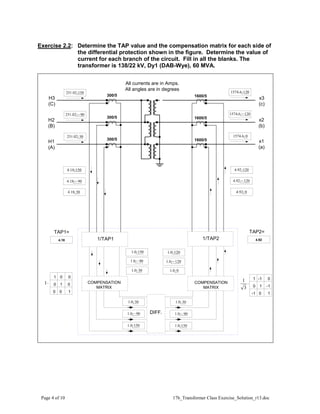
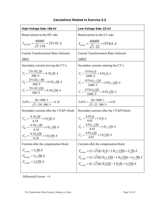
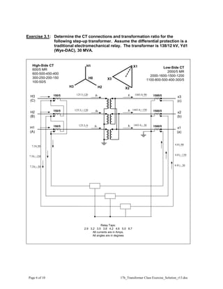
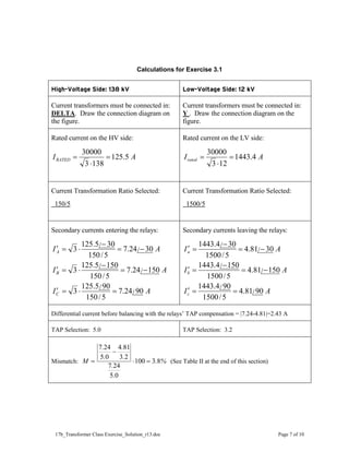
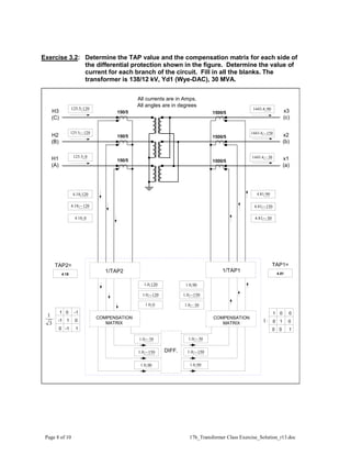
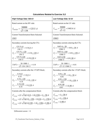
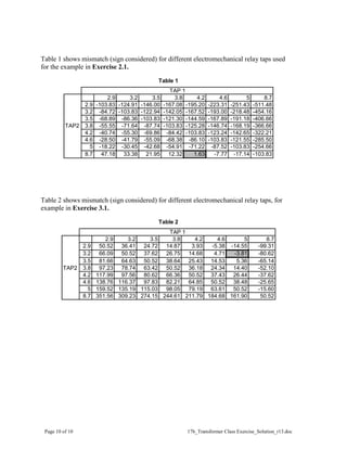
17b_Transformer Class Exercise_Solution_r13.doc Page 1 of 10
TRANSFORMER PROTECTION EXERCISE SOLUTION
Exercise 1.1: Determine a Typical Distribution Transformer Connection.
H3
H2
H1
X3
X2
X1
X0
C
B
A
c
b
a
n
Exercise 1.2: Determine a Typical Generator Step-up Transformer Connection.
H3
H2
H1
X3
X2
X1
H0
C
B
A
c
b
a
N
Page 2 of 10 17b_Transformer Class Exercise_Solution_r13.doc
Exercise 2.1: Determine the CT connections and transformation ratio for the
following step-down transformer. Assume the differential protection is
a traditional electromechanical relay. The transformer is 138/22 kV,
Dy1 (DAB-Wye), 60 MVA.
H1
(A)
H2
(B)
H3
(C)
x1
(a)
x2
(b)
x3
(c)
H1
H2
H3
X2
X3
X1
X0
Ib
Ia
Ic
IC
IB
IA
Relay Taps:
2.9 3.2 3.5 3.8 4.2 4.6 5.0 8.7
All currents are in Amps.
All angles are in degrees
300/5
300/5
300/5
1600/5
1600/5
1600/5
150
/
02
.
251
90
/
02
.
251 −
30
/
02
.
251
150
/
18
.
4
90
/
18
.
4 −
30
/
18
.
4
150
/
52
.
8
90
/
52
.
8 −
30
/
52
.
8
120
/
6
.
1574
120
/
6
.
1574 −
0
/
6
.
1574
High-Side CT
600/5 MR
600-500-450-400
300-250-200-150
100-50/5
Low-Side CT
2000/5 MR
2000-1600-1500-1200
1100-800-500-400-300/5
High-Side CT
600/5 MR
600-500-450-400
300-250-200-150
100-50/5
Low-Side CT
2000/5 MR
2000-1600-1500-1200
1100-800-500-400-300/5
IC
IB
IA
17b_Transformer Class Exercise_Solution_r13.doc Page 3 of 10
Calculations for Exercise 2.1
High-Voltage Side: 138 kV Low-Voltage Side: 22 kV
Current transformers must be connected in:
Y . Draw the connection diagram on the
figure.
Current transformers must be connected in:
DELTA. Draw the connection diagram on
the figure.
Rated current on the HV side:
A
IRATED 02
.
251
138
3
60000
=
⋅
=
Rated current on the LV side:
A
Irated 6
.
1574
22
3
60000
=
⋅
=
Current Transformation Ratio Selected:
300/5
Current Transformation Ratio Selected:
1600/5
Secondary currents entering the relays:
A
I
A
I
A
I
C
B
A
150
/
18
.
4
5
/
300
150
/
02
.
251
90
/
18
.
4
5
/
300
90
/
02
.
251
30
/
18
.
4
5
/
300
30
/
02
.
251
=
=
′
−
=
−
=
′
=
=
′
Secondary currents leaving the relays:
A
I
A
I
A
I
c
b
a
150
/
52
.
8
5
/
1600
150
/
6
.
1574
3
90
/
52
.
8
5
/
1600
90
/
6
.
1574
3
30
/
52
.
8
5
/
1600
30
/
6
.
1574
3
=
⋅
=
′
−
=
−
⋅
=
′
=
⋅
=
′
Differential current before balancing with the relay’s TAP compensation = |8.52-4.18| = 4.34 A
TAP Selection: 4.2 TAP Selection: 8.7
Mismatch: %
63
.
1
100
2
.
4
7
.
8
2
.
4
7
.
8
18
.
4
52
.
8
M =
⋅
−
= (See Table I at the end of this section).
Page 4 of 10 17b_Transformer Class Exercise_Solution_r13.doc
Exercise 2.2: Determine the TAP value and the compensation matrix for each side of
the differential protection shown in the figure. Determine the value of
current for each branch of the circuit. Fill in all the blanks. The
transformer is 138/22 kV, Dy1 (DAB-Wye), 60 MVA.
H1
(A)
H2
(B)
H3
(C)
x1
(a)
x2
(b)
x3
(c)
1/TAP1
COMPENSATION
MATRIX
COMPENSATION
MATRIX
DIFF.
TAP1= TAP2=
4.18 4.92
1 0 0
0 1 0
1
0
0
1 -1 0
0 1 -1
1
0
-1
All currents are in Amps.
All angles are in degrees
300/5
300/5
300/5
1600/5
1600/5
1600/5
1/TAP2
150
/
02
.
251
90
/
02
.
251 −
30
/
02
.
251
150
/
18
.
4
90
/
18
.
4 −
30
/
18
.
4
150
/
0
.
1
90
/
0
.
1 −
30
/
0
.
1
120
/
0
.
1
120
/
0
.
1 −
0
/
0
.
1
150
/
0
.
1
90
/
0
.
1 −
30
/
0
.
1
150
/
0
.
1
90
/
0
.
1 −
30
/
0
.
1
120
/
92
.
4
120
/
92
.
4 −
0
/
92
.
4
120
/
6
.
1574
120
/
6
.
1574 −
0
/
6
.
1574
⋅
3
1
⋅
1
17b_Transformer Class Exercise_Solution_r13.doc Page 5 of 10
Calculations Related to Exercise 2.2
High-Voltage Side: 138 kV Low-Voltage Side: 22 kV
Rated current on the HV side:
A
IRATED 02
.
251
138
3
60000
=
⋅
=
Rated current on the LV side:
A
Irated 6
.
1574
22
3
60000
=
⋅
=
Current Transformation Ratio Selected:
300/5
Current Transformation Ratio Selected:
1600/5
Secondary currents leaving the CT’s:
A
I
A
I
A
I
C
B
A
150
/
18
.
4
5
/
300
150
/
02
.
251
90
/
18
.
4
5
/
300
90
/
02
.
251
30
/
18
.
4
5
/
300
30
/
02
.
251
=
=
′
−
=
−
=
′
=
=
′
Secondary currents entering the CT’s:
A
I
A
I
A
I
c
b
a
120
/
92
.
4
5
/
1600
120
/
6
.
1574
120
/
92
.
4
5
/
1600
120
/
6
.
1574
0
/
92
.
4
5
/
1600
0
/
6
.
1574
=
=
′
−
=
−
=
′
=
=
′
18
.
4
5
/
300
138
3
1
1000
60
1 =
⋅
⋅
⋅
⋅
=
TAP 92
.
4
5
/
300
22
3
1
1000
60
2 =
⋅
⋅
⋅
⋅
=
TAP
Secondary currents after the 1/TAP1 block:
A
I
A
I
A
I
CT
BT
AT
150
/
0
.
1
18
.
4
150
/
18
.
4
90
/
0
.
1
18
.
4
90
/
18
.
4
30
/
0
.
1
18
.
4
30
/
18
.
4
=
=
′
−
=
−
=
′
=
=
′
Secondary currents after the 1/TAP2 block:
A
I
A
I
A
I
cT
bT
aT
120
/
0
.
1
92
.
4
120
/
92
.
4
120
/
0
.
1
92
.
4
120
/
92
.
4
0
/
0
.
1
92
.
4
0
/
92
.
4
=
=
′
−
=
−
=
′
=
=
′
Currents after the compensation block:
A
I
A
I
A
I
Ccomp
Bcomp
Acomp
150
/
1
90
/
1
30
/
1
=
′
−
=
′
=
′
Currents after the compensation block:
A
I
A
I
A
I
ccomp
bcomp
acomp
150
/
1
)
0
/
0
.
1
120
/
0
.
1
)(
3
/
1
(
90
/
1
)
120
/
0
.
1
120
/
0
.
1
)(
3
/
1
(
30
/
1
)
120
/
0
.
1
0
/
0
.
1
)(
3
/
1
(
=
−
=
′
−
=
−
−
=
′
=
−
−
=
′
Differential Current = 0
Page 6 of 10 17b_Transformer Class Exercise_Solution_r13.doc
Exercise 3.1: Determine the CT connections and transformation ratio for the
following step-up transformer. Assume the differential protection is a
traditional electromechanical relay. The transformer is 138/12 kV, Yd1
(Wye-DAC), 30 MVA.
H1
H2 X2
X3
X1
H0
x3
(c)
x2
(b)
x1
(a)
H3
(C)
H2
(B)
H1
(A)
IB
IC
IA Ia
Ib
Ic 1500/5
1500/5
1500/5
90
/
4
.
1443
150
/
4
.
1443 −
30
/
4
.
1443 −
90
/
81
.
4
150
/
81
.
4 −
30
/
81
.
4 −
90
/
24
.
7
150
/
24
.
7 −
30
/
24
.
7 −
0
/
5
.
125
120
/
5
.
125 −
120
/
5
.
125
H3
150/5
150/5
150/5
Relay Taps:
2.9 3.2 3.5 3.8 4.2 4.6 5.0 8.7
All currents are in Amps.
All angles are in degrees
High-Side CT
600/5 MR
600-500-450-400
300-250-200-150
100-50/5
Low-Side CT
2000/5 MR
2000-1600-1500-1200
1100-800-500-400-300/5
17b_Transformer Class Exercise_Solution_r13.doc Page 7 of 10
Calculations for Exercise 3.1
High-Voltage Side: 138 kV Low-Voltage Side: 12 kV
Current transformers must be connected in:
DELTA. Draw the connection diagram on
the figure.
Current transformers must be connected in:
Y . Draw the connection diagram on the
figure.
Rated current on the HV side:
A
IRATED 5
.
125
138
3
30000
=
⋅
=
Rated current on the LV side:
A
Irated 4
.
1443
12
3
30000
=
⋅
=
Current Transformation Ratio Selected:
150/5
Current Transformation Ratio Selected:
1500/5
Secondary currents entering the relays:
A
I
A
I
A
I
C
B
A
90
/
24
.
7
5
/
150
90
/
5
.
125
3
150
/
24
.
7
5
/
150
150
/
5
.
125
3
30
/
24
.
7
5
/
150
30
/
5
.
125
3
=
⋅
=
′
−
=
−
⋅
=
′
−
=
−
⋅
=
′
Secondary currents leaving the relays:
A
I
A
I
A
I
c
b
a
90
/
81
.
4
5
/
1500
90
/
4
.
1443
150
/
81
.
4
5
/
1500
150
/
4
.
1443
30
/
81
.
4
5
/
1500
30
/
4
.
1443
=
=
′
−
=
−
=
′
−
=
−
=
′
Differential current before balancing with the relays’ TAP compensation = |7.24-4.81|=2.43 A
TAP Selection: 5.0 TAP Selection: 3.2
Mismatch: %
.
.
.
.
.
.
.
M 8
3
100
0
5
24
7
2
3
81
4
0
5
24
7
=
⋅
−
= (See Table II at the end of this section)
Page 8 of 10 17b_Transformer Class Exercise_Solution_r13.doc
Exercise 3.2: Determine the TAP value and the compensation matrix for each side of
the differential protection shown in the figure. Determine the value of
current for each branch of the circuit. Fill in all the blanks. The
transformer is 138/12 kV, Yd1 (Wye-DAC), 30 MVA.
x1
(a)
x2
(b)
x3
(c)
H1
(A)
H2
(B)
H3
(C)
COMPENSATION
MATRIX
COMPENSATION
MATRIX
DIFF.
TAP1=
TAP2=
4.81
4.18
All currents are in Amps.
All angles are in degrees
1500/5
1500/5
1500/5
150/5
150/5
150/5
1/TAP2
90
/
4
.
1443
150
/
4
.
1443 −
30
/
4
.
1443 −
90
/
81
.
4
150
/
81
.
4 −
30
/
81
.
4 −
90
/
0
.
1
150
/
0
.
1 −
30
/
0
.
1 −
120
/
0
.
1
120
/
0
.
1 −
0
/
0
.
1
120
/
18
.
4
120
/
18
.
4 −
0
/
18
.
4
120
/
5
.
125
120
/
5
.
125 −
0
/
5
.
125
1/TAP1
1 0 0
0 1 0
1
0
0
⋅
1
1 0 -1
-1 1 0
1
-1
0
⋅
3
1
30
/
0
.
1 −
150
/
0
.
1 −
90
/
0
.
1
30
/
0
.
1 −
150
/
0
.
1 −
90
/
0
.
1
17b_Transformer Class Exercise_Solution_r13.doc Page 9 of 10
Calculations Related to Exercise 3.2
High-Voltage Side: 138 kV Low-Voltage Side: 12 kV
Rated current on the HV side:
A
IRATED 5
.
125
138
3
30000
=
⋅
=
Rated current on the LV side:
A
Irated 4
.
1443
12
3
30000
=
⋅
=
Current Transformation Ratio Selected:
150/5
Current Transformation Ratio Selected:
1500/5
Secondary currents leaving the CTs:
A
I
A
I
A
I
C
B
A
120
/
18
.
4
5
/
150
120
/
51
.
125
120
/
18
.
4
5
/
150
120
/
51
.
125
0
/
18
.
4
5
/
150
0
/
51
.
125
=
=
′
−
=
−
=
′
=
=
′
Secondary currents entering the CTs:
A
I
A
I
A
I
c
b
a
90
/
81
.
4
5
/
1500
90
/
4
.
1443
150
/
81
.
4
5
/
1500
150
/
4
.
1443
30
/
81
.
4
5
/
1500
30
/
4
.
1443
=
=
′
−
=
−
=
′
−
=
−
=
′
18
.
4
5
/
150
138
3
1
1000
30
2 =
⋅
⋅
⋅
⋅
=
TAP 81
.
4
5
/
1500
12
3
1
1000
30
1 =
⋅
⋅
⋅
⋅
=
TAP
Secondary currents after the 1/TAP2 block:
A
I
A
I
A
I
CT
BT
AT
120
/
0
.
1
18
.
4
120
/
18
.
4
120
/
0
.
1
18
.
4
120
/
18
.
4
0
/
0
.
1
18
.
4
0
/
18
.
4
=
=
′
−
=
−
=
′
=
=
′
Secondary currents after the 1/TAP1 block:
A
I
A
I
A
I
cT
bT
aT
90
/
0
.
1
81
.
4
90
/
81
.
4
150
/
0
.
1
81
.
4
150
/
81
.
4
30
/
0
.
1
81
.
4
30
/
81
.
4
=
=
′
−
=
−
=
′
−
=
−
=
′
Currents after the compensation block:
A
I
A
I
A
I
Ccomp
Bcomp
Acomp
90
/
1
)
120
/
0
.
1
120
/
0
.
1
)(
3
/
1
(
150
/
1
)
0
/
0
.
1
120
/
0
.
1
)(
3
/
1
(
30
/
1
)
120
/
0
.
1
0
/
0
.
1
)(
3
/
1
(
=
−
−
=
′
−
=
−
−
=
′
−
=
−
=
′
Currents after the compensation block:
A
I
A
I
A
I
ccomp
bcomp
acomp
90
/
1
150
/
1
30
/
1
=
′
−
=
−
=
′
Differential current = 0
Page 10 of 10 17b_Transformer Class Exercise_Solution_r13.doc
Table 1 shows mismatch (sign considered) for different electromechanical relay taps used
for the example in Exercise 2.1.
Table 1
Table 2 shows mismatch (sign considered) for different electromechanical relay taps, for
example in Exercise 3.1.
Table 2
2.9 3.2 3.5 3.8 4.2 4.6 5 8.7
2.9 -103.83 -124.91 -146.00 -167.08 -195.20 -223.31 -251.43 -511.48
3.2 -84.72 -103.83 -122.94 -142.05 -167.52 -193.00 -218.48 -454.16
3.5 -68.89 -86.36 -103.83 -121.30 -144.59 -167.89 -191.18 -406.66
TAP2 3.8 -55.55 -71.64 -87.74 -103.83 -125.28 -146.74 -168.19 -366.66
4.2 -40.74 -55.30 -69.86 -84.42 -103.83 -123.24 -142.65 -322.21
4.6 -28.50 -41.79 -55.09 -68.38 -86.10 -103.83 -121.55 -285.50
5 -18.22 -30.45 -42.68 -54.91 -71.22 -87.52 -103.83 -254.66
8.7 47.18 33.38 21.95 12.32 1.63 -7.77 -17.14 -103.83
TAP 1
2.9 3.2 3.5 3.8 4.2 4.6 5 8.7
2.9 50.52 36.41 24.72 14.87 3.93 -5.38 -14.55 -99.31
3.2 66.09 50.52 37.62 26.75 14.68 4.71 -3.81 -80.62
3.5 81.66 64.63 50.52 38.64 25.43 14.53 5.36 -65.14
TAP2 3.8 97.23 78.74 63.42 50.52 36.18 24.34 14.40 -52.10
4.2 117.99 97.56 80.62 66.36 50.52 37.43 26.44 -37.62
4.6 138.76 116.37 97.83 82.21 64.85 50.52 38.48 -25.65
5 159.52 135.19 115.03 98.05 79.19 63.61 50.52 -15.60
8.7 351.56 309.23 274.15 244.61 211.79 184.68 161.90 50.52
TAP 1

17b transformer class exercise solution_r13

  • 1.
    17b_Transformer Class Exercise_Solution_r13.docPage 1 of 10 TRANSFORMER PROTECTION EXERCISE SOLUTION Exercise 1.1: Determine a Typical Distribution Transformer Connection. H3 H2 H1 X3 X2 X1 X0 C B A c b a n Exercise 1.2: Determine a Typical Generator Step-up Transformer Connection. H3 H2 H1 X3 X2 X1 H0 C B A c b a N
  • 2.
    Page 2 of10 17b_Transformer Class Exercise_Solution_r13.doc Exercise 2.1: Determine the CT connections and transformation ratio for the following step-down transformer. Assume the differential protection is a traditional electromechanical relay. The transformer is 138/22 kV, Dy1 (DAB-Wye), 60 MVA. H1 (A) H2 (B) H3 (C) x1 (a) x2 (b) x3 (c) H1 H2 H3 X2 X3 X1 X0 Ib Ia Ic IC IB IA Relay Taps: 2.9 3.2 3.5 3.8 4.2 4.6 5.0 8.7 All currents are in Amps. All angles are in degrees 300/5 300/5 300/5 1600/5 1600/5 1600/5 150 / 02 . 251 90 / 02 . 251 − 30 / 02 . 251 150 / 18 . 4 90 / 18 . 4 − 30 / 18 . 4 150 / 52 . 8 90 / 52 . 8 − 30 / 52 . 8 120 / 6 . 1574 120 / 6 . 1574 − 0 / 6 . 1574 High-Side CT 600/5 MR 600-500-450-400 300-250-200-150 100-50/5 Low-Side CT 2000/5 MR 2000-1600-1500-1200 1100-800-500-400-300/5 High-Side CT 600/5 MR 600-500-450-400 300-250-200-150 100-50/5 Low-Side CT 2000/5 MR 2000-1600-1500-1200 1100-800-500-400-300/5 IC IB IA
  • 3.
    17b_Transformer Class Exercise_Solution_r13.docPage 3 of 10 Calculations for Exercise 2.1 High-Voltage Side: 138 kV Low-Voltage Side: 22 kV Current transformers must be connected in: Y . Draw the connection diagram on the figure. Current transformers must be connected in: DELTA. Draw the connection diagram on the figure. Rated current on the HV side: A IRATED 02 . 251 138 3 60000 = ⋅ = Rated current on the LV side: A Irated 6 . 1574 22 3 60000 = ⋅ = Current Transformation Ratio Selected: 300/5 Current Transformation Ratio Selected: 1600/5 Secondary currents entering the relays: A I A I A I C B A 150 / 18 . 4 5 / 300 150 / 02 . 251 90 / 18 . 4 5 / 300 90 / 02 . 251 30 / 18 . 4 5 / 300 30 / 02 . 251 = = ′ − = − = ′ = = ′ Secondary currents leaving the relays: A I A I A I c b a 150 / 52 . 8 5 / 1600 150 / 6 . 1574 3 90 / 52 . 8 5 / 1600 90 / 6 . 1574 3 30 / 52 . 8 5 / 1600 30 / 6 . 1574 3 = ⋅ = ′ − = − ⋅ = ′ = ⋅ = ′ Differential current before balancing with the relay’s TAP compensation = |8.52-4.18| = 4.34 A TAP Selection: 4.2 TAP Selection: 8.7 Mismatch: % 63 . 1 100 2 . 4 7 . 8 2 . 4 7 . 8 18 . 4 52 . 8 M = ⋅ − = (See Table I at the end of this section).
  • 4.
    Page 4 of10 17b_Transformer Class Exercise_Solution_r13.doc Exercise 2.2: Determine the TAP value and the compensation matrix for each side of the differential protection shown in the figure. Determine the value of current for each branch of the circuit. Fill in all the blanks. The transformer is 138/22 kV, Dy1 (DAB-Wye), 60 MVA. H1 (A) H2 (B) H3 (C) x1 (a) x2 (b) x3 (c) 1/TAP1 COMPENSATION MATRIX COMPENSATION MATRIX DIFF. TAP1= TAP2= 4.18 4.92 1 0 0 0 1 0 1 0 0 1 -1 0 0 1 -1 1 0 -1 All currents are in Amps. All angles are in degrees 300/5 300/5 300/5 1600/5 1600/5 1600/5 1/TAP2 150 / 02 . 251 90 / 02 . 251 − 30 / 02 . 251 150 / 18 . 4 90 / 18 . 4 − 30 / 18 . 4 150 / 0 . 1 90 / 0 . 1 − 30 / 0 . 1 120 / 0 . 1 120 / 0 . 1 − 0 / 0 . 1 150 / 0 . 1 90 / 0 . 1 − 30 / 0 . 1 150 / 0 . 1 90 / 0 . 1 − 30 / 0 . 1 120 / 92 . 4 120 / 92 . 4 − 0 / 92 . 4 120 / 6 . 1574 120 / 6 . 1574 − 0 / 6 . 1574 ⋅ 3 1 ⋅ 1
  • 5.
    17b_Transformer Class Exercise_Solution_r13.docPage 5 of 10 Calculations Related to Exercise 2.2 High-Voltage Side: 138 kV Low-Voltage Side: 22 kV Rated current on the HV side: A IRATED 02 . 251 138 3 60000 = ⋅ = Rated current on the LV side: A Irated 6 . 1574 22 3 60000 = ⋅ = Current Transformation Ratio Selected: 300/5 Current Transformation Ratio Selected: 1600/5 Secondary currents leaving the CT’s: A I A I A I C B A 150 / 18 . 4 5 / 300 150 / 02 . 251 90 / 18 . 4 5 / 300 90 / 02 . 251 30 / 18 . 4 5 / 300 30 / 02 . 251 = = ′ − = − = ′ = = ′ Secondary currents entering the CT’s: A I A I A I c b a 120 / 92 . 4 5 / 1600 120 / 6 . 1574 120 / 92 . 4 5 / 1600 120 / 6 . 1574 0 / 92 . 4 5 / 1600 0 / 6 . 1574 = = ′ − = − = ′ = = ′ 18 . 4 5 / 300 138 3 1 1000 60 1 = ⋅ ⋅ ⋅ ⋅ = TAP 92 . 4 5 / 300 22 3 1 1000 60 2 = ⋅ ⋅ ⋅ ⋅ = TAP Secondary currents after the 1/TAP1 block: A I A I A I CT BT AT 150 / 0 . 1 18 . 4 150 / 18 . 4 90 / 0 . 1 18 . 4 90 / 18 . 4 30 / 0 . 1 18 . 4 30 / 18 . 4 = = ′ − = − = ′ = = ′ Secondary currents after the 1/TAP2 block: A I A I A I cT bT aT 120 / 0 . 1 92 . 4 120 / 92 . 4 120 / 0 . 1 92 . 4 120 / 92 . 4 0 / 0 . 1 92 . 4 0 / 92 . 4 = = ′ − = − = ′ = = ′ Currents after the compensation block: A I A I A I Ccomp Bcomp Acomp 150 / 1 90 / 1 30 / 1 = ′ − = ′ = ′ Currents after the compensation block: A I A I A I ccomp bcomp acomp 150 / 1 ) 0 / 0 . 1 120 / 0 . 1 )( 3 / 1 ( 90 / 1 ) 120 / 0 . 1 120 / 0 . 1 )( 3 / 1 ( 30 / 1 ) 120 / 0 . 1 0 / 0 . 1 )( 3 / 1 ( = − = ′ − = − − = ′ = − − = ′ Differential Current = 0
  • 6.
    Page 6 of10 17b_Transformer Class Exercise_Solution_r13.doc Exercise 3.1: Determine the CT connections and transformation ratio for the following step-up transformer. Assume the differential protection is a traditional electromechanical relay. The transformer is 138/12 kV, Yd1 (Wye-DAC), 30 MVA. H1 H2 X2 X3 X1 H0 x3 (c) x2 (b) x1 (a) H3 (C) H2 (B) H1 (A) IB IC IA Ia Ib Ic 1500/5 1500/5 1500/5 90 / 4 . 1443 150 / 4 . 1443 − 30 / 4 . 1443 − 90 / 81 . 4 150 / 81 . 4 − 30 / 81 . 4 − 90 / 24 . 7 150 / 24 . 7 − 30 / 24 . 7 − 0 / 5 . 125 120 / 5 . 125 − 120 / 5 . 125 H3 150/5 150/5 150/5 Relay Taps: 2.9 3.2 3.5 3.8 4.2 4.6 5.0 8.7 All currents are in Amps. All angles are in degrees High-Side CT 600/5 MR 600-500-450-400 300-250-200-150 100-50/5 Low-Side CT 2000/5 MR 2000-1600-1500-1200 1100-800-500-400-300/5
  • 7.
    17b_Transformer Class Exercise_Solution_r13.docPage 7 of 10 Calculations for Exercise 3.1 High-Voltage Side: 138 kV Low-Voltage Side: 12 kV Current transformers must be connected in: DELTA. Draw the connection diagram on the figure. Current transformers must be connected in: Y . Draw the connection diagram on the figure. Rated current on the HV side: A IRATED 5 . 125 138 3 30000 = ⋅ = Rated current on the LV side: A Irated 4 . 1443 12 3 30000 = ⋅ = Current Transformation Ratio Selected: 150/5 Current Transformation Ratio Selected: 1500/5 Secondary currents entering the relays: A I A I A I C B A 90 / 24 . 7 5 / 150 90 / 5 . 125 3 150 / 24 . 7 5 / 150 150 / 5 . 125 3 30 / 24 . 7 5 / 150 30 / 5 . 125 3 = ⋅ = ′ − = − ⋅ = ′ − = − ⋅ = ′ Secondary currents leaving the relays: A I A I A I c b a 90 / 81 . 4 5 / 1500 90 / 4 . 1443 150 / 81 . 4 5 / 1500 150 / 4 . 1443 30 / 81 . 4 5 / 1500 30 / 4 . 1443 = = ′ − = − = ′ − = − = ′ Differential current before balancing with the relays’ TAP compensation = |7.24-4.81|=2.43 A TAP Selection: 5.0 TAP Selection: 3.2 Mismatch: % . . . . . . . M 8 3 100 0 5 24 7 2 3 81 4 0 5 24 7 = ⋅ − = (See Table II at the end of this section)
  • 8.
    Page 8 of10 17b_Transformer Class Exercise_Solution_r13.doc Exercise 3.2: Determine the TAP value and the compensation matrix for each side of the differential protection shown in the figure. Determine the value of current for each branch of the circuit. Fill in all the blanks. The transformer is 138/12 kV, Yd1 (Wye-DAC), 30 MVA. x1 (a) x2 (b) x3 (c) H1 (A) H2 (B) H3 (C) COMPENSATION MATRIX COMPENSATION MATRIX DIFF. TAP1= TAP2= 4.81 4.18 All currents are in Amps. All angles are in degrees 1500/5 1500/5 1500/5 150/5 150/5 150/5 1/TAP2 90 / 4 . 1443 150 / 4 . 1443 − 30 / 4 . 1443 − 90 / 81 . 4 150 / 81 . 4 − 30 / 81 . 4 − 90 / 0 . 1 150 / 0 . 1 − 30 / 0 . 1 − 120 / 0 . 1 120 / 0 . 1 − 0 / 0 . 1 120 / 18 . 4 120 / 18 . 4 − 0 / 18 . 4 120 / 5 . 125 120 / 5 . 125 − 0 / 5 . 125 1/TAP1 1 0 0 0 1 0 1 0 0 ⋅ 1 1 0 -1 -1 1 0 1 -1 0 ⋅ 3 1 30 / 0 . 1 − 150 / 0 . 1 − 90 / 0 . 1 30 / 0 . 1 − 150 / 0 . 1 − 90 / 0 . 1
  • 9.
    17b_Transformer Class Exercise_Solution_r13.docPage 9 of 10 Calculations Related to Exercise 3.2 High-Voltage Side: 138 kV Low-Voltage Side: 12 kV Rated current on the HV side: A IRATED 5 . 125 138 3 30000 = ⋅ = Rated current on the LV side: A Irated 4 . 1443 12 3 30000 = ⋅ = Current Transformation Ratio Selected: 150/5 Current Transformation Ratio Selected: 1500/5 Secondary currents leaving the CTs: A I A I A I C B A 120 / 18 . 4 5 / 150 120 / 51 . 125 120 / 18 . 4 5 / 150 120 / 51 . 125 0 / 18 . 4 5 / 150 0 / 51 . 125 = = ′ − = − = ′ = = ′ Secondary currents entering the CTs: A I A I A I c b a 90 / 81 . 4 5 / 1500 90 / 4 . 1443 150 / 81 . 4 5 / 1500 150 / 4 . 1443 30 / 81 . 4 5 / 1500 30 / 4 . 1443 = = ′ − = − = ′ − = − = ′ 18 . 4 5 / 150 138 3 1 1000 30 2 = ⋅ ⋅ ⋅ ⋅ = TAP 81 . 4 5 / 1500 12 3 1 1000 30 1 = ⋅ ⋅ ⋅ ⋅ = TAP Secondary currents after the 1/TAP2 block: A I A I A I CT BT AT 120 / 0 . 1 18 . 4 120 / 18 . 4 120 / 0 . 1 18 . 4 120 / 18 . 4 0 / 0 . 1 18 . 4 0 / 18 . 4 = = ′ − = − = ′ = = ′ Secondary currents after the 1/TAP1 block: A I A I A I cT bT aT 90 / 0 . 1 81 . 4 90 / 81 . 4 150 / 0 . 1 81 . 4 150 / 81 . 4 30 / 0 . 1 81 . 4 30 / 81 . 4 = = ′ − = − = ′ − = − = ′ Currents after the compensation block: A I A I A I Ccomp Bcomp Acomp 90 / 1 ) 120 / 0 . 1 120 / 0 . 1 )( 3 / 1 ( 150 / 1 ) 0 / 0 . 1 120 / 0 . 1 )( 3 / 1 ( 30 / 1 ) 120 / 0 . 1 0 / 0 . 1 )( 3 / 1 ( = − − = ′ − = − − = ′ − = − = ′ Currents after the compensation block: A I A I A I ccomp bcomp acomp 90 / 1 150 / 1 30 / 1 = ′ − = − = ′ Differential current = 0
  • 10.
    Page 10 of10 17b_Transformer Class Exercise_Solution_r13.doc Table 1 shows mismatch (sign considered) for different electromechanical relay taps used for the example in Exercise 2.1. Table 1 Table 2 shows mismatch (sign considered) for different electromechanical relay taps, for example in Exercise 3.1. Table 2 2.9 3.2 3.5 3.8 4.2 4.6 5 8.7 2.9 -103.83 -124.91 -146.00 -167.08 -195.20 -223.31 -251.43 -511.48 3.2 -84.72 -103.83 -122.94 -142.05 -167.52 -193.00 -218.48 -454.16 3.5 -68.89 -86.36 -103.83 -121.30 -144.59 -167.89 -191.18 -406.66 TAP2 3.8 -55.55 -71.64 -87.74 -103.83 -125.28 -146.74 -168.19 -366.66 4.2 -40.74 -55.30 -69.86 -84.42 -103.83 -123.24 -142.65 -322.21 4.6 -28.50 -41.79 -55.09 -68.38 -86.10 -103.83 -121.55 -285.50 5 -18.22 -30.45 -42.68 -54.91 -71.22 -87.52 -103.83 -254.66 8.7 47.18 33.38 21.95 12.32 1.63 -7.77 -17.14 -103.83 TAP 1 2.9 3.2 3.5 3.8 4.2 4.6 5 8.7 2.9 50.52 36.41 24.72 14.87 3.93 -5.38 -14.55 -99.31 3.2 66.09 50.52 37.62 26.75 14.68 4.71 -3.81 -80.62 3.5 81.66 64.63 50.52 38.64 25.43 14.53 5.36 -65.14 TAP2 3.8 97.23 78.74 63.42 50.52 36.18 24.34 14.40 -52.10 4.2 117.99 97.56 80.62 66.36 50.52 37.43 26.44 -37.62 4.6 138.76 116.37 97.83 82.21 64.85 50.52 38.48 -25.65 5 159.52 135.19 115.03 98.05 79.19 63.61 50.52 -15.60 8.7 351.56 309.23 274.15 244.61 211.79 184.68 161.90 50.52 TAP 1