Download to read offline
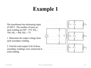
![Power, Currents, Voltage, Flux
1/12/2023 Prof. Z. Jan Bochynski 16
]
[
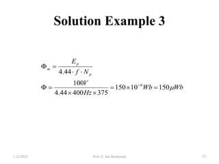
44
.
4
4
11
.
1 V
N
f
N
f
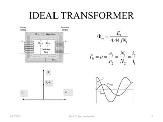
E m
m
rms
](https://image.slidesharecdn.com/transformersforee-uy-2613-230112162128-5077698d/85/TRANSFORMERS-FOR-EE-UY-2613-pptx-16-320.jpg)
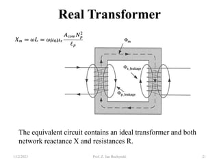
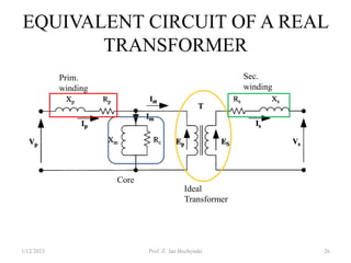
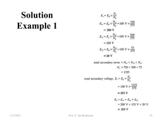
![Real Transformer Equivalent Circuit
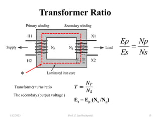
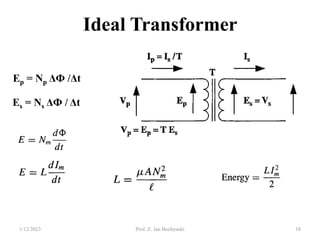
Ep =4.44 Фm f Np [V]
Es = 4.44 Фm f Ns [V]
Ф (Wb), f (Hz)
Ep = Vp + ΔVp = Vp + (IoRp + Io Xp )
Vp = Ep - ΔVp = Ep + (IoRp + Io Xp )
1/12/2023 Prof. Z. Jan Bochynski 27](https://image.slidesharecdn.com/transformersforee-uy-2613-230112162128-5077698d/85/TRANSFORMERS-FOR-EE-UY-2613-pptx-27-320.jpg)
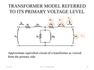
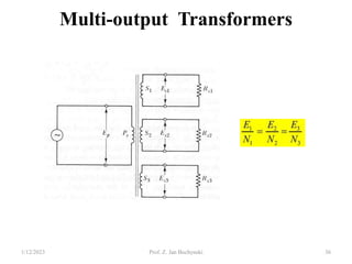
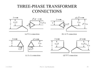
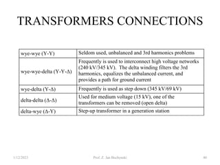
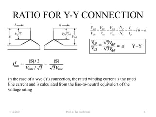
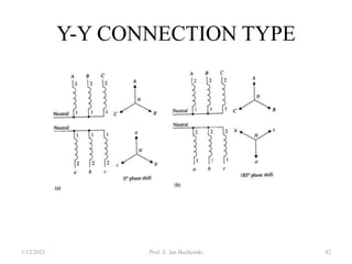
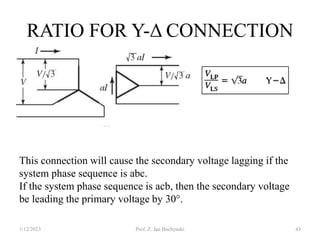
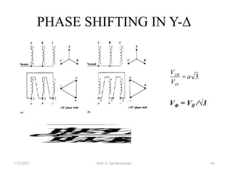
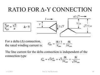
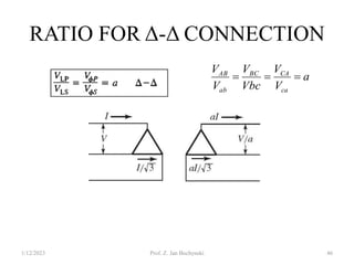


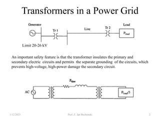
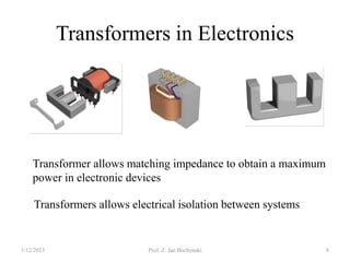
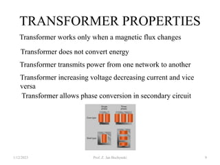
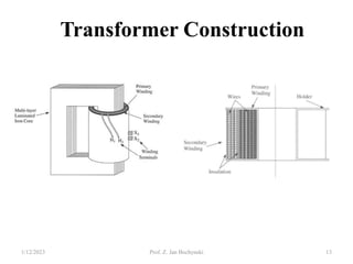
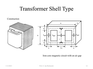
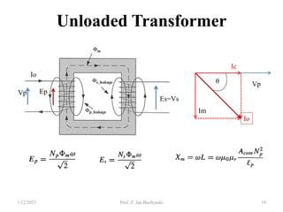
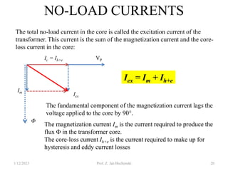
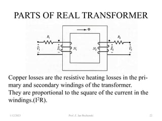
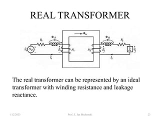
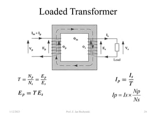
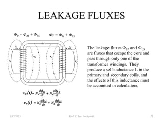
- Transformers allow the transfer of power between circuits at different voltage levels through electromagnetic induction. They work by changing the voltage and current in opposite proportions while keeping power constant. - An ideal transformer has no losses, but a real transformer is modeled with winding resistances and leakage reactances to account for energy losses. - Transformers can be connected in various configurations depending on the application, including wye-wye, wye-delta, delta-delta, etc. Proper transformer selection and connection is important for voltage regulation and power transmission efficiency.


![Chapter_3-Transformers[1]-1.pdf](https://cdn.slidesharecdn.com/ss_thumbnails/chapter3-transformers1-1-230622173423-be6efc48-thumbnail.jpg?width=640&height=640&fit=bounds)


