Flow nets provide a graphical representation of solutions to the Laplace equation for two-dimensional seepage. A flow net consists of two orthogonal sets of curves: equipotential lines connecting points of equal total head, and flow lines indicating the direction of seepage. The space between adjacent flow lines is called a flow channel. If the fields of a flow net are square (have equal dimensions) it is called a square flow net, where the rate of flow is equal between each channel. The number of flow channels and equipotential line drops determine the total flow rate according to Darcy's law.
Geotechnical Engineering-I [Lec #27A: Flow Calculation From Flow Nets]Muhammad Irfan
Class notes of Geotechnical Engineering course I used to teach at UET Lahore. Feel free to download the slide show.
Anyone looking to modify these files and use them for their own teaching purposes can contact me directly to get hold of editable version.
Experimental conceptualisation of the Flow Net system construction inside the...Dr.Costas Sachpazis
ABSTRACT
By means of a drainage and seepage tank, an experimental flow net system inside the body of a homogeneous earth embankment dam model, formed from Leighton Buzzard Silica sand, was developed and studied in this experimental research paper.
Water flow through dams is one of the basic problems for geotechnical engineers. Seepage analysis in an important factor to be considered in the proper design of many civil engineering structures. Seepage can occur in both through the structure itself as the case of earth dams and under foundations of an engineering structure. Successful seepage analysis is achieved on the proper and accurate construction of a flow net.
Amongst the various existing methods of seepage analysis, the “Finite Element Method” and the method of “Experimental Flow Nets” are the most widely used ones.
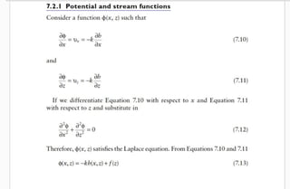
Construction of a flow net is mainly used for solving water flow problems through porous media where the geometry makes sometimes analytical solutions impractical. This method is usually used in soil mechanics, geotechnical or civil engineering as an initial check for problems of water flow under hydraulic structures like embankments or dams. As such, a grid obtained by drawing a series of equipotential lines and stream or flow lines is called a flow net. In this procedure the Laplace equation principles must be satisfied.
Hence, the construction of a flow net is an important tool in analysing two-dimensional irrotational flow problems and provides an approximate solution to the flow problem by following simple rules, as initially set out by Forchheimer, 1900, and later refined by Casagrande,1937. It can also be very useful tool even for problems with complex geometries, as proven in this experimental research paper.
The objectives of this experimental research paper are:
• To determine the position and shape of the flow line representing the uppermost free water surface inside the body of a dam by using a drainage and seepage tank,
• To conceptualise the flow lines system and to demonstrate that each flow line starts perpendicular to the upstream slope of the dam and that that slope is a boundary equipotential line,
• To construct an experimental flow net and subsequently to verify and analyse it by the FEA method,
• To calculate the rate of seepage through the dam body, and
• To summarise the calculations and experimental findings in a concise and readable format.
In order to achieve these objectives, an experimental flow net system inside the body of a homogeneous earth embankment dam model was formulated by using a drainage and seepage tank.
From the constructed flow net in the present experimental research paper, an attempt has been made to analyze, determine and present the following parameters:
The pressure drop from one side of the embankment to the other,
The seepage flow rate in each flow “channel”,
The total seepage flow rate, and
The pore pressure ratio, ru, for the embankment.
Geotechnical Engineering-I [Lec #27A: Flow Calculation From Flow Nets]Muhammad Irfan
Class notes of Geotechnical Engineering course I used to teach at UET Lahore. Feel free to download the slide show.
Anyone looking to modify these files and use them for their own teaching purposes can contact me directly to get hold of editable version.
Experimental conceptualisation of the Flow Net system construction inside the...Dr.Costas Sachpazis
ABSTRACT
By means of a drainage and seepage tank, an experimental flow net system inside the body of a homogeneous earth embankment dam model, formed from Leighton Buzzard Silica sand, was developed and studied in this experimental research paper.
Water flow through dams is one of the basic problems for geotechnical engineers. Seepage analysis in an important factor to be considered in the proper design of many civil engineering structures. Seepage can occur in both through the structure itself as the case of earth dams and under foundations of an engineering structure. Successful seepage analysis is achieved on the proper and accurate construction of a flow net.
Amongst the various existing methods of seepage analysis, the “Finite Element Method” and the method of “Experimental Flow Nets” are the most widely used ones.
Construction of a flow net is mainly used for solving water flow problems through porous media where the geometry makes sometimes analytical solutions impractical. This method is usually used in soil mechanics, geotechnical or civil engineering as an initial check for problems of water flow under hydraulic structures like embankments or dams. As such, a grid obtained by drawing a series of equipotential lines and stream or flow lines is called a flow net. In this procedure the Laplace equation principles must be satisfied.
Hence, the construction of a flow net is an important tool in analysing two-dimensional irrotational flow problems and provides an approximate solution to the flow problem by following simple rules, as initially set out by Forchheimer, 1900, and later refined by Casagrande,1937. It can also be very useful tool even for problems with complex geometries, as proven in this experimental research paper.
The objectives of this experimental research paper are:
• To determine the position and shape of the flow line representing the uppermost free water surface inside the body of a dam by using a drainage and seepage tank,
• To conceptualise the flow lines system and to demonstrate that each flow line starts perpendicular to the upstream slope of the dam and that that slope is a boundary equipotential line,
• To construct an experimental flow net and subsequently to verify and analyse it by the FEA method,
• To calculate the rate of seepage through the dam body, and
• To summarise the calculations and experimental findings in a concise and readable format.
In order to achieve these objectives, an experimental flow net system inside the body of a homogeneous earth embankment dam model was formulated by using a drainage and seepage tank.
From the constructed flow net in the present experimental research paper, an attempt has been made to analyze, determine and present the following parameters:
The pressure drop from one side of the embankment to the other,
The seepage flow rate in each flow “channel”,
The total seepage flow rate, and
The pore pressure ratio, ru, for the embankment.
Large eddy simulation of the flow over a circular cylinder at high reynolds n...Jesús Martínez
The issue of numerical study of turbulent flow over a circular cylinder for different Reynolds numbers has been studied over almost 20 years. During those two decades, there have been successes and failures in the numerical models. This paper presents the implementation of the method of large eddy simulation (LES) to solve the problem of the external flow over a cylinder under a subcritical Reynolds number (Re = 1.4E +5). The purpose is to evaluate the performance of a computational method and complement experimental and numerical data presented in the literature, this as part of a research work which attempts to explain a method of passive drag reduction.
Water scarcity is the lack of fresh water resources to meet the standard water demand. There are two type of water scarcity. One is physical. The other is economic water scarcity.
Hierarchical Digital Twin of a Naval Power SystemKerry Sado
A hierarchical digital twin of a Naval DC power system has been developed and experimentally verified. Similar to other state-of-the-art digital twins, this technology creates a digital replica of the physical system executed in real-time or faster, which can modify hardware controls. However, its advantage stems from distributing computational efforts by utilizing a hierarchical structure composed of lower-level digital twin blocks and a higher-level system digital twin. Each digital twin block is associated with a physical subsystem of the hardware and communicates with a singular system digital twin, which creates a system-level response. By extracting information from each level of the hierarchy, power system controls of the hardware were reconfigured autonomously. This hierarchical digital twin development offers several advantages over other digital twins, particularly in the field of naval power systems. The hierarchical structure allows for greater computational efficiency and scalability while the ability to autonomously reconfigure hardware controls offers increased flexibility and responsiveness. The hierarchical decomposition and models utilized were well aligned with the physical twin, as indicated by the maximum deviations between the developed digital twin hierarchy and the hardware.
Cosmetic shop management system project report.pdfKamal Acharya
Buying new cosmetic products is difficult. It can even be scary for those who have sensitive skin and are prone to skin trouble. The information needed to alleviate this problem is on the back of each product, but it's thought to interpret those ingredient lists unless you have a background in chemistry.
Instead of buying and hoping for the best, we can use data science to help us predict which products may be good fits for us. It includes various function programs to do the above mentioned tasks.
Data file handling has been effectively used in the program.
The automated cosmetic shop management system should deal with the automation of general workflow and administration process of the shop. The main processes of the system focus on customer's request where the system is able to search the most appropriate products and deliver it to the customers. It should help the employees to quickly identify the list of cosmetic product that have reached the minimum quantity and also keep a track of expired date for each cosmetic product. It should help the employees to find the rack number in which the product is placed.It is also Faster and more efficient way.
About
Indigenized remote control interface card suitable for MAFI system CCR equipment. Compatible for IDM8000 CCR. Backplane mounted serial and TCP/Ethernet communication module for CCR remote access. IDM 8000 CCR remote control on serial and TCP protocol.
• Remote control: Parallel or serial interface.
• Compatible with MAFI CCR system.
• Compatible with IDM8000 CCR.
• Compatible with Backplane mount serial communication.
• Compatible with commercial and Defence aviation CCR system.
• Remote control system for accessing CCR and allied system over serial or TCP.
• Indigenized local Support/presence in India.
• Easy in configuration using DIP switches.
Technical Specifications
Indigenized remote control interface card suitable for MAFI system CCR equipment. Compatible for IDM8000 CCR. Backplane mounted serial and TCP/Ethernet communication module for CCR remote access. IDM 8000 CCR remote control on serial and TCP protocol.
Key Features
Indigenized remote control interface card suitable for MAFI system CCR equipment. Compatible for IDM8000 CCR. Backplane mounted serial and TCP/Ethernet communication module for CCR remote access. IDM 8000 CCR remote control on serial and TCP protocol.
• Remote control: Parallel or serial interface
• Compatible with MAFI CCR system
• Copatiable with IDM8000 CCR
• Compatible with Backplane mount serial communication.
• Compatible with commercial and Defence aviation CCR system.
• Remote control system for accessing CCR and allied system over serial or TCP.
• Indigenized local Support/presence in India.
Application
• Remote control: Parallel or serial interface.
• Compatible with MAFI CCR system.
• Compatible with IDM8000 CCR.
• Compatible with Backplane mount serial communication.
• Compatible with commercial and Defence aviation CCR system.
• Remote control system for accessing CCR and allied system over serial or TCP.
• Indigenized local Support/presence in India.
• Easy in configuration using DIP switches.
Overview of the fundamental roles in Hydropower generation and the components involved in wider Electrical Engineering.
This paper presents the design and construction of hydroelectric dams from the hydrologist’s survey of the valley before construction, all aspects and involved disciplines, fluid dynamics, structural engineering, generation and mains frequency regulation to the very transmission of power through the network in the United Kingdom.
Author: Robbie Edward Sayers
Collaborators and co editors: Charlie Sims and Connor Healey.
(C) 2024 Robbie E. Sayers
Welcome to WIPAC Monthly the magazine brought to you by the LinkedIn Group Water Industry Process Automation & Control.
In this month's edition, along with this month's industry news to celebrate the 13 years since the group was created we have articles including
A case study of the used of Advanced Process Control at the Wastewater Treatment works at Lleida in Spain
A look back on an article on smart wastewater networks in order to see how the industry has measured up in the interim around the adoption of Digital Transformation in the Water Industry.
6. Flow Nets
Graphical form of solutions to Laplace equation for two-dimensional
seepage can be presented as flow nets. Two orthogonal sets of curves
form a flow net:
Equipotential lines connecting points of equal total head h
Flow lines indicating the direction of seepage down a hydraulic
gradient
Two flow lines can never meet and similarly, two equipotential lines can
never meet. The space between two adjacent flow lines is known as a flow
channel, and the figure formed on the flownet between any two adjacent
flow lines and two adjacent equipotential lines is referred to as a field
Referring the following field
The curvilinear average distance between the two adjacent equipotential lines =L
and head drop = ∆h, therefore gradient of flow i. = ∆h/L. In the above figure, b is
the average curvilinear distance between two successive flow lines, then rate of
inflow ∆q = k . i. b.1, here the width normal to the bed is considered unity. So, ∆q
= k . ∆h . b/L.
Characteristics of Square Flow Net. If any flow net having its fields square i.e. b =
L then it is called a square flow net. In case of square flownet ∆q = k. ∆h.
7. Now from the equation of continuity of steady flow, the inflow any field = outflow
from that field which implies that for any particular flow channel bounded by two
adjacent flow lines flow is uniform and hence for any successive fields, head drops
at any two equipotential lines are equal.
Thus if in any flownet, there are n number of potential lines, than number of drop
Nd = n-1 and ∆h = h/Nd when h is the total head drop between upstream and
downstream and so, ∆q = k. h /Nd.
Let’s assume there are Nf number of flow channels, and since for any two
successive equipotential lines head drop ∆h = h/Nd is constant, we can draw
inference that flow through each flow channels ∆q = k. h/ Nd are also equal, so
Total flow q = k. h. Nf/Nd.
Note: In any flownet, Nd is always an integer, though Nf does not. As because at
the boundary of the flownet, it is very rare to have all flow fields are square and
hence looking from the graph we have to approximate it to some decimal values.
Characteristics of Flownet: During drawing the flownet on graph-paper we have
to keep following points namely,
1. No two equaipotential lines should intersect or even touch at any point.
2. No two flow lines should intersect or even touch at any point.
3. The equipotential lines and flow lines should intersect at right angle to
each other.
4. Both the lines should be smooth and free of any sharp bend.