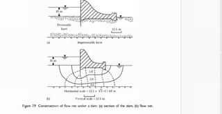
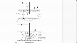
This document discusses constructing flow nets to analyze seepage in anisotropic soils where permeability varies in horizontal and vertical directions. It provides the procedure for plotting flow nets in anisotropic soils by transforming the horizontal scale based on the ratio of horizontal to vertical permeability. The steps include: 1) adopting vertical and transformed horizontal scales, 2) plotting the cross-section using these scales, 3) drawing the flow net in the transformed plane, and 4) replotting the flow net in the natural scale. An example problem applies these steps to construct the flow net for a sheet pile structure with a given permeability ratio and calculates the equivalent permeability.
![l
i
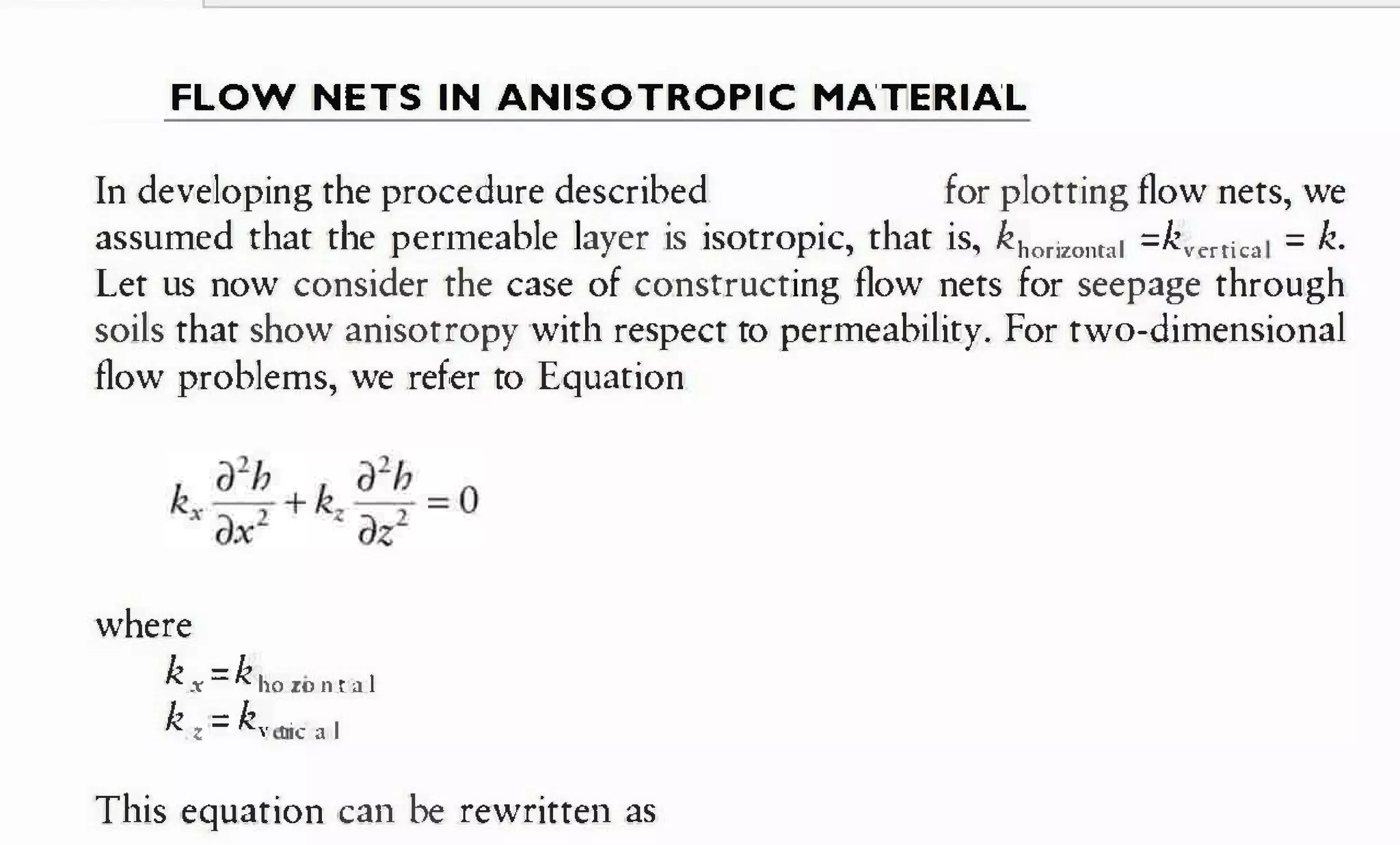
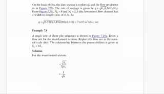
Let x'=/k./Ik,x, then
[x' is the transformed coordinate]](https://image.slidesharecdn.com/17-211108174151/85/17-seepage-through-anisotropic-soil-2-320.jpg)
![. h] m e · l Advanced Soit Mechanics; Fifth Edition Nitro P
r
o - 6 X
File Convert Review Page Layout Forms Share Erase Protect Help login
U m
m
h T ./ a [! (
5
~ 5
A
c
[@Rotate·
3 ·l
I, tat Er beete
zoom
Select T
y
p
e Qui«Sign Request PD
F Combine T
o T
o Highlight nsert
[ 6t
r
a
ct
F
i
n
d A
d
d Customize
T
e
t Signature word D
e
l Note Tools
Tools Create Convert R
evi
ew P
a
g
e layout Document Favorite Tools
D
x
G
I cover •
£
I H
a
it T
i
l
e
I mute Page
l copyright Page
l Dedication
I contents
I Preface
[ Acknowledgments
I Author
a [] 1. soil aggregate, plasticity,
and classification
[ Advanced_Soit_Mechanics_Fifth_Edi.. X
k,
and h
2x10mm/s 1.728 m/day
•
•
k, =4x10mm/s = 3.456 m/day
10 m. For drawing the flow net,
8 [ 2 stresses and strains:
Horizontal
Elastic equilibrium
ffi [] 3 . stresses and
displacements I
n a soil mass:
Two-dimensional problems
8 []4. stresses and
displacements i
n a soil mass:
Three-dimensional problems
8 [ 5 pore w
a
t
e
r Pressure d
u
e
t
o undrained loading
ffi ] 6
. Permeability
a In7. seepage
a le. consolidation
8 [9. shear strength o
f soils
gen
a [ 1o. E
l
a
s
t
i
c settlement o
f
0 shallow foundations
z e [ 1 . consolidation settlement
I ◄ ◄ 298 03
2
1 O
F 7
3
5
► I o 0
II P Search
0 0 g a g + 213%
dimension is reduced by Sqrt.2](https://image.slidesharecdn.com/17-211108174151/85/17-seepage-through-anisotropic-soil-5-320.jpg)


![Geotechnical Engineering-I [Lec #27A: Flow Calculation From Flow Nets]](https://cdn.slidesharecdn.com/ss_thumbnails/27-180924141501-thumbnail.jpg?width=640&height=640&fit=bounds)


