This document provides an overview of filtration theory and processes. It defines filtration as the removal of solids suspended in a liquid by passing the liquid through a porous medium that retains the solids. Various filter types and operating mechanisms are described, including depth filtration, cake filtration, and clarification. Key factors that affect filtration rates such as pressure, viscosity, permeability, and particle size are also discussed. Dimensionless parameters important to modeling filtration like the Reynolds number are introduced.


![Developing a Filtration Model
Iwasaki (1937) developed relationships describing
the performance of deep bed filters.
0=
dC
C
dz
λ−
C is the particle concentration [number/L3]
λ0 is the initial filter coefficient [1/L]
z is the media depth [L]
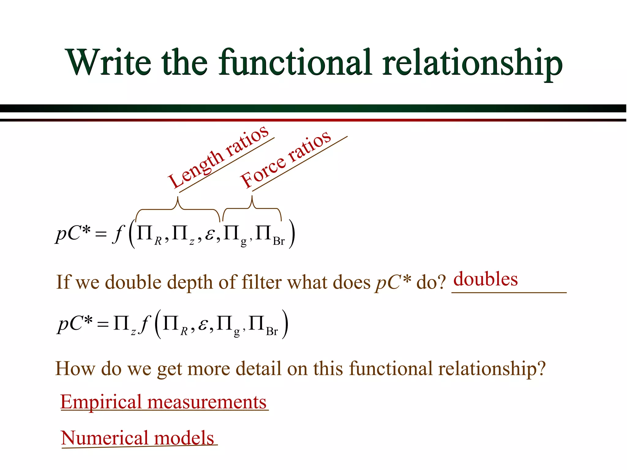
The particle’s chances of being caught are the same at
all depths in the filter; pC* is proportional to depth
0=
dC
dz
C
λ−
0
0
0
=
C z
C
dC
dz
C
λ−∫ ∫ 0
0
ln =
C
z
C
λ
−
( ) 0
0
1
log *
ln 10
C
pC z
C
λ
− = =
0
*
C
C
C
=](https://image.slidesharecdn.com/15-filtration-200630110102/75/15-filtration-30-2048.jpg)


![ Define the following terms:
[Filtration, etc]
Respond to the following questions:
Give a detailed account of ………………
Explain in details the process of …………..
Describe in details with examples the…………
With examples, illustrate the pharmaceutical applications of ……](https://image.slidesharecdn.com/15-filtration-200630110102/75/15-filtration-79-2048.jpg)


![Understanding Parkinson’s Disease: Causes, Symptoms, and Treatment [2025]](https://cdn.slidesharecdn.com/ss_thumbnails/understandingparkinson-251208102525-80ba3223-thumbnail.jpg?width=640&height=640&fit=bounds)


