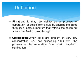
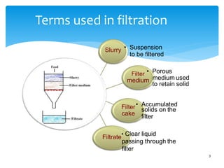
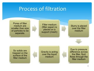
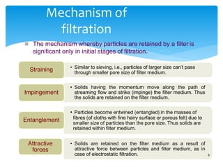
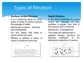
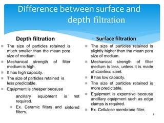
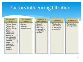
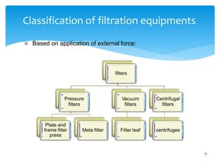
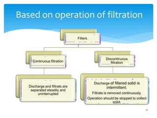
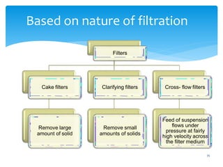
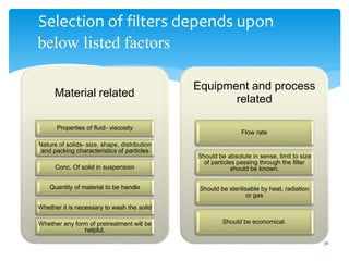
Filtration and Clarification
Samia Ghani
M.Phil Pharmaceutics
Definition
2
 Filtration: It may be define as a process of
separation of solids from a fluid by passing the same
through a porous medium that retains the solids but
allows the fluid to pass through.
solid are present in
 Clarification:When
concentration, i.e., not exceeding 1.0%
very low
w/v, the
is called
process of its separation from liquid
clarification.
Terms used in filtration
cake
Slurry • Suspension
to be filtered
Filter • Porous
medium medium used
to retain solid
Filter• Accumulated
solids on the
filter
Filtrate
• Clear liquid
passing through the
filter
3
Process of filtration
Pores of filter
medium are
smaller than size
of particles to be
separate.
Filter medium
(filter paper) is
placed on a
support (mesh)
Slurry is placed
over the filter
medium
Due to pressure
difference across
the filter, fluid
flows through the
filter medium
Gravity is acting
over the liquid
medium
So solids are
trapped on the
surface of the
filter medium
4
Applications of filtration
5
 Production of sterile products:
 HEPA filters or laminar air bench
 Membrane filters.
 Production of bulk drugs
 Production of liquid dosage
 Effluents and waste water treatment
Mechanism of
filtration
 The mechanism whereby particles are retained by a filter is
significant only in initial stages of filtration.
• Similar to sieving, i.e., particles of larger size can’t pass
through smaller pore size of filter medium.
Straining
• Solids having the momentum move along the path of
streaming flow and strike (impinge) the filter medium. Thus
the solids are retained on the filter medium.
Impingement
• Particles become entwined (entangled) in the masses of
fibres (of cloths with fine hairy surface or porous felt) due to
smaller size of particles than the pore size. Thus solids are
retained within filter medium.
Entanglement
• Solids are retained on the filter medium as a result of
attractive force between particles and filter medium, as in
case of electrostatic filtration.
Attractive
forces
6
Types of filtration
 Surface/ screen filtration
 It is a screening action by which
pores or holes of medium prevent
the passage of solids.
 Mechanism involved : straining
and impingement
 For this, plates with holes or
woven sieves are used.
 Efficacy is defined in terms of
mean or maximum pore size.
gradient density structure
physical restriction or
 Depth filtration
 In this slurry penetrates to a point
where the diameter of solid
particles is greater than that of
the tortuous void or channel.
 Mechanism : Entanglement
 The solids are retained with a
by
by
adsorption properties of medium.
7
Difference between surface and
depth
 Surface filtration
 The size of particles retained is
slightly higher than the mean pore
size of medium.
 Mechanical strength of filter
medium is less, unless it is made
of stainless steel.
 It has low capacity.
 The size of particles retained is
more predictable.
 Equipment is expensive because
ancillary equipment such as edge
clamps is required.
 Ex. Cellulose membrane filter.
8
filtration
Depth filtration
 The size of particles retained is
much smaller than the mean pore
size of medium.
 Mechanical strength of filter
medium is high.
 It has high capacity.
 The size of particles retained is
less predictable.
 Equipment is cheaper because
is not
sintered
ancillary equipment
required.
 Ex. Ceramic filters and
filters.
Theories of filtration
9
 The flow of liquid through a filter follows the basic rules that
govern the flow of any liquid through the medium offering
resistance.
 The rate of flow may be expressed as-
Rate = driving force / resistance
 The rate of filtration may be expressed as volume (litres) per unit
time (dv/dt).
 Driving force = pressure upstream – pressure downstream
 Resistance is not constant.
 It increases with an increase in the deposition of solids on the
filter medium.
 Therefore filtration is not a steady state.
Continue……..
Fig.: Filtration process parameters.
Upstream pressure, P1
 The rate of flow will be greatest at the beginning of filtration
process, since the resistance is minimum.
 After forming of filter cake, its surface acts as filter medium and
solids continuously deposit adding to thickness of the cake.
Powder or granule bed visualized as a bundle of capillaries
Surface area Length (L)
Downstream
pressure, P2
Viscosity
Flow rate:
m3 / unit time
10
 Resistance to flow is related to several factors given in fig.
Resistance to movement={pressure upstream- pressure downstream}/ length of capillaries
Poiseullie’s Equation
 Poiseullie considered that filtration is similar to the streamline
flow of liquid under pressure through capillaries.
 Poiseullie’s Equation is-
 Where, V = rate of flow, m3/s (l/s)
ΔP= Pressure difference across the filter, Pa
r = radius of capillary in the filter bed, m
L = thickness of filter cake (capillary length), m
𝝶= viscosity of filtrate,Pa.s
 If the cake is composed of bulky mass of particles and the liquid
flows through the interstice, then flow of liquids through these
may be expressed by this equation.
11
12
Darcy’s Equation
 Poiseullie's law assumes that the capillaries found in the filter
are highly irregular and non-uniform.
 Therefore, if the length of capillary is taken as the thickness of
bed, a correction factor for radius is applied so that the rate is
closely approximated and simplified.
 The factors influencing the rate of filtration has been
incorporated into an equation by Darcy, which is:
 Where, K = permeability coefficient of cake, m2
A = surface area of porous bed (filter medium), m2
Other terms are same as previous equation
 K depends on characteristics of cake, such as porosity, specific
surface area and compressibility.
13
Continue….
 Permeability may be defined quantitatively as the flow rate of a
liquid of unit viscosity across a unit area of cake having unit
thickness under a pressure gradient of unity.
 This equation is valid for liquids flowing through sand, glass
beds and various porous media.
 This model is applied to filter beds or cakes and other types of
depth filter.
 This equation is further modified by including characteristics of K
by Kozeny-Carman.
Kozeny-Carman (K-C) equation
 Kozeny-Carman equation is widely used for filtration.
 Where,
𝝴
= porosity of cake (bed)
S= specific surface area of particles comprising the cake m2 / m3
K= Kozeny constant (usually taken as 5)
Other terms are same as previousequations
 Limitations:
 It does not consider the fact that depth of granular bed is lesser
than the actual path traversed by the fluid.
 The actual path is not same through out the bed, but it is
sinuous or tortuous. 14
Where:
V= Volume of filtrate
T= Time
A= Filter area
P=Total pressure drop through cake and filter media.
µ= Filtrate viscosity
α= Average specific Cake resistant
W= Weight of dry cake solids.
R=Resistant of filter medium and filter.
16
Factors influencing filtration
Properties of
liquids
• Density
• Viscosity
• corrosiveness
Properties of
solid
• Particle shape
• Particle size
• Particle charge
• Density
• Particle size
distribution
• Rigidity or
compressibility
of solid under
pressure
• Tendency of
particle to
flocculate or
adhere
together
Properties of
solid in slurry
• Rate of
formation of
filter cake
especially in
early stage of
filtration
Objectives
• Whether the
solid or liquid
or both are to
be collected
T
emperature
• Temperature
of suspension
17
Surface area of filter medium
 Rate can be increased either using large filter or connecting a
number of small units in parallel.
 Filter press works on principle of connecting units in parallel.
Rate of
filtration
Inversely proportional to specific surface of filter bed
(According to K-C equation)
Directly proportional to surface area of filter medium
(According to Darcy’s equation)
Pressure drop across the filter medium
17
Gravity
 According to K-C equation the rate of filtration is proportional to
the overall pressure drop across both the filter medium and filter
cake.
 The pressure drop can be achieved in a number of ways:
• A pressure difference could be obtained by maintaining a head of slurry above
the filter medium.
• The pressure developed will depend on the density of the slurry
Vacuum
(Reducing
pressure)
• The pressure below the filter medium may be reduced below atmospheric
pressure by connecting the filtrate receiver to a vacuum pump and creating a
pressure difference across the filter.
Pressure
• The simplest method being to pump the slurry into the filter under pressure.
Centrifugal
force
• The gravitational force could be replaced by centrifugal force in particle
separation
19
Viscosity of filtrate
 According to K-C equation rate of filtration is inversely
proportional to the viscosity of the fluid.
 Reason behind this is an increase in the viscosity of the filtrate
will increase the resistance of flow.
 This problem can be overcome by two methods:
 The rate of filtration may be increased by raising the
temperature of the liquid, which lowers its viscosity. However, it
is not practicable if thermolabile materials are involved or if the
filtrate is volatile.
 Dilution is another alternative but the rate must be doubled.
20
Filter Media
 The surface upon which solids are deposited in a filter is called
the “Filter medium”
 Properties of ideal filter medium:
 It should-
1) be capable of delivering a clear filtrate at a suitable production
rate.
2) have sufficient mechanical strength.
3) be inert.
4) retain the solids without plugging at the start of filtration.
5) Not absorb dissolve material.
6) Sterile filtration imposes a special requirement since the pore
size must not exceed the dimension of bacteria or spores.
Material used as filter media
20
Woven material
• Made up of wool, silk, metal or synthetic fibres (rayon, nylon etc.).
• These include a- wire screening and b- fabrics of cotton, wool, nylon.
• Wire screening e.g. stainless steel is durable, resistance to plugging and easily
cleaned.
• Cotton is a common filter ,however, Nylon is superior for pharmaceutical use,
since it is unaffected by mold, fungus or bacteria and has negligible absorption
properties .
• The choice of fibre depends on chemical
Perforated sheet metal
• Stainless steel plates have pores which act as channels as in case of meta filters.
Bed of granular solid built up on supporting medium
• In some processes, a bed of graded solids may be formed to reduce resistance
of flow.
• Ex. Of granular solids are gravel, sand, asbestos, paper pulp and keiselgur.
• Choice of solids depends on size of solids in process.
Woven Material:
Cotton silk wool nylon & glass etc.
Nylon cloth:
• Superior to the cotton cloth.
• Not affected by molds, fungus and bacteria.
• Has negligible absorption properties.
• It is extremely strong as compared to cotton cloth.
Woven wire cloth:
• Made from stainless steel.
• Easily cleaned.
• Long lasting.
• Resistant to the chemicals.
Cotton Wool:
• Commonly used.
• Small tough of cotton
wool placed in the neck
of funnel.
Glass wool:
• Use for filtering highly
corrosive chemicals.
• May contaminate the
filtrate with glass fibers
Asbestos:
• Also used for filtering
the corrosive liquid.
• They impart alkalinity
to the filtrate.
• Alkaloids may get
absorbed.
• May contaminate the
filtrate.
 Membrane Filter:
• These are very common
among the ultra filtration
methods.
• Made up of cellulose,
Polyvinylchloride, Nylon
and other cellulose
derivatives.
• They rare very fine
having a very vide range
of pore size from 8µ
down to 0.22µ.
Pore size (in µ) Particles removed
0.2 All bacteria
0.45 All coliform group bacteria
0.8 All air born particles
1.2 All Non living particles considered dangerous in I.V.Fluid.
5 All Significant cell from body fluid
 Advantages:
• Bacteria are removed by sieving
• Absorption of medicament is negligible
• In every new operation, a new disc is used
• Filtration is quite rapid
• Don’t liberate particles to the filtrate.
 Disadvantages:
• Fine pores may get clogged easily
• Soluble in certain organic solutions e.g. ketones and esters
• Very brittle when dry.
Craft Paper:
• Mainly used in plate and frame filters.
• They offer controlled porosity
• Limited absorption.
• Quite cheap.
Sintered Glass:
• Consist of Pyrex glass powder.
• Used for filtering parenteral preparations.
• Useful for filtering the corrosive liquid and oxidizing agent.
• Don’t shed particles.
• Don’t absorbs any liquid.
• Can be easily washed.
21
Prefabricated porous solid units
• Used for its convenience and effectiveness.
• Sintered glass, sintered metal, earthenware and porous plastics are used for
fabrication.
Membrane filter media
• These are cartridge units and are economical and available in pore size of 100
μm to even less than 0.2 μm.
• Can be either surface cartridges or depth type cartridges.
• Surface cartridges
• These are corrugated and resin treated papers and used in hydraulic lines.
• Ceramic cartridges and porcelain filter candles are examples.
• Can be reuse after cleaning.
• Depth type cartridges:
• Made up of cotton, asbestos or cellulose.
• These are disposable items, since cleaning is not feasible.
Filter Aids
 The objective of filter aid is to prevent the medium from becoming
blocked and to form an open, porous cake, hence, reducing the
resistance to flow of the filtrate.
 Filter aid forms a surface deposit which screens out the solids and also
prevents the plugging of supporting filter medium.
Characteristics of filter aids:
 Chemically inert and free from impurities.
 Low specific gravity, so remain suspended in liquids.
 Porous rather than dense, so that pervious cake can be formed.
 Recoverable.
Disadvantages:
 Remove the coloured substances by absorbing them.
 Sometimes active principles such as alkaloids are absorbed on filter
aid.
 Rarely, filters are source of contamination such as soluble iron salts,
which can provoke degradation of sensitive ingredient. 22
Handling of filter aids
 Filter aids may be used in either or both two ways:
1) Pre- coating technique: by forming a pre-coat over the filter
medium by filtering a suspension of the filter aid .
2) Body- mix technique: A small proportion of the filter aid (0.1-
0.5 %) is added to the slurry to be filtered. This slurry is
recirculated through the filter until a clear filtrate is obtained,
filtration then proceeds to completion.
 Different flow rates can be achieved depending on grade of
aid-
1. Low flow rate: fine grade filter aids- mainly used for clarity
2.Fast flow rate: coarse grade filter aids- acceptable filtrate.
Examples of filter aids
 Diatomite (Keiselgur) , obtained from natural siliceous deposits.
 Perlite , it is an aluminium silicate. Cellulose,
charcoal, talc, bentonite , fullers earth etc.
Asbestos,
23
Materials Chemical
composition
Advantages Disadvantages
Diatomaceous earth Silica Wide size range Slightly soluble in
acid and alkalies
Perlite Silica
+Aluminosilicate
Wide size range More soluble
Asbestose Aluminosilicate Very good retaintion
on coarse screen
More soluble
Cellulose Cellulose Chemically inert Expensive
Carbon Carbon Non reactive with
strong alkalies
Expensive
ASBESTOSE CELLULOSE CARBON
DIATOMACEOUS EARTH PERLITE
33
Classification of filtration equipments
 Based on application of external force:
filters
Pressure
filters
Plate and
frame filter
press
Meta filter
Vacuum
filters
Filter leaf
Centrifugal
filters
centrifuges
34
Based on operation of filtration
Filters
Continuous filtration
Discharge and filtrate are
separated steadily and
uninterrupted
Discontinuous
filtration
Discharge of filtered solid is
intermittent.
Filtrate is removed continuously.
Operation should be stopped to collect
solid.
35
Based on nature of filtration
Filters
Cake filters
Remove large
amount of solid
Clarifying filters
Remove small
amounts of solids
Cross- flow filters
Feed of suspension
flows under
pressure at fairly
high velocity across
the filter medium
Selection of filters depends upon
36
below listed factors
Material related
Properties of fluid- viscosity
Nature of solids- size, shape, distribution
and packing characteristics of particles
Conc. Of solid in suspension
Quantity of material to be handle
Whether it is necessary to wash the solid
Whether any form of pretreatment will be
helpful.
Equipment and process
related
Flow rate
Should be absolute in sense, limit to size
of particles passing through the filter
should be known.
Should be sterilisable by heat, radiation
or gas
Should be economical.
37
Laboratory scale filtration
 Filter paper and funnel
 Buchner funnel and filter paper
 Sintered glass filter
 Seitz filter
 Membrane filter
FILTER FUNNEL:
• Funnels are conical shaped
devices
• Made up of Glass,
Aluminum, Polythene,
Stainless steel OR any
other suitable material.
• Neutral Glass made funnel
are most commonly used.
• White filter paper of
suitable pore size is folded
in such a way that it fits in
the funnel.
BUCHNER FUNNEL:
• Made up of porcelain.
• It has a perforated plate.
• Used for filtration under reduced
pressure.
HOT WATER FUNNEL:
• These are doubled wall funnels
made up of metals.
• Viscous substances such as liquid
paraffin, Glycerin, Castor oil and
fatty substances like wool fat, bees
wax, ointments and cream etc are
filtered easily from this filter.
• Boiling water or steam is
circulated in jacketed funnel.
SEITZ FILTER:
• Consists of two parts.
• Lower part fitted with a perforated plate over
which compressed asbestos pad is placed.
• Upper part has a value through which
pressure can be applied.
• Both parts joined together by winged nuts.
 Advantages:
• No risk of contaminating the filtrate.
• Apparatus is very simple to use.
• For viscous solution they are more suitable.
 Disadvantages:
• Asbestos may shed loose fibers.
• Pad may absorbs sufficient amount of
medicament.
FILTER PRESS:
• It consists of hollow frames and solid plates.
• Plates have grooved surface to support the filter cloth.
• Each plate has an outlet for filtrate.
• Frames are opened with an inlet for the liquid to be
filtered.
Advantages:
• Construction is very simple.
• Used for coarse to fine filtration.
• Operation and maintenance is easy.
• Filter cloth can be easily replaced.
Disadvantages:
• Not economical for filtration of small quantities
• Leakage between the plates may take place
• Suitable when the slurry contain less than 5%
solids.
 Principle:
 Mechanism is surface filtration.
 The slurry enters the frame by pressure and flows
through filter medium.
 The filtrate is collected on the plates and send to
outlet.
 A number of frames and plates are used so that
surface area increases and consequently large
volumes of slurry can be processed simultaneously
with or without washing.
43
Plate and frame filter press
Diagram
44
Assembly of plate and frame filter
45
46
Construction
 The Filter press is made of two types of units, plate and frames.
 Usually made of aluminium alloy.
 Sometimes, these are also lacquered for protection against
corrosive chemicals and made suitable for steam sterilization.
 Frame
 It contains a open space inside wherein the slurry reservoir is
maintained for filtration
Slurry inlet
Handle to rest on rod
47
Continue….
 Frames of different thickness are available.
 It is selected based on the thickness of cake formed during
filtration.
 Optimum thickness of frame should be chosen.
 Plate
 The plate has a studded or grooved surface to support the filter
cloth and an outlet.
Through channel
Filtrate outlet
48
Continue……
Slurry enters the frame
from the feed channel and
passes through the filter
medium on the surface of
the plate
The solid forms a filter cake
and remain in the frame
The thickness of the cake
is half of the frame
thickness, because on
each side of frame filtration
occurs
Thus two filter cakes are
formed , which meet
eventually in the centre of
the frame
The filtrate drains between
the projections of the
surface of the plate and
escape from the outlet
As filtration proceeds, the
resistance of the cake
increases and filtration rate
decrease
At a certain point process is
stopped and press is
emptied and cycle is
restarted
 Special provisions:
 1. Any possible contamination can be observed by
passing the filtrate through a glass tube or sight glass
from the outlet on each plate. This permits the
inspection of quality of filtrate.
 In the event of broken cloth, the faulty plate can be
isolated and filtration can be continued with one
plate less.
 Uses:
 Sterile filtrate can by obtain by using asbestos and
cellulose filter sheet (for this, whole filter press and
filter medium have been sterilized previously).
Special provisions and Uses
41
Advantages:
• Labour costs are very low.
• Area of filtration is very high.
• Thickness of the filtration cake is controlled by
altering with the speed of rotation of drum.
51
Disadvantages
 It is a batch filter, so it is a time consuming.
 The filter press is an expensive filter, the emptying time, the
labour involved, and the wear and tear on the cloths resulting in
high costs.
 Operation is critical, as the frames should be full, otherwise
washing is inefficient and the cake is difficult to remove.
 In view of the high labour costs , it is most suitable for expensive
materials only e.g. the removal of precipitated proteins from
insulin liquors.
 Can’t be used for slurries containing low percentage of solids.
52
Chamber press
Principle
 Mechanism is surface filtration.
 The slurry enters the frame by pressure and flows through the
filter cloth.
 The filtrate is collected on the plates and send to the outlet.
 A number of head plates are used, so that the surface area can
be increases and consequently large volumes of slurry can be
processed simultaneously.
Diagram
53
 It consist of heavy fixed head plate made of cast iron and mounted on
 suitable frame.
 Extending from the head plate, two horizontal bars support on both
ends.
 The bar supports the plate by lugs.
 At the center of the each plate, a hole is provided for introducing the
 feed.
 The holes of the all plate are connected on the head of the press.
 Over each press plate, a sheet of filter cloth with a hole cut in the centre
and is placed.
 The filter cloth is fastened by means of rings called grommets and
 either screwed together or locked.
 These draw down the cloth, so that it is shaped round the plate.
 All such plates are arranged and a heavy follower plate is
placed behind and tighten.
Construction
 The cloth serves as a gasket between the adjacent plates. 46
Working
55
The slurry is pumped
through the hole
connected at the
centre.
The slurry passes
through the cloth
Runs down the
corrugations on the
face of the plates and
escape through the
holes cored in the
bottom of each plate
The filtrate passes
through the outlet
The external outlet
usually discharges into
an open launder.
The space between
the plates is the
volume available for
the formation of cake
When sufficient cake is
accumulated in the
chamber , the closing
screw is released
The plates are
dismantled and the
cake is discharged
Then, the plates are
reassembled.
56
Uses, advantages and
disadvantages
Uses:
 used for clarification of syrups and filtrating of injection solutions.
Advantages:
 Provide large filtering area in relatively small floor space.
 A number of head plates can be increased or decreased as per
need.
 Operation and maintenance are straight forward (no moving part).
 Filter cloths are easily renewable.
Disadvantages:
 Not adaptable for washing of cake.
 The wear of cloth is severe.
 The filtrate is usually not clear.
 Principle:
 Mechanism is surface filtration.
 In this, metal rings contain semicircular projections,
which are arranged as a nest to form channels on the
edges.
 This channeloffers resistance (strainer) to the flow
of solids (coarse particles).
 The clear liquid is collected into receiver from the top.
57
Metafilter
58
Construction
 Metafilter consists of a series of metal rings.
 These are threaded so that a channel is formed on the edges.
 It contains a grooved drainage column on which a series of
metal rings are packed.
 These rings are usually made up of stainless steel and have
dimensions of about 15.0 mm internal diameter and 22.0 mm
external diameter.
 Each metal ring has a number of semicircular projections (0.8
mm in thickness) on one side of surface.
 The projections are arranged as a nest to form channels on the
edges.
 These rings are tightened on the drainage column with a nut.
 Metafilters are also known as edge filters.
Diagram
59
60
Working
Filters are placed in
a vessel
Slurry is pumped
under pressure or
occasionally by
applying reduced
pressure to the
outlet side
Slurry passes
through the
channels formed on
the edges between
the rings
The clear liquid
rises up and
collected from the
outlet into receiver
 For separation of fine particles, a bed of suitable materials
such kieselguhr is first built up.
 The pack of rings serves essentially as a base on which the
true filter medium is supported.
61
Uses
can be achieved by applying
 Metafilters can be used for-
 Clarification of syrups
 Filtration of injection solutions
 Clarification of insulin liquors
 Filtration of viscous liquids
pressure.
62
Advantages
 Can be used under high pressures, without any danger of
bursting the filter medium.
 Running cost are low, as separate filter medium is not used.
 Can be constructed from a material that can provide excellent
resistance to corrosion and avoid contamination of sensitive
products.
 It is extremely versatile filter because fine as well as large both
type of particles can be separated.
 Removal of cake can be carried out by simply back- flushing
with water.
 Change over from one batch to another or one product to
another is easy.
 Sterile products can be handled.
VACUUM FILTRATION:
• Vacuum filtration is used primarily to collect a
desired solid.
• Vacuum filtration uses a Buchner funnel and a side-
arm flask.
• Vacuum filtration is faster than gravity filtration
because air is forced through the filter paper by the
application of reduced pressure.
To perform a vacuum
filtration:
• Clamp the flask securely to a
ring stand.
• Add a Buchner funnel with a
rubber funnel adaptor.
• Obtain a piece of filter paper
in the funnel that is small
enough to remain flat but
large enough to cover all of
the holes in
necessary, you can cut
the filter. If
a
larger piece of filter paper
down to size.
• Place the paper in the
funnel.
• Connect the side arm flask
vacuum source.
use thick-walled
to a
Always
tubes.
• Wet the paper with a small
amount of the solvent to
be used in the filtration.
This causes the paper to
to the plate and
materials from
adhere
keeps
passing under the paper
during filtration.
• Turn on the vacuum
source.
• Pour the mixture to be
filtered onto the filter
paper. The vacuum
should rapidly pull the
liquid through the
funnel.
• Rinse the cake with a
small amount of cold
fresh solvent to help
remove impurities that
were dissolved in the
filtrate.
• Carefully disconnect
the rubber tube.
• Remove
paper
the filter
and the
collected solid that is
on it.
68
Filter leaf
Principle:
 It is an apparatus consisting of a longitudinal drainage screen
covered with a filter cloth.
 The mechanism is surface filtration and acts as sieve or strainer.
 Vacuum or pressure can be applied to increase the rate of
filtration.
Construction:
 The leaf filter is consisting of a frame enclosing a drainage
screen or grooved plate.
 The frame may be any shape circular, square or rectangular.
 The whole unit being covered with filter cloth.
 The outlet for the filtrate connects to the inside of the frame
through suction.
Diagram
69
70
Working and uses
Working:
Use:
 Use for the filtration of slurry which do not contain high solid
content, about 5%, i.e. dilute suspensions.
The filter leaf
is immersed
in the slurry
Vacuum
system is
connected to
the outlet
The slurry
passes
through the
filter cloth
Finally
filtrate enters
the drainage
canal and
goes through
the outlet
into receiver
Air is passed
to flow in
reverse
direction
which
facilitates
removal of
cake
71
Advantages
 Simplest form of filter used for batch process.
 A number of units can be connected in parallel to increase the
surface area of filtration.
 Pressure difference can be obtained either with vacuum or using
pressure up to the order of 800 kilopascals.
 Labour costs for operating the filter leaf are fairly moderate.
 The efficiency of washing is high.
 The slurry can be filtered from any vessel.
 The cake can be washed simply by immersing the filter in a
vessel of Water.
72
Sweetland filter (variant of filter
leaf)
 An alternative method is to enclose the filter leaf in a special
vessel into which the slurry is pumped under pressure.
 A number of leaves are connected to a common outlet, to
provide a large area for filtration.
Cartridge filter
Principle:
 It is a thin porous membrane in which pre filter and membrane filter are
combined in a single unit.
 The filtration action is mainly sieve like and particles are retained on the
surface.
Construction:
 It has cylindrical configuration made with disposable or changeable
filter media.
 Made up of either plastic or metal.
 Consist of two membrane filters (sieve like) made of polypropylene: pre
filter and actual filter for filtration.
 A protective layer surrounds them.
 The cartridge are housed in a holder and a number of cartridges can be
placed in a same housing.
 The housing is closed with the lid.
 Housing has provisions for slurry inlet and outlets. 60
Diagram
74
75
Working and uses
Working:
Uses:
 Particularly useful for preparation of particulate free solutions for
parenterals and ophthalmic uses.
 This filter holder will process 1000 – 15000 litres of sterile
solution per hour.
Slurry is
pumped
into
cartridge
holder
It passes
through
cartridge
filter unit
by
straining
The clear
liquid
passes
through
the
centre
Moves
up to
collect
through
outlet
76
Advantages and Disadvantages
Advantages:
 Autoclaving can be done for sterile operations due to stainless
steel construction.
 Cartridge with self cleaning devices are advantageous.
 Rapid disassembling as well as reusing of filter medium is
possible.
 Cartridge are not brittle, when they are dry.
 Used as in-line continuous filtration, which reduces handling of
solutions. It minimize chances of contaminations.
Disadvantages:
 A number of manufactures provide the components, which are
generally not interchangeable between suppliers.
 Cost of disposable elements offsets the labour saving in terms
of assembly and cleaning of cartridge clarifiers.
ROTARY FILTERS:
• They are used when the proportion of solid content in slurry is 15 to
30%.
• It consists of perforated matter drum wrapped with filter cloth.
• Drum is partially immersed in the tank containing the materials to
be filtered.
• Drum rotates at the slow speed and creates vacuum due to which
filtrate enters into the drum.
• Filter cake deposits on outer surface of the filter media.
• Cake is removed by scrapping with a knife.
 The rotary filter for continuous operation on large
quantities of slurry.
 Suitable for slurry contains considerable amounts of
solids in the range 15-30%.
 Examples of pharmaceutical application include
 the collection of calcium carbonate, magnesium
carbonate, and starch.
 The separation of the mycelium from the fermentation
liquor in the manufacture of antibiotics.
78
Uses
79
Advantages
 The rotary filter is automatic and is continuous in operation, so
that the labour costs are very low.
 The filter has a large capacity , so it is suitable for the filtration of
highly concentrated solutions.
 Variation of the speed of rotation enables the cake thickness to
be controlled.
 Pre-coat of filter aid could used to accelerate the filtration rate.
 Filter has large surface area.
 The rotary filter is a complex piece of equipment , with
many moving parts and is very expensive.
 In addition to the filter itself, some accessories are
connected ,e.g., a vacuum pump, vacuum receivers,
slurry pumps and agitators are required .
 The cake tends to crack due to the air drawn
through by the vacuum system, so that washing and
drying are notefficient.
 Being a vacuum filter, the pressure difference is
limited to 1 bar and hot filtrates may boil.
 It is suitable only for straight- forward slurries
Disadvantages
81
Pressure and sand filter
Principle:
 Depth filtration
 Mechanism is impingement and entanglement of solids on
account of low pressure differential.
 The slurry enters the sand bed and the clear liquid is collected
from the bottom outlet.
82
Construction
 It is a closed system and consists of cylindrical tank with a
bottom containing a number of brass strainers.
 These are mounted on false bottom or connected to a modified
embedded in concrete.
 The strainers have narrow slots sawed in them.
 Above this 6-12 m depth sand layer is placed, which acts as a
filter medium.
 Baffles are arranged at the point of feed inlet, in order to prevent
the disturbance of sand by direct stream.
 Provisions is made at the bottom for collecting the filtrate.
83
Working
The feed is introduced
from the top at
pressure through the
baffles.
The feed is passed
smoothly at a uniform
rate onto the sand
medium
Filtration is achieved
by straining
mechanism through
sand medium
Then, the feed is
passed through the
strainer, so that further
filtration takes place
and particles are
retained
The precipitate is
discarded
The filtrate is collected
fro bottom
84
Continue…..
 When the precipitate clogs the sand (indicated by reduced
filtration rate), back washing permits the regeneration of the filter
bed.
 During this operation, water moves up through the sand bed and
moves out from the inlet.
Uses:
 Used for filtration of boiler feed or water for similar purposes.
 Mainly used when solids are little and large volume of feed is to
be handled.
 They are applicable only to the separation of precipitates that
can be removed from the sand.
85
Disadvantages
 Feed containing precipitates that are gelatinous or form a coat
on sand can’t be filtered through the sand, because back
washing does not permit regeneration.
 Feed containing finely divided solids can’t be separate by this.
 Can’t remove bacteria. In such cases, coagulants such as
ferrous sulphate, are added to feed before filtration.
86
Streamline filter
Principle:
 It consists of column of filter elements held tightly together, so
that the slurry enters from the side of the column and passes
through vary narrow channels between the elements.
 The filters employ paper discs.
 The filter act as a strainer to retain solids.
87
Assembly
 It consists of specially treated filter paper discs arranged in the
form of a compressed pack on an upright rod or spigot.
 In assembling the filter, the two parts of the filter can be
unscrewed.
 The required quantity of rings are placed on the spigot portion
and two parts are then screwed together to give a compact
stack of filter elements.
 The extent of compression on the disc may be varied depending
on the size of particles to be removed.
 For small scale filtration, ebonite material made spigots are
used.
 The spigot is hollow and grooves run down the length.
 From hollow centre of the spigot, vacuum is applied.
88
Working
Filter is immersed in the
liquid to be filtered
From the hollow centre
of spigot vacuum is
applied
The roughness of the
paper surfaces offer
narrow passage ways
through which clear
liquid flows
Further, liquid also
passes between the
surface of the paper
discs
The entire solid residue
is left at the edge and
width of the pack
The clear liquid passes
through the grooves,
sucked through the
hollow centre of spigot
and filtrate passes to the
receiver
After the last quantity of
liquid is filtered, wash
water may be used
89
Continue….
 Cleaning of streamline filter is attempted by connecting the
spigot to the water tap.
 The water is passed in opposite direction.
 The residue is washed away from the edges of the stack.
 If solid residue is required, air may be blown, so that solid is
peeled of, which may be collected.
90
Uses and Advantages
Uses:
 It removes suspended matter, trace of fines and even submicron
size colloidal matter from large volumes of the slurry.
 The two parts of spigots are screwed tightly and fine precipitates
can be separated for achieving high grade polishing.
 Oily, aqueous and alcoholic solutions which do not soften the
fibre of the pack can also be filtered.
 Heat resistant porcelain filters are used for strongly acidic or hot
strong alkaline solutions.
Advantages:
 Instead of vacuum, pressure may be applied.
 In this case, the container (in which assembly is immersed)
must be sealed and should be able to withstand applied
pressure.

Filtration and clarification

  • 1.
    Filtration and Clarification SamiaGhani M.Phil Pharmaceutics
  • 2.
    Definition 2  Filtration: Itmay be define as a process of separation of solids from a fluid by passing the same through a porous medium that retains the solids but allows the fluid to pass through. solid are present in  Clarification:When concentration, i.e., not exceeding 1.0% very low w/v, the is called process of its separation from liquid clarification.
  • 3.
    Terms used infiltration cake Slurry • Suspension to be filtered Filter • Porous medium medium used to retain solid Filter• Accumulated solids on the filter Filtrate • Clear liquid passing through the filter 3
  • 4.
    Process of filtration Poresof filter medium are smaller than size of particles to be separate. Filter medium (filter paper) is placed on a support (mesh) Slurry is placed over the filter medium Due to pressure difference across the filter, fluid flows through the filter medium Gravity is acting over the liquid medium So solids are trapped on the surface of the filter medium 4
  • 5.
    Applications of filtration 5 Production of sterile products:  HEPA filters or laminar air bench  Membrane filters.  Production of bulk drugs  Production of liquid dosage  Effluents and waste water treatment
  • 6.
    Mechanism of filtration  Themechanism whereby particles are retained by a filter is significant only in initial stages of filtration. • Similar to sieving, i.e., particles of larger size can’t pass through smaller pore size of filter medium. Straining • Solids having the momentum move along the path of streaming flow and strike (impinge) the filter medium. Thus the solids are retained on the filter medium. Impingement • Particles become entwined (entangled) in the masses of fibres (of cloths with fine hairy surface or porous felt) due to smaller size of particles than the pore size. Thus solids are retained within filter medium. Entanglement • Solids are retained on the filter medium as a result of attractive force between particles and filter medium, as in case of electrostatic filtration. Attractive forces 6
  • 7.
    Types of filtration Surface/ screen filtration  It is a screening action by which pores or holes of medium prevent the passage of solids.  Mechanism involved : straining and impingement  For this, plates with holes or woven sieves are used.  Efficacy is defined in terms of mean or maximum pore size. gradient density structure physical restriction or  Depth filtration  In this slurry penetrates to a point where the diameter of solid particles is greater than that of the tortuous void or channel.  Mechanism : Entanglement  The solids are retained with a by by adsorption properties of medium. 7
  • 8.
    Difference between surfaceand depth  Surface filtration  The size of particles retained is slightly higher than the mean pore size of medium.  Mechanical strength of filter medium is less, unless it is made of stainless steel.  It has low capacity.  The size of particles retained is more predictable.  Equipment is expensive because ancillary equipment such as edge clamps is required.  Ex. Cellulose membrane filter. 8 filtration Depth filtration  The size of particles retained is much smaller than the mean pore size of medium.  Mechanical strength of filter medium is high.  It has high capacity.  The size of particles retained is less predictable.  Equipment is cheaper because is not sintered ancillary equipment required.  Ex. Ceramic filters and filters.
  • 9.
    Theories of filtration 9 The flow of liquid through a filter follows the basic rules that govern the flow of any liquid through the medium offering resistance.  The rate of flow may be expressed as- Rate = driving force / resistance  The rate of filtration may be expressed as volume (litres) per unit time (dv/dt).  Driving force = pressure upstream – pressure downstream  Resistance is not constant.  It increases with an increase in the deposition of solids on the filter medium.  Therefore filtration is not a steady state.
  • 10.
    Continue…….. Fig.: Filtration processparameters. Upstream pressure, P1  The rate of flow will be greatest at the beginning of filtration process, since the resistance is minimum.  After forming of filter cake, its surface acts as filter medium and solids continuously deposit adding to thickness of the cake. Powder or granule bed visualized as a bundle of capillaries Surface area Length (L) Downstream pressure, P2 Viscosity Flow rate: m3 / unit time 10  Resistance to flow is related to several factors given in fig. Resistance to movement={pressure upstream- pressure downstream}/ length of capillaries
  • 11.
    Poiseullie’s Equation  Poiseullieconsidered that filtration is similar to the streamline flow of liquid under pressure through capillaries.  Poiseullie’s Equation is-  Where, V = rate of flow, m3/s (l/s) ΔP= Pressure difference across the filter, Pa r = radius of capillary in the filter bed, m L = thickness of filter cake (capillary length), m 𝝶= viscosity of filtrate,Pa.s  If the cake is composed of bulky mass of particles and the liquid flows through the interstice, then flow of liquids through these may be expressed by this equation. 11
  • 12.
    12 Darcy’s Equation  Poiseullie'slaw assumes that the capillaries found in the filter are highly irregular and non-uniform.  Therefore, if the length of capillary is taken as the thickness of bed, a correction factor for radius is applied so that the rate is closely approximated and simplified.  The factors influencing the rate of filtration has been incorporated into an equation by Darcy, which is:  Where, K = permeability coefficient of cake, m2 A = surface area of porous bed (filter medium), m2 Other terms are same as previous equation  K depends on characteristics of cake, such as porosity, specific surface area and compressibility.
  • 13.
    13 Continue….  Permeability maybe defined quantitatively as the flow rate of a liquid of unit viscosity across a unit area of cake having unit thickness under a pressure gradient of unity.  This equation is valid for liquids flowing through sand, glass beds and various porous media.  This model is applied to filter beds or cakes and other types of depth filter.  This equation is further modified by including characteristics of K by Kozeny-Carman.
  • 14.
    Kozeny-Carman (K-C) equation Kozeny-Carman equation is widely used for filtration.  Where, 𝝴 = porosity of cake (bed) S= specific surface area of particles comprising the cake m2 / m3 K= Kozeny constant (usually taken as 5) Other terms are same as previousequations  Limitations:  It does not consider the fact that depth of granular bed is lesser than the actual path traversed by the fluid.  The actual path is not same through out the bed, but it is sinuous or tortuous. 14
  • 15.
    Where: V= Volume offiltrate T= Time A= Filter area P=Total pressure drop through cake and filter media. µ= Filtrate viscosity α= Average specific Cake resistant W= Weight of dry cake solids. R=Resistant of filter medium and filter.
  • 16.
    16 Factors influencing filtration Propertiesof liquids • Density • Viscosity • corrosiveness Properties of solid • Particle shape • Particle size • Particle charge • Density • Particle size distribution • Rigidity or compressibility of solid under pressure • Tendency of particle to flocculate or adhere together Properties of solid in slurry • Rate of formation of filter cake especially in early stage of filtration Objectives • Whether the solid or liquid or both are to be collected T emperature • Temperature of suspension
  • 17.
    17 Surface area offilter medium  Rate can be increased either using large filter or connecting a number of small units in parallel.  Filter press works on principle of connecting units in parallel. Rate of filtration Inversely proportional to specific surface of filter bed (According to K-C equation) Directly proportional to surface area of filter medium (According to Darcy’s equation)
  • 18.
    Pressure drop acrossthe filter medium 17 Gravity  According to K-C equation the rate of filtration is proportional to the overall pressure drop across both the filter medium and filter cake.  The pressure drop can be achieved in a number of ways: • A pressure difference could be obtained by maintaining a head of slurry above the filter medium. • The pressure developed will depend on the density of the slurry Vacuum (Reducing pressure) • The pressure below the filter medium may be reduced below atmospheric pressure by connecting the filtrate receiver to a vacuum pump and creating a pressure difference across the filter. Pressure • The simplest method being to pump the slurry into the filter under pressure. Centrifugal force • The gravitational force could be replaced by centrifugal force in particle separation
  • 19.
    19 Viscosity of filtrate According to K-C equation rate of filtration is inversely proportional to the viscosity of the fluid.  Reason behind this is an increase in the viscosity of the filtrate will increase the resistance of flow.  This problem can be overcome by two methods:  The rate of filtration may be increased by raising the temperature of the liquid, which lowers its viscosity. However, it is not practicable if thermolabile materials are involved or if the filtrate is volatile.  Dilution is another alternative but the rate must be doubled.
  • 20.
    20 Filter Media  Thesurface upon which solids are deposited in a filter is called the “Filter medium”  Properties of ideal filter medium:  It should- 1) be capable of delivering a clear filtrate at a suitable production rate. 2) have sufficient mechanical strength. 3) be inert. 4) retain the solids without plugging at the start of filtration. 5) Not absorb dissolve material. 6) Sterile filtration imposes a special requirement since the pore size must not exceed the dimension of bacteria or spores.
  • 21.
    Material used asfilter media 20 Woven material • Made up of wool, silk, metal or synthetic fibres (rayon, nylon etc.). • These include a- wire screening and b- fabrics of cotton, wool, nylon. • Wire screening e.g. stainless steel is durable, resistance to plugging and easily cleaned. • Cotton is a common filter ,however, Nylon is superior for pharmaceutical use, since it is unaffected by mold, fungus or bacteria and has negligible absorption properties . • The choice of fibre depends on chemical Perforated sheet metal • Stainless steel plates have pores which act as channels as in case of meta filters. Bed of granular solid built up on supporting medium • In some processes, a bed of graded solids may be formed to reduce resistance of flow. • Ex. Of granular solids are gravel, sand, asbestos, paper pulp and keiselgur. • Choice of solids depends on size of solids in process.
  • 22.
    Woven Material: Cotton silkwool nylon & glass etc. Nylon cloth: • Superior to the cotton cloth. • Not affected by molds, fungus and bacteria. • Has negligible absorption properties. • It is extremely strong as compared to cotton cloth. Woven wire cloth: • Made from stainless steel. • Easily cleaned. • Long lasting. • Resistant to the chemicals.
  • 23.
    Cotton Wool: • Commonlyused. • Small tough of cotton wool placed in the neck of funnel. Glass wool: • Use for filtering highly corrosive chemicals. • May contaminate the filtrate with glass fibers
  • 24.
    Asbestos: • Also usedfor filtering the corrosive liquid. • They impart alkalinity to the filtrate. • Alkaloids may get absorbed. • May contaminate the filtrate.
  • 25.
     Membrane Filter: •These are very common among the ultra filtration methods. • Made up of cellulose, Polyvinylchloride, Nylon and other cellulose derivatives. • They rare very fine having a very vide range of pore size from 8µ down to 0.22µ.
  • 26.
    Pore size (inµ) Particles removed 0.2 All bacteria 0.45 All coliform group bacteria 0.8 All air born particles 1.2 All Non living particles considered dangerous in I.V.Fluid. 5 All Significant cell from body fluid  Advantages: • Bacteria are removed by sieving • Absorption of medicament is negligible • In every new operation, a new disc is used • Filtration is quite rapid • Don’t liberate particles to the filtrate.  Disadvantages: • Fine pores may get clogged easily • Soluble in certain organic solutions e.g. ketones and esters • Very brittle when dry.
  • 27.
    Craft Paper: • Mainlyused in plate and frame filters. • They offer controlled porosity • Limited absorption. • Quite cheap. Sintered Glass: • Consist of Pyrex glass powder. • Used for filtering parenteral preparations. • Useful for filtering the corrosive liquid and oxidizing agent. • Don’t shed particles. • Don’t absorbs any liquid. • Can be easily washed.
  • 28.
    21 Prefabricated porous solidunits • Used for its convenience and effectiveness. • Sintered glass, sintered metal, earthenware and porous plastics are used for fabrication. Membrane filter media • These are cartridge units and are economical and available in pore size of 100 μm to even less than 0.2 μm. • Can be either surface cartridges or depth type cartridges. • Surface cartridges • These are corrugated and resin treated papers and used in hydraulic lines. • Ceramic cartridges and porcelain filter candles are examples. • Can be reuse after cleaning. • Depth type cartridges: • Made up of cotton, asbestos or cellulose. • These are disposable items, since cleaning is not feasible.
  • 29.
    Filter Aids  Theobjective of filter aid is to prevent the medium from becoming blocked and to form an open, porous cake, hence, reducing the resistance to flow of the filtrate.  Filter aid forms a surface deposit which screens out the solids and also prevents the plugging of supporting filter medium. Characteristics of filter aids:  Chemically inert and free from impurities.  Low specific gravity, so remain suspended in liquids.  Porous rather than dense, so that pervious cake can be formed.  Recoverable. Disadvantages:  Remove the coloured substances by absorbing them.  Sometimes active principles such as alkaloids are absorbed on filter aid.  Rarely, filters are source of contamination such as soluble iron salts, which can provoke degradation of sensitive ingredient. 22
  • 30.
    Handling of filteraids  Filter aids may be used in either or both two ways: 1) Pre- coating technique: by forming a pre-coat over the filter medium by filtering a suspension of the filter aid . 2) Body- mix technique: A small proportion of the filter aid (0.1- 0.5 %) is added to the slurry to be filtered. This slurry is recirculated through the filter until a clear filtrate is obtained, filtration then proceeds to completion.  Different flow rates can be achieved depending on grade of aid- 1. Low flow rate: fine grade filter aids- mainly used for clarity 2.Fast flow rate: coarse grade filter aids- acceptable filtrate. Examples of filter aids  Diatomite (Keiselgur) , obtained from natural siliceous deposits.  Perlite , it is an aluminium silicate. Cellulose, charcoal, talc, bentonite , fullers earth etc. Asbestos, 23
  • 31.
    Materials Chemical composition Advantages Disadvantages Diatomaceousearth Silica Wide size range Slightly soluble in acid and alkalies Perlite Silica +Aluminosilicate Wide size range More soluble Asbestose Aluminosilicate Very good retaintion on coarse screen More soluble Cellulose Cellulose Chemically inert Expensive Carbon Carbon Non reactive with strong alkalies Expensive
  • 32.
  • 33.
    33 Classification of filtrationequipments  Based on application of external force: filters Pressure filters Plate and frame filter press Meta filter Vacuum filters Filter leaf Centrifugal filters centrifuges
  • 34.
    34 Based on operationof filtration Filters Continuous filtration Discharge and filtrate are separated steadily and uninterrupted Discontinuous filtration Discharge of filtered solid is intermittent. Filtrate is removed continuously. Operation should be stopped to collect solid.
  • 35.
    35 Based on natureof filtration Filters Cake filters Remove large amount of solid Clarifying filters Remove small amounts of solids Cross- flow filters Feed of suspension flows under pressure at fairly high velocity across the filter medium
  • 36.
    Selection of filtersdepends upon 36 below listed factors Material related Properties of fluid- viscosity Nature of solids- size, shape, distribution and packing characteristics of particles Conc. Of solid in suspension Quantity of material to be handle Whether it is necessary to wash the solid Whether any form of pretreatment will be helpful. Equipment and process related Flow rate Should be absolute in sense, limit to size of particles passing through the filter should be known. Should be sterilisable by heat, radiation or gas Should be economical.
  • 37.
    37 Laboratory scale filtration Filter paper and funnel  Buchner funnel and filter paper  Sintered glass filter  Seitz filter  Membrane filter
  • 38.
    FILTER FUNNEL: • Funnelsare conical shaped devices • Made up of Glass, Aluminum, Polythene, Stainless steel OR any other suitable material. • Neutral Glass made funnel are most commonly used. • White filter paper of suitable pore size is folded in such a way that it fits in the funnel.
  • 39.
    BUCHNER FUNNEL: • Madeup of porcelain. • It has a perforated plate. • Used for filtration under reduced pressure. HOT WATER FUNNEL: • These are doubled wall funnels made up of metals. • Viscous substances such as liquid paraffin, Glycerin, Castor oil and fatty substances like wool fat, bees wax, ointments and cream etc are filtered easily from this filter. • Boiling water or steam is circulated in jacketed funnel.
  • 40.
    SEITZ FILTER: • Consistsof two parts. • Lower part fitted with a perforated plate over which compressed asbestos pad is placed. • Upper part has a value through which pressure can be applied. • Both parts joined together by winged nuts.  Advantages: • No risk of contaminating the filtrate. • Apparatus is very simple to use. • For viscous solution they are more suitable.  Disadvantages: • Asbestos may shed loose fibers. • Pad may absorbs sufficient amount of medicament.
  • 41.
    FILTER PRESS: • Itconsists of hollow frames and solid plates. • Plates have grooved surface to support the filter cloth. • Each plate has an outlet for filtrate. • Frames are opened with an inlet for the liquid to be filtered.
  • 42.
    Advantages: • Construction isvery simple. • Used for coarse to fine filtration. • Operation and maintenance is easy. • Filter cloth can be easily replaced. Disadvantages: • Not economical for filtration of small quantities • Leakage between the plates may take place • Suitable when the slurry contain less than 5% solids.
  • 43.
     Principle:  Mechanismis surface filtration.  The slurry enters the frame by pressure and flows through filter medium.  The filtrate is collected on the plates and send to outlet.  A number of frames and plates are used so that surface area increases and consequently large volumes of slurry can be processed simultaneously with or without washing. 43 Plate and frame filter press
  • 44.
  • 45.
    Assembly of plateand frame filter 45
  • 46.
    46 Construction  The Filterpress is made of two types of units, plate and frames.  Usually made of aluminium alloy.  Sometimes, these are also lacquered for protection against corrosive chemicals and made suitable for steam sterilization.  Frame  It contains a open space inside wherein the slurry reservoir is maintained for filtration Slurry inlet Handle to rest on rod
  • 47.
    47 Continue….  Frames ofdifferent thickness are available.  It is selected based on the thickness of cake formed during filtration.  Optimum thickness of frame should be chosen.  Plate  The plate has a studded or grooved surface to support the filter cloth and an outlet. Through channel Filtrate outlet
  • 48.
    48 Continue…… Slurry enters theframe from the feed channel and passes through the filter medium on the surface of the plate The solid forms a filter cake and remain in the frame The thickness of the cake is half of the frame thickness, because on each side of frame filtration occurs Thus two filter cakes are formed , which meet eventually in the centre of the frame The filtrate drains between the projections of the surface of the plate and escape from the outlet As filtration proceeds, the resistance of the cake increases and filtration rate decrease At a certain point process is stopped and press is emptied and cycle is restarted
  • 49.
     Special provisions: 1. Any possible contamination can be observed by passing the filtrate through a glass tube or sight glass from the outlet on each plate. This permits the inspection of quality of filtrate.  In the event of broken cloth, the faulty plate can be isolated and filtration can be continued with one plate less.  Uses:  Sterile filtrate can by obtain by using asbestos and cellulose filter sheet (for this, whole filter press and filter medium have been sterilized previously). Special provisions and Uses 41
  • 50.
    Advantages: • Labour costsare very low. • Area of filtration is very high. • Thickness of the filtration cake is controlled by altering with the speed of rotation of drum.
  • 51.
    51 Disadvantages  It isa batch filter, so it is a time consuming.  The filter press is an expensive filter, the emptying time, the labour involved, and the wear and tear on the cloths resulting in high costs.  Operation is critical, as the frames should be full, otherwise washing is inefficient and the cake is difficult to remove.  In view of the high labour costs , it is most suitable for expensive materials only e.g. the removal of precipitated proteins from insulin liquors.  Can’t be used for slurries containing low percentage of solids.
  • 52.
    52 Chamber press Principle  Mechanismis surface filtration.  The slurry enters the frame by pressure and flows through the filter cloth.  The filtrate is collected on the plates and send to the outlet.  A number of head plates are used, so that the surface area can be increases and consequently large volumes of slurry can be processed simultaneously.
  • 53.
  • 54.
     It consistof heavy fixed head plate made of cast iron and mounted on  suitable frame.  Extending from the head plate, two horizontal bars support on both ends.  The bar supports the plate by lugs.  At the center of the each plate, a hole is provided for introducing the  feed.  The holes of the all plate are connected on the head of the press.  Over each press plate, a sheet of filter cloth with a hole cut in the centre and is placed.  The filter cloth is fastened by means of rings called grommets and  either screwed together or locked.  These draw down the cloth, so that it is shaped round the plate.  All such plates are arranged and a heavy follower plate is placed behind and tighten. Construction  The cloth serves as a gasket between the adjacent plates. 46
  • 55.
    Working 55 The slurry ispumped through the hole connected at the centre. The slurry passes through the cloth Runs down the corrugations on the face of the plates and escape through the holes cored in the bottom of each plate The filtrate passes through the outlet The external outlet usually discharges into an open launder. The space between the plates is the volume available for the formation of cake When sufficient cake is accumulated in the chamber , the closing screw is released The plates are dismantled and the cake is discharged Then, the plates are reassembled.
  • 56.
    56 Uses, advantages and disadvantages Uses: used for clarification of syrups and filtrating of injection solutions. Advantages:  Provide large filtering area in relatively small floor space.  A number of head plates can be increased or decreased as per need.  Operation and maintenance are straight forward (no moving part).  Filter cloths are easily renewable. Disadvantages:  Not adaptable for washing of cake.  The wear of cloth is severe.  The filtrate is usually not clear.
  • 57.
     Principle:  Mechanismis surface filtration.  In this, metal rings contain semicircular projections, which are arranged as a nest to form channels on the edges.  This channeloffers resistance (strainer) to the flow of solids (coarse particles).  The clear liquid is collected into receiver from the top. 57 Metafilter
  • 58.
    58 Construction  Metafilter consistsof a series of metal rings.  These are threaded so that a channel is formed on the edges.  It contains a grooved drainage column on which a series of metal rings are packed.  These rings are usually made up of stainless steel and have dimensions of about 15.0 mm internal diameter and 22.0 mm external diameter.  Each metal ring has a number of semicircular projections (0.8 mm in thickness) on one side of surface.  The projections are arranged as a nest to form channels on the edges.  These rings are tightened on the drainage column with a nut.  Metafilters are also known as edge filters.
  • 59.
  • 60.
    60 Working Filters are placedin a vessel Slurry is pumped under pressure or occasionally by applying reduced pressure to the outlet side Slurry passes through the channels formed on the edges between the rings The clear liquid rises up and collected from the outlet into receiver  For separation of fine particles, a bed of suitable materials such kieselguhr is first built up.  The pack of rings serves essentially as a base on which the true filter medium is supported.
  • 61.
    61 Uses can be achievedby applying  Metafilters can be used for-  Clarification of syrups  Filtration of injection solutions  Clarification of insulin liquors  Filtration of viscous liquids pressure.
  • 62.
    62 Advantages  Can beused under high pressures, without any danger of bursting the filter medium.  Running cost are low, as separate filter medium is not used.  Can be constructed from a material that can provide excellent resistance to corrosion and avoid contamination of sensitive products.  It is extremely versatile filter because fine as well as large both type of particles can be separated.  Removal of cake can be carried out by simply back- flushing with water.  Change over from one batch to another or one product to another is easy.  Sterile products can be handled.
  • 63.
    VACUUM FILTRATION: • Vacuumfiltration is used primarily to collect a desired solid. • Vacuum filtration uses a Buchner funnel and a side- arm flask. • Vacuum filtration is faster than gravity filtration because air is forced through the filter paper by the application of reduced pressure.
  • 64.
    To perform avacuum filtration: • Clamp the flask securely to a ring stand. • Add a Buchner funnel with a rubber funnel adaptor. • Obtain a piece of filter paper in the funnel that is small enough to remain flat but large enough to cover all of the holes in necessary, you can cut the filter. If a larger piece of filter paper down to size.
  • 65.
    • Place thepaper in the funnel. • Connect the side arm flask vacuum source. use thick-walled to a Always tubes. • Wet the paper with a small amount of the solvent to be used in the filtration. This causes the paper to to the plate and materials from adhere keeps passing under the paper during filtration.
  • 66.
    • Turn onthe vacuum source. • Pour the mixture to be filtered onto the filter paper. The vacuum should rapidly pull the liquid through the funnel. • Rinse the cake with a small amount of cold fresh solvent to help remove impurities that were dissolved in the filtrate.
  • 67.
    • Carefully disconnect therubber tube. • Remove paper the filter and the collected solid that is on it.
  • 68.
    68 Filter leaf Principle:  Itis an apparatus consisting of a longitudinal drainage screen covered with a filter cloth.  The mechanism is surface filtration and acts as sieve or strainer.  Vacuum or pressure can be applied to increase the rate of filtration. Construction:  The leaf filter is consisting of a frame enclosing a drainage screen or grooved plate.  The frame may be any shape circular, square or rectangular.  The whole unit being covered with filter cloth.  The outlet for the filtrate connects to the inside of the frame through suction.
  • 69.
  • 70.
    70 Working and uses Working: Use: Use for the filtration of slurry which do not contain high solid content, about 5%, i.e. dilute suspensions. The filter leaf is immersed in the slurry Vacuum system is connected to the outlet The slurry passes through the filter cloth Finally filtrate enters the drainage canal and goes through the outlet into receiver Air is passed to flow in reverse direction which facilitates removal of cake
  • 71.
    71 Advantages  Simplest formof filter used for batch process.  A number of units can be connected in parallel to increase the surface area of filtration.  Pressure difference can be obtained either with vacuum or using pressure up to the order of 800 kilopascals.  Labour costs for operating the filter leaf are fairly moderate.  The efficiency of washing is high.  The slurry can be filtered from any vessel.  The cake can be washed simply by immersing the filter in a vessel of Water.
  • 72.
    72 Sweetland filter (variantof filter leaf)  An alternative method is to enclose the filter leaf in a special vessel into which the slurry is pumped under pressure.  A number of leaves are connected to a common outlet, to provide a large area for filtration.
  • 73.
    Cartridge filter Principle:  Itis a thin porous membrane in which pre filter and membrane filter are combined in a single unit.  The filtration action is mainly sieve like and particles are retained on the surface. Construction:  It has cylindrical configuration made with disposable or changeable filter media.  Made up of either plastic or metal.  Consist of two membrane filters (sieve like) made of polypropylene: pre filter and actual filter for filtration.  A protective layer surrounds them.  The cartridge are housed in a holder and a number of cartridges can be placed in a same housing.  The housing is closed with the lid.  Housing has provisions for slurry inlet and outlets. 60
  • 74.
  • 75.
    75 Working and uses Working: Uses: Particularly useful for preparation of particulate free solutions for parenterals and ophthalmic uses.  This filter holder will process 1000 – 15000 litres of sterile solution per hour. Slurry is pumped into cartridge holder It passes through cartridge filter unit by straining The clear liquid passes through the centre Moves up to collect through outlet
  • 76.
    76 Advantages and Disadvantages Advantages: Autoclaving can be done for sterile operations due to stainless steel construction.  Cartridge with self cleaning devices are advantageous.  Rapid disassembling as well as reusing of filter medium is possible.  Cartridge are not brittle, when they are dry.  Used as in-line continuous filtration, which reduces handling of solutions. It minimize chances of contaminations. Disadvantages:  A number of manufactures provide the components, which are generally not interchangeable between suppliers.  Cost of disposable elements offsets the labour saving in terms of assembly and cleaning of cartridge clarifiers.
  • 77.
    ROTARY FILTERS: • Theyare used when the proportion of solid content in slurry is 15 to 30%. • It consists of perforated matter drum wrapped with filter cloth. • Drum is partially immersed in the tank containing the materials to be filtered. • Drum rotates at the slow speed and creates vacuum due to which filtrate enters into the drum. • Filter cake deposits on outer surface of the filter media. • Cake is removed by scrapping with a knife.
  • 78.
     The rotaryfilter for continuous operation on large quantities of slurry.  Suitable for slurry contains considerable amounts of solids in the range 15-30%.  Examples of pharmaceutical application include  the collection of calcium carbonate, magnesium carbonate, and starch.  The separation of the mycelium from the fermentation liquor in the manufacture of antibiotics. 78 Uses
  • 79.
    79 Advantages  The rotaryfilter is automatic and is continuous in operation, so that the labour costs are very low.  The filter has a large capacity , so it is suitable for the filtration of highly concentrated solutions.  Variation of the speed of rotation enables the cake thickness to be controlled.  Pre-coat of filter aid could used to accelerate the filtration rate.  Filter has large surface area.
  • 80.
     The rotaryfilter is a complex piece of equipment , with many moving parts and is very expensive.  In addition to the filter itself, some accessories are connected ,e.g., a vacuum pump, vacuum receivers, slurry pumps and agitators are required .  The cake tends to crack due to the air drawn through by the vacuum system, so that washing and drying are notefficient.  Being a vacuum filter, the pressure difference is limited to 1 bar and hot filtrates may boil.  It is suitable only for straight- forward slurries Disadvantages
  • 81.
    81 Pressure and sandfilter Principle:  Depth filtration  Mechanism is impingement and entanglement of solids on account of low pressure differential.  The slurry enters the sand bed and the clear liquid is collected from the bottom outlet.
  • 82.
    82 Construction  It isa closed system and consists of cylindrical tank with a bottom containing a number of brass strainers.  These are mounted on false bottom or connected to a modified embedded in concrete.  The strainers have narrow slots sawed in them.  Above this 6-12 m depth sand layer is placed, which acts as a filter medium.  Baffles are arranged at the point of feed inlet, in order to prevent the disturbance of sand by direct stream.  Provisions is made at the bottom for collecting the filtrate.
  • 83.
    83 Working The feed isintroduced from the top at pressure through the baffles. The feed is passed smoothly at a uniform rate onto the sand medium Filtration is achieved by straining mechanism through sand medium Then, the feed is passed through the strainer, so that further filtration takes place and particles are retained The precipitate is discarded The filtrate is collected fro bottom
  • 84.
    84 Continue…..  When theprecipitate clogs the sand (indicated by reduced filtration rate), back washing permits the regeneration of the filter bed.  During this operation, water moves up through the sand bed and moves out from the inlet. Uses:  Used for filtration of boiler feed or water for similar purposes.  Mainly used when solids are little and large volume of feed is to be handled.  They are applicable only to the separation of precipitates that can be removed from the sand.
  • 85.
    85 Disadvantages  Feed containingprecipitates that are gelatinous or form a coat on sand can’t be filtered through the sand, because back washing does not permit regeneration.  Feed containing finely divided solids can’t be separate by this.  Can’t remove bacteria. In such cases, coagulants such as ferrous sulphate, are added to feed before filtration.
  • 86.
    86 Streamline filter Principle:  Itconsists of column of filter elements held tightly together, so that the slurry enters from the side of the column and passes through vary narrow channels between the elements.  The filters employ paper discs.  The filter act as a strainer to retain solids.
  • 87.
    87 Assembly  It consistsof specially treated filter paper discs arranged in the form of a compressed pack on an upright rod or spigot.  In assembling the filter, the two parts of the filter can be unscrewed.  The required quantity of rings are placed on the spigot portion and two parts are then screwed together to give a compact stack of filter elements.  The extent of compression on the disc may be varied depending on the size of particles to be removed.  For small scale filtration, ebonite material made spigots are used.  The spigot is hollow and grooves run down the length.  From hollow centre of the spigot, vacuum is applied.
  • 88.
    88 Working Filter is immersedin the liquid to be filtered From the hollow centre of spigot vacuum is applied The roughness of the paper surfaces offer narrow passage ways through which clear liquid flows Further, liquid also passes between the surface of the paper discs The entire solid residue is left at the edge and width of the pack The clear liquid passes through the grooves, sucked through the hollow centre of spigot and filtrate passes to the receiver After the last quantity of liquid is filtered, wash water may be used
  • 89.
    89 Continue….  Cleaning ofstreamline filter is attempted by connecting the spigot to the water tap.  The water is passed in opposite direction.  The residue is washed away from the edges of the stack.  If solid residue is required, air may be blown, so that solid is peeled of, which may be collected.
  • 90.
    90 Uses and Advantages Uses: It removes suspended matter, trace of fines and even submicron size colloidal matter from large volumes of the slurry.  The two parts of spigots are screwed tightly and fine precipitates can be separated for achieving high grade polishing.  Oily, aqueous and alcoholic solutions which do not soften the fibre of the pack can also be filtered.  Heat resistant porcelain filters are used for strongly acidic or hot strong alkaline solutions. Advantages:  Instead of vacuum, pressure may be applied.  In this case, the container (in which assembly is immersed) must be sealed and should be able to withstand applied pressure.