Downloaded 126 times
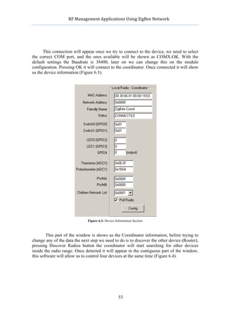
![RF
Management
Applications
Using
ZigBee
Network
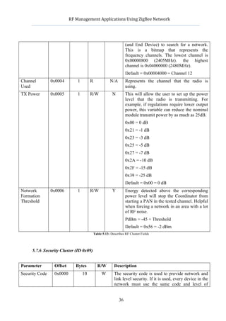
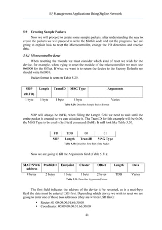
3 Introducing ZigBee Networks
3.1 What Does ZigBee Mean?
ZigBee is a new wireless communication protocol using small, low-power digital
radios based on the IEEE 802.15.4-2003 standard. This technology is considered to be
simpler and less expensive than other WPANs, such as Bluetooth. ZigBee is a good option
when considering a radio-frequency application that require a low data rate, long battery
life and secure networking [1].
This low-cost, low-power, wireless
mesh networking is a proprietary standard.
Very useful when using monitoring
applications, the low-power usage allows
devices to run for long time with small
batteries. Having a mesh type of network
provides the system with a high reliability
and larger range. This technology is
supported by the ZigBee Alliance that
publishes different profiles to be used by
multiple vendors to create interoperable
products. Multiple companies integrate the ZigBee Alliance: Philips, Schneider Electric,
Texas Instruments, Emerson, AT&T, Cisco, etc.
ZigBee is a very useful system to consider when designing Home Automation
systems that require very fast communication between all devices and the main computer.
This project will be focused in the Healthcare profile, which means it is designated to be
used in hospitals or similar.
3.2 Licensing
Luckily ZigBee specification is free for non-commercial uses, this kind of licensing
is very helpful when developing new applications for a new technology like ZigBee. This
part of the specification is controlled trough the ZigBee Alliance, an entry level
membership called Adopter gives permission to create products for market using the
specifications. This way of licensing also makes companies become friendly about this
new technology because if they don’t become part of the Alliance they will not be allowed
to use the specification for developing new products [2].
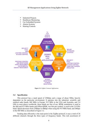
3.3 Uses
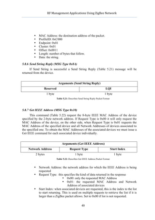
As said before, this protocol is focused in low-data transmission and long battery life.
Even this, applications are very common in our world, due to the low-cost of this
technology creating a wide network is not a problem. The resulting network will use very
small amounts of power so the cost gets even more reduced when talking about battery life.
Some typical areas of usage include (Figure 3.1):
• Home Entertainment
• Home Management
• Home Awareness
• Mobile Services
5](https://image.slidesharecdn.com/1492pub-120603092724-phpapp02/85/RF-Management-Applications-Using-ZigBee-Networks-5-320.jpg)
![RF
Management
Applications
Using
ZigBee
Network
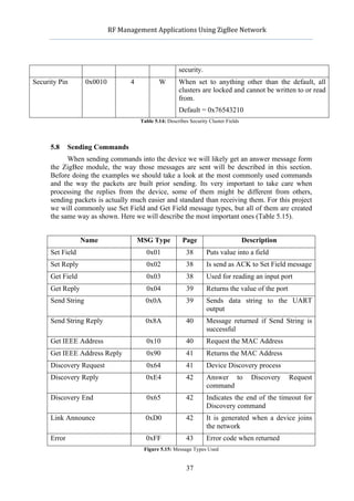
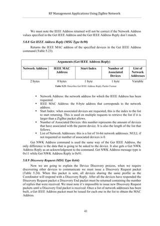
frequencies allows each device to be configured to work everywhere around the globe,
allowing companies to easily develop new applications. A ZigBee network can join up to
65000 devices.
Figure 3.2: IEE 802.15.4 Provides Three Frequency Bands
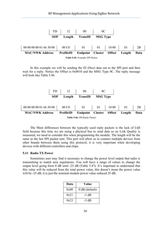
3.5 Battery Life
Usually when creating any RF application the problem related to the power
consumption relies to the radio. Sending data via any wireless system uses lots of energy;
this is something very important when talking about ZigBee. Those modules can activate
in 15ms or less, compared to any known wireless device such as Bluetooth, which takes
about three seconds to wake up, makes them be very fast responding to any command even
they are sleeping. Low latency results in power saving, saving power results in long battery
life.
Consider a typical temperature sensor, the sensor itself uses a clock at five seconds
interval to calculate the ambient temperature and send the event to the radio to be sent.
Analyzing any ZigBee module, it’s perfectly reliable to use the sleep system to save energy
while its not sending any data. This means any ZigBee module will work for months with
only one alkaline battery for sending data.
3.6 ZigBee Modulation
Those types of modulations are called Phase-Shift Keying; depending on the number
of bits it will be Quadrature (O-QPSK) with four bytes or Binary (BPSK). The main
difference between both of them is the number of points in the constellation diagram; those
modulations use a rectangular pulse [3].
The BPSK uses two phases which are separated 180º and can modulate one bit per
symbol, for this reason is unsuitable for high data-rate transmissions, even that, this
modulation is the most robust of all the PSK since it takes the highest level of noise or
distortion to make the demodulator reach an incorrect decision.
Offset-QPSK is a variant that uses 4 different values of the phase to transmit. Taking
four values of the phase at the same time to construct a QPSK symbol can allow the phase
of the signal to jump by as much as 180º at a time. When the signal is low-pass filtered,
7](https://image.slidesharecdn.com/1492pub-120603092724-phpapp02/85/RF-Management-Applications-Using-ZigBee-Networks-7-320.jpg)
![RF
Management
Applications
Using
ZigBee
Network
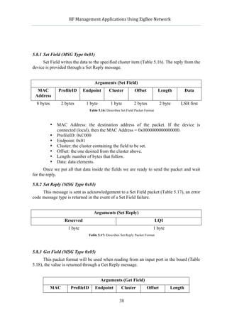
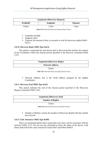
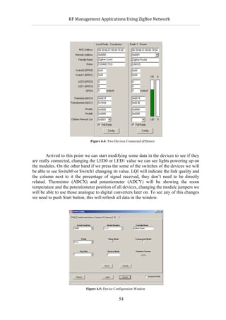
these phase-shifts result in large amplitude fluctuations, this is bad when talking about
communication systems. If we offset the timing of the odd and even by one or half symbol-
period, the components will never change at the same time, resulting in a much lower
amplitude fluctuations that makes it more difficult to make an incorrect decision (Figure
3.3).
Figure 3.3: Differences Between O-QSPK and QPSK
With four phases, this modulation can encode two bits per symbol, that means double
speed rate than a normal BPSK. That makes it reliable when trying to create faster transfer
communications systems.
3.7 Device Types
There are three different types of ZigBee devices: ZigBee Coordinator (ZC), ZigBee
Router (ZR) and ZigBee End Device (ZED). The Coordinator and Router are sometimes
referred to as Full Function Devices or FFDs. The End Device is sometimes called
Reduced Function Device or RFD [4].
3.7.1 ZigBee Coordinator
This is the main device of any ZigBee network; the coordinator forms the root of the
network three. There can be only one coordinator in each network, his work is to path the
communication of all devices and receive the necessary data to be processed. He is also in
charge of discovering new devices when needed and tracing them down in the network
route. If a Personal Area Network ID (Pan ID) has been specified the Routers and End
Devices will look for a Coordinator with the specified Pan ID, if the Coordinator has not
been found or it has a different Pan ID, they will automatically jump to the next channel on
its channel list until this Coordinator is found. The Coordinator will assign a 16-bit
network address to any new device that joins, this address is used to route the data inside
the network.
3.7.2 ZigBee Router
Router function is to pass data trough all devices on the network, this module can
work also as an End Device receiving data form sensors and running applications.
Actually, it is very similar to the Coordinator, it also acts the same way with the Pan ID but
it cannot distribute new addresses.
8](https://image.slidesharecdn.com/1492pub-120603092724-phpapp02/85/RF-Management-Applications-Using-ZigBee-Networks-8-320.jpg)
![RF
Management
Applications
Using
ZigBee
Network
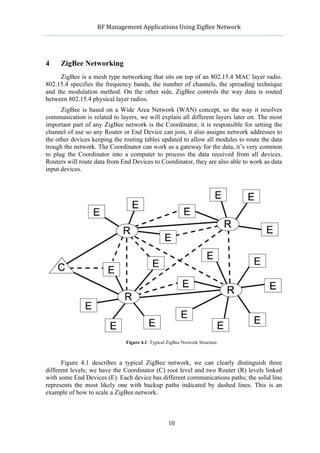
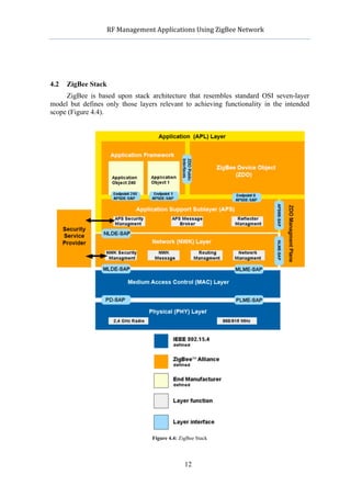
The ZigBee stack architecture is made up of a set of blocks called layers. Each layer
performs a specific set of services for the layer above. The IEEE 802.15.4 defines the two
lower layers, medium access control (MAC) and physical layer (PHY). The ZigBee
Alliance provides the Network (NWK) layer and the framework for the application layer,
which includes the Application Support (APS) sub-layer, the ZigBee device object (ZDO)
and the manufacturer-defined application objects [5].
IEEE 802.25.4 has two PHY layers that operate in two separate frequency ranges:
868/915 MHz and 2.4 GHz, depending on the country we will be using the device we will
switch between them. The MAC sub-layer controls access to the radio channel using
frames. The network layer provides mechanisms to join and leave network at the same
time as allows security and routing for the frames. The ZigBee application layer consists of
the APS sub-layer, the ZDO, and the manufacturer-defined application objects. The
responsibilities of the APS include maintaining tables for binding, which is the ability to
match two devices together based on their services and their needs, and forwarding
messages between bound devices. ZigBee Device Object (ZDO) defines the role of the
device within the network (coordinator, router or end device), discovering devices on the
network and determining which application services they provide, also relies on the
initiating and establishing secure relationship connection between network devices.
Zigbee stack is relatively small compared with other wireless standards; it only
requires about 32kb of memory for a full implementation of the stack.
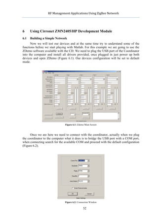
4.3 ZigBee Modules
For this project we will be operating with the Cirronet ZMN2405 ZigBee module but
there are other models and brands available in the market. In this part of the project we will
compare some kits and modules we can find in the market today. Lots of expensive kits of
about 2500$ are available on the market but those won’t be explained in here, we will just
compare the ones we consider similar to the Cirronet.
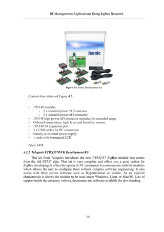
4.3.1 Jennic JN5148 Evaluation Kit
Probably this is one of the best options when considering which kit to buy for
development, but for our application the Cirronet kit fits better. Probably the Jennic kit
provides too many functions for what we were looking for. This kit can include up to 7
ZigBee modules (5 standard power and 2 high power modules), it also incorporates an
LCD screen and all needed software, this is one of the most complete kit available in the
market. Nodes come with pre-programmed software for demonstrating purposes. AT
commands are available for communicating with the devices [6]
13](https://image.slidesharecdn.com/1492pub-120603092724-phpapp02/85/RF-Management-Applications-Using-ZigBee-Networks-13-320.jpg)
![RF
Management
Applications
Using
ZigBee
Network
Figure 4.6: Telegesis Development Kit
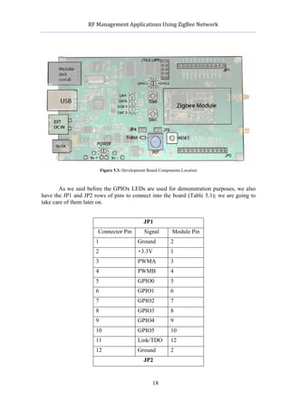
The kit contents and the module board connectors are well explained on the product
website [7] (Figure 4.6).
• 3 x USB Development Boards
• 2 x ETRX357 on Carrier-Board
• 2 x ETRX357HR on Carrier-Board
• 2 x ETRX357LR on Carrier-Board
• 2 x ETRX357HR-LR on Carrier-Board
• 1 x ETRX2USB stick
• 2 x Large Antenna
• 2 x Small Stubby Antenna
• 3 x USB Cable
Price: 348$ est.
15](https://image.slidesharecdn.com/1492pub-120603092724-phpapp02/85/RF-Management-Applications-Using-ZigBee-Networks-15-320.jpg)
![RF
Management
Applications
Using
ZigBee
Network
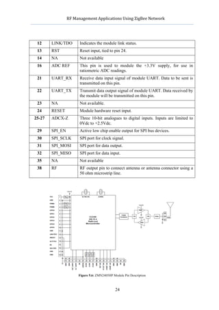
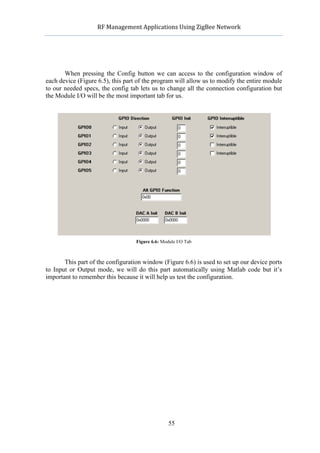
5 Cirronet ZMN2405/HP ZigBee Module
5.1 Specifications
For this project we had available a brand new ZMN2405/HP Cirronet ZigBee kit,
this kit contains everything needed to create a versatile and fast network. The contents of
the kit are (Figure 5.1):
• ZigBee Coordinator device.
• ZigBee Router device.
• Pair of dipole antennas.
• Pair of patch antennas.
• Two batteries.
• Two power adaptors.
• CD that includes software and manuals.
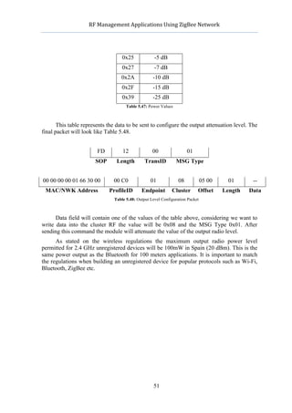
Figure 5.1: Kit ZMN2405/HP
We should distinguish the difference between the ZMN2405 and the ZMN2405/HP
model, the main difference between them is the output power, the first one provides about
1mW of RF power while the ZMN2405/HP provides 65mW. If we combine this module
with a 2dB dipole antenna we should be able to get 100mW in the case of ZMN2405/HP.
The one we are using in this project is the ZMN2405/HP; we will appreciate this point
when taking measurements of the LQI between the devices. This amount of output power
provides this kit with a high performance RF system that can be used trough very noisy
environments. The only problem with the ZMN2405/HP is related with the battery
consumption due to the high output power, so probably if we are interested on a limited
battery network we should consider using the ZMN2405 model [8].
16](https://image.slidesharecdn.com/1492pub-120603092724-phpapp02/85/RF-Management-Applications-Using-ZigBee-Networks-16-320.jpg)
![RF
Management
Applications
Using
ZigBee
Network
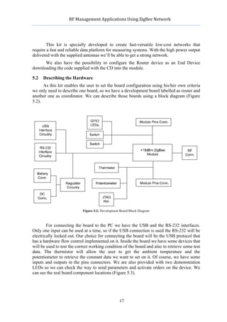
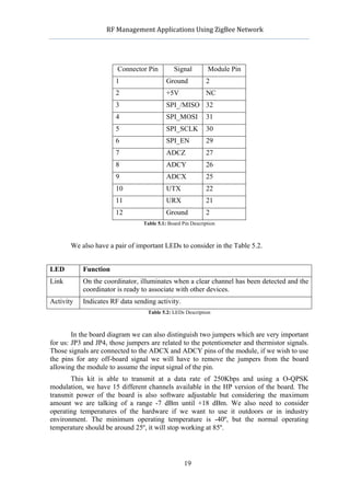
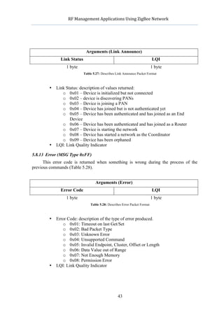
5.3 Texas Instruments CC2430
All signals on the ZMN2405HP module are directly connected to the input pins of
the CC2430. This chip is designed by Texas Instruments and the characteristics are
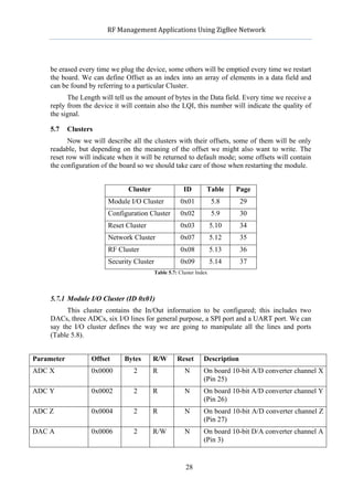
described in the Table 5.3 [10].
Flash/RAM 128kb/8kb
Frequency (Min) (MHz) 2400
Frequency (Max) (MHz) 2483.5
Operating Voltage (Min) 2V
Operating Voltage (Max) 3.6 V
Pin/Package 48VQFN
Operating Temperature Range (Celsius) 40 to 85
Device Type System-on-Chip
Frequency Range 2.4 GHz
Tx Power (dBm) 0
Rx Current (Lowest) (mA) 27
Sensitivity (Best) (dBm) -92
Wake Up Time (PD RX/TX) (uS) 645
Data Rate (Max) (Kbps) 250
Table 5.3: Describes Characteristics Of CC2430 Module
This CC2430 chip is available in three different versions CC2430F32/64/128, with
32/64/128 KB of flash memory respectively. This is a System-On-Chip (SoC) tailored for
the IEEE 802.14.5 that makes it perfect for ZigBee applications such as home monitoring,
industry, healthcare etc. it combines a 8050 MCU with the industry leading ZigBee
protocol stack (Z-Stack) from Texas Instruments. The price of this chip is between 3 – 6
USD; the CC2430 provides one of the market’s most competitive ZigBee SoC solutions.
5.3.1 RF/Layout
• 2.4 GHz IEEE 802.15.4 compliant RF transceiver (CC2430 radio core).
o 250 kbps data rate, 2 MChip/s chip rate.
o Reference designs comply with worldwide radio frequency
regulations covered by ETSI EN 300 328 and EN 300 440 class 2
(Europe), FCC CFR47 Part 25 (US) and ARIB STD-T66 (Japan).
Transmit on 2480MHz under FCC is supported by duty-cycling, or by
reducing output power.
• Excellent receiver sensitivity and robustness to interferers.
• Few external components, most parts are integrated into the chip.
20](https://image.slidesharecdn.com/1492pub-120603092724-phpapp02/85/RF-Management-Applications-Using-ZigBee-Networks-20-320.jpg)
![RF
Management
Applications
Using
ZigBee
Network
All this examples will be used later on together with the Matlab suite to connect our
device to the computer and be able to process data.
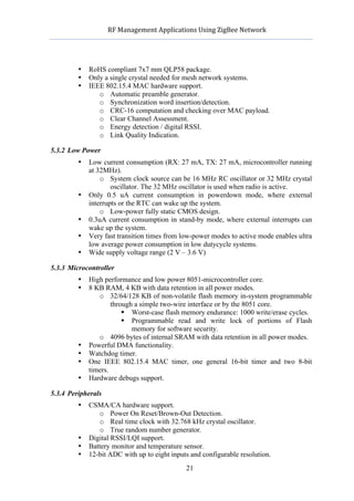
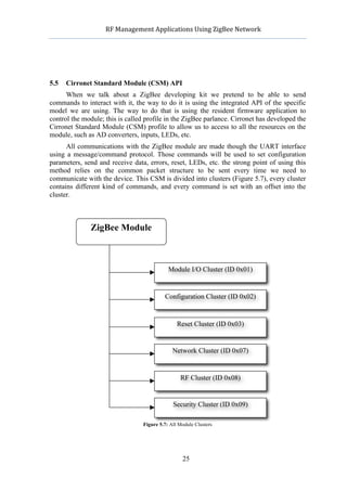
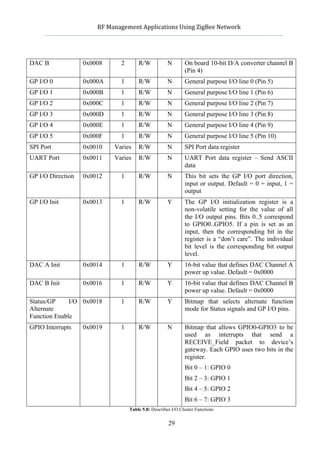
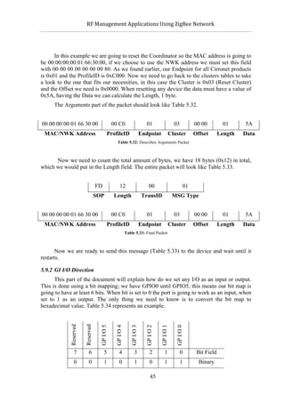
5.10 Using the SPI Bus
The Serial Peripherial Interface Bus is a full duplex bus standard created by Motorola
and communicates master/slave devices between them using three/four wires. In our
particular case it will be using four wires as shown in Table 5.44 [11].
Pin Name Description
29 SPI_EN Active low chip enable output for SPI bus devices
30 SPI_SCLK SPI port clock signal
31 SPI_MOSI SPI port data output
32 SPI_MISO SPI port data input
Table 5.44: Used Wires for SPI Communication
When beginning a communication the first transmitting device configures the clock
using a frequency less or equal than the destination device can support, commonly 1-70
MHz. During each SPI clock cycle a full duplex data transmission occurs, the master then
sends the bit in the SPI_MOSI meanwhile the slave reads the same line, then slave sends
the bit using the SPI_MISO and the master reads that line. Everything occurs at the same
time due a full duplex transmission (Figure 5.8). When transmission has finished master
device stops the clock and waits for new data to be sent or received.
Figure 5.8: Typical Transmission Using a Circular Buffer
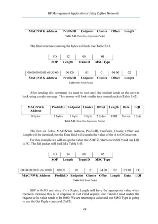
When sending data through the SPI ports in our Cirronet devices we need to activate
the SPI mode on the pin 29. When connecting both devices we only need to use the typical
sending commands and cluster modes to transmit using this protocol, described on Table
5.45.
49](https://image.slidesharecdn.com/1492pub-120603092724-phpapp02/85/RF-Management-Applications-Using-ZigBee-Networks-49-320.jpg)
![RF
Management
Applications
Using
ZigBee
Network
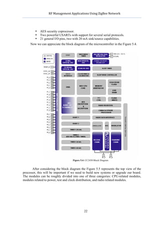
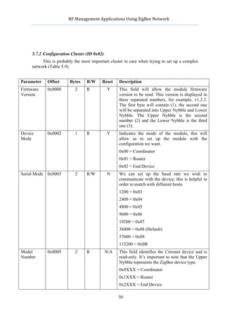
7 Matlab Libraries for ZigBee
In this part of the document we will expose the codes and functions we used during
the project with the examples and data acquired, see Table 7.1.
Function File Name Description Page
7.1 Socket Opening socket_openf() Opens socket to the ZigBee device 56
7.2 Bulding the Packet crear_cadena() Creates the chain to be sent 57
7.3 Reset Code resetf() Resets the module 57
7.4 Receiving/Sampling rebre_dada_final() Samples data from any A/D port 59
Data
7.4 Receiving/Sampling filtre_dades() Separates the data we need from 63
Data the received packet
7.5.1 LQI Test Function lqi_test() Tests the LQI value of a device 66
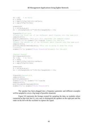
8.2.1 Sampling transformada() Calculates and plots the Fourier 79
Chirp transform of the captured
radar data
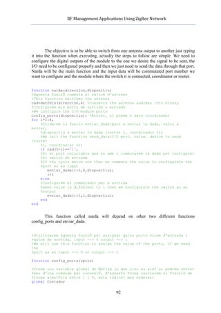
9 Antenna Array narda() Manages the antenna commutator 92
9 Antenna Array config_ports() Configures the I/O ports as desired 92
9 Antenna Array enviar_dada() Sends data into the I/O ports 93
Table 7.1: Function Table Index
7.1 Socket Opening (socket_openf)
The first code we need when using Matlab to communicate with the modules is a
socket opening function, we called it socket_openf.
%Function per obrir socket
%Function for socket opening
function s1=socket_openf(port)
%This function returns s1 with the open COM port information inside
%To call it: s1=socket_openf(COM PORT TO USE)
%We choose the port we want to use to connect the module
%Escollim el port que utilitzarem per connectar-nos al mÚdul ZigBee
DefaultSerialPort=['COM',num2str(port)]; %Port sel∑leccionat
s1 = serial( DefaultSerialPort, 'BaudRate', 38400); %115200,N,8,1 (la
resta esta per defecte)
fopen(s1); %Obrim la conexiÛ
%We ended oppenning the connection
end
56](https://image.slidesharecdn.com/1492pub-120603092724-phpapp02/85/RF-Management-Applications-Using-ZigBee-Networks-56-320.jpg)
![RF
Management
Applications
Using
ZigBee
Network
As we can see this is a simple code we will use every time we need to open a
connection port to the device.
7.2 Building the Packet (crear_cadena)
This function will be used also in all programs before sending the packet to the
device. We will need to build it.
function cad =
crear_cadena(resta,Address,ProfileID,Endpoint,Cluster,Offset,Len,Data,Tim
eout)
%Description:
%This function will return the cad vector
%resta:SOP+Length+TransID+MSG Type
%The rest of the data corresponds to the ZigBee packet nomenclature
%Creem la cadena amb les dades entrades
%We build the chain with the input data
Comando=[resta,Address,ProfileID,Endpoint,Cluster,Offset,Len,Data,Timeout
]; %Ho posem tot en una variable ˙nica / Everything together in a single
vector
cad=[]; %Creem un vector per a desar-ho un cop passat a Hex /We will save
the chain in Hex mode
for i=1:2:length(Comando), %Bucle fins el final de la comanda a canviar
%Passem a Hex totes les dades i ho anem encadenant
%We convert to Hex all data in the chain at the same time as we save
it
%into cad []
cad=[cad,(hex2dec(Comando(i:(i+1))))];
end
end
That code will help us to pack all the message we want to send into a vector called
cad[], this vector will be returned to the main program so it can be processed to the device.
7.3 Reset Code (resetf)
This code created with Matlab is used to remotely reset the device. First of all let’s
show the code:
function resetf(opcio)
%Example:
%resetf(1) this will reset the Router
%resetf(2) this will reset the Coordinator
%No data is returned in this function
%Triem si resetegem el router o el coordinador
%We choose wich device we want to reset
57](https://image.slidesharecdn.com/1492pub-120603092724-phpapp02/85/RF-Management-Applications-Using-ZigBee-Networks-57-320.jpg)
![RF
Management
Applications
Using
ZigBee
Network
if opcio==1,
%Router
Address='0100000001663000';
end
if opcio==2,
%Coordinador
Address='0000000001663000';
end
%We create a global variable for the TransID problem, we need to change
the
%TransID in each command we send, so we can switch between 00 and 01
global Contador
if isempty(Contador),
Contador=0;
end;
TransID=dec2hex(Contador,2);
Contador=1-Contador;
%Codi a enviar
%Packet to be built
SOP='FD';
length='11';
MSGType='01';
resta=[SOP,length,TransID,MSGType];
ProfileID='00C0';
Endpoint='01';
Cluster='03';
Offset='0000';
Len='01';
Data='5A';
Timeout='';
%Cridem obertura del socket al port COM3
%Open the COM3 socket using socket_openf
s1=socket_openf(3);
%Creem la cadena de la comanda a enviar
%We build the packet to be sent
cad=crear_cadena(resta,Address,ProfileID,Endpoint,Cluster,Offset,Len,Data
,Timeout);
%Enviem la comanda
%We send the packet
fwrite(s1,cad);
%Close socket
fclose(s1);
end
When this code is executed the device will reset. It’s very useful to combine this
function with other programs in the desired way, some times we might want to reset the
device to default, changing the Data field will reset the device with factory defaults.
58](https://image.slidesharecdn.com/1492pub-120603092724-phpapp02/85/RF-Management-Applications-Using-ZigBee-Networks-58-320.jpg)
![RF
Management
Applications
Using
ZigBee
Network
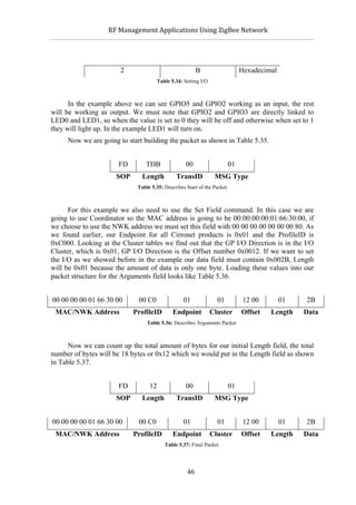
7.4 Receiving / Sampling Data (rebre_dada_final)
For this project we will be using this code to sample input data in the analogue ports
ADCX, ADCY and ADCZ. This code will save all the samples we desire to get to a matlab
file so we can load it later and plot them if necessary.
function rebre_dada_final(opcio,ports,canal1,canal2,canal3,mostres)
%This function will be used to sample analogue data from any ADCx ports
%All data will be save into mesura.mat
%Opcio: 1 Router, 2 Coordinator
%Ports: Desired COM port
%Canal1: Will sample from ADCX if 1 is set, desactivated if 0
%Canal2: Will sample from ADCY if 1 is set, desactivated if 0
%Canal3: Will sample from ADCZ if 1 is set, desactivated if 0
%Mostres: The amount of samples we desire
%mesura1 mesura2 mesura3 t3 t2 t1 t_pot potencia data will be saved
%Creem una variable global de Matlab ja que sino es aixÌ no podrem enviar
%mes d'una comanda per connexiÛ, d'aquesta forma canviarem el TransID de
%forma aleatÚria entre 1 i 0, esta indicat mes endevant
%We create a global variable for the TransID problem, we need to change
the
%TransID in each command we send, so we can switch between 00 and 01
global Contador
if isempty(Contador),
Contador=0;
end;
%Script variables used
%Variables del script
n=0;
index=1;
canal1=10;
canal2=10;
canal3=10;
mesura1=[];
mesura2=[];
mesura3=[];
t1=[];
t2=[];
t3=[];
%If no input data is made then we will ask for it
if nargin==0,
%Entrada de la selecciÛ del dispositiu amb control d'errors
%Wich device we want data to be sampled from
while (n==0)
opcio=input('De quin dispositiu vols rebre les dades?(1=Router,
2=Coordinador) ');
if (opcio~=1)&&(opcio~=2),
disp('OpciÛ incorrecte, torna-ho a provar');
n=0;
else
n=1;
end
end
59](https://image.slidesharecdn.com/1492pub-120603092724-phpapp02/85/RF-Management-Applications-Using-ZigBee-Networks-59-320.jpg)
![RF
Management
Applications
Using
ZigBee
Network
length='11';
ProfileID='00C0';
Endpoint='01';
Cluster='01';
Len='02';
Data='';
Timeout='';
MSGType='05';
%Varible que correspon al temps inicial, per poder realitzar c‡lculs
%temporals
%We will use this variable to calculate times between packets and
similar,
%it's only a initial clock
t0=clock;
%Receiving data
%Bucle per rebre les dades
while(index<=mostres+1)
%If the channel has been selected previously we retreive data from it
if canal1==1 ,
%Offset del canal que cal enviar
%Offset of the channel
Offset='0000';%ADC0 o ADCX
%Aquesta comanda s'utilitza per a poder canviar el TransID i
d'aquesta
%forma poder enviar mÈs d'una comanda per connexiÛ i no fer-ho
manualment
%We will use this command to change the TransID every time we
need
%to retreive the data, even if its from different channels
TransID=dec2hex(Contador,2);
Contador=1-Contador;
%Creem la primera part de la cadena del paquet ZigBee
%Beggining of the ZigBee packet
resta=[SOP,length,TransID,MSGType];
%Cridem a la funciÛ per crear la cadena de car‡cters que ens la
retorna en
%Hex
%We call crear_cadena to build the vector with the data to be
sent
cad=crear_cadena(resta,Address,ProfileID,Endpoint,Cluster,Offset,Len,Data
,Timeout);
%Enviem la comanda al dispositiu
%Sending data
fwrite(s1,cad);
%Rebem el paquet i filtrem les dades que nosaltres volem, nomÈs
utilitzarem
%la potÈncia i LQI (per a proves de senyal)
%Once data has been sent then we retreive the response packet
61](https://image.slidesharecdn.com/1492pub-120603092724-phpapp02/85/RF-Management-Applications-Using-ZigBee-Networks-61-320.jpg)
![RF
Management
Applications
Using
ZigBee
Network
from
%the device wich contains the sample we want to save together
with
%the LQI
%We call filtre_dades to filter the data we are interested in
[LQI,ADCZ] = filtre_dades(s1);
mesura1(index)=ADCZ; %Save the sample into the vector mesura1()
%Save the LQI into the vector potencia(), this vector will be
%common in all channels to keep all the LQI from the received
%packets together
potencia(index+n)=LQI;
%Temps utilitzat per fer la gr‡fica del LQI si es requereix
%Total time used to receive the packet, we will need that in
order
%to plot LQI
t_pot(index+n)=etime(clock,t0);
%Contador per guardar el LQI i el t_pot en una taula acumulativa
%Counter to accumulate for the LQI and t_pot vector
n=n+1;
%Time of the data from the first channel
t1(index)=etime(clock,t0);
end
if canal2==1 ,
Offset='0200';%ADC0 o ADCY
TransID=dec2hex(Contador,2);
Contador=1-Contador;
resta=[SOP,length,TransID,MSGType];
cad=crear_cadena(resta,Address,ProfileID,Endpoint,Cluster,Offset,Len,Data
,Timeout);
fwrite(s1,cad);
[LQI,ADCZ] = filtre_dades(s1);
mesura2(index)=ADCZ;
potencia(index+n)=LQI;
t_pot(index+n)=etime(clock,t0);
n=n+1;
t2(index)=etime(clock,t0);
end
if canal3==1 ,
Offset='0400';%ADC3 o ADCZ
TransID=dec2hex(Contador,2);
Contador=1-Contador;
resta=[SOP,length,TransID,MSGType];
cad=crear_cadena(resta,Address,ProfileID,Endpoint,Cluster,Offset,Len,Data
,Timeout);
fwrite(s1,cad);
[LQI,ADCZ] = filtre_dades(s1);
62](https://image.slidesharecdn.com/1492pub-120603092724-phpapp02/85/RF-Management-Applications-Using-ZigBee-Networks-62-320.jpg)
![RF
Management
Applications
Using
ZigBee
Network
mesura3(index)=ADCZ;
potencia(index+n)=LQI;
t_pot(index+n)=etime(clock,t0);
n=n+1;
t3(index)=etime(clock,t0);
end
n=0;
index=index+1;
end
%We save all vectors into mesura.mat, we can rename and load it later if
%needed
save mesura.mat mesura1 mesura2 mesura3 t3 t2 t1 t_pot potencia
disp('Finalitzat OK!');
plot(t_pot,potencia)
xlabel('t(s)'); ylabel('LQI');grid;
%Closing COM connection
%Tanquem la connexiÛ un cop acabat el procÈs
fclose(s1);
After this process we can load the mesura.mat in order to plot the samples. Shown
function also calls filtre_dades code. We created this function to separate all the useful data
in the answer packet and discard all unneeded bytes.
function [LQI,ADCZ] = filtre_dades(s1)
%This function filters the data we need from the rest of the packet
%Returns LQI and ADCZ vectors which include the data and the LQI
%s1 contains the socket we opened previously using socket_openf()
%Reading the reply from the device and filtering
cad=fread(s1,2);
N=cad(2);
cad=fread(s1,N);
Ndata=cad(17);
ValorData=cad(18:(18+Ndata-1));
LQI=cad(end);
ADCZ=ValorData(2)*256+ValorData(1);
end
Once reached this point we are ready to test the connection with the device and try
to sample something.
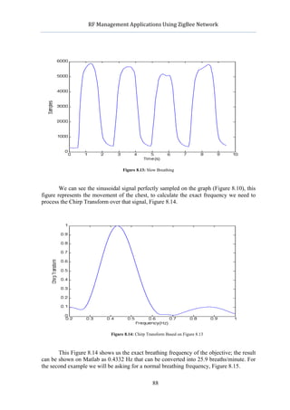
7.4.1 Sampling Examples
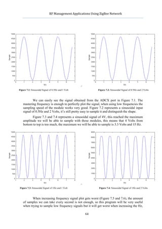
The first signal we tried to sample was a continuous sinusoidal signal created from a
generator, this helped us to discover the amount of volts and frequency the device and be
able to sample. This was the first time we really tried the ADCx device inputs.
63](https://image.slidesharecdn.com/1492pub-120603092724-phpapp02/85/RF-Management-Applications-Using-ZigBee-Networks-63-320.jpg)
![RF
Management
Applications
Using
ZigBee
Network
index=1;
%Init variable for the first loop
teclat=1;
interval=input('Cada cuants metres voleu pendre una mostra ?');
disp('Camineu la distancia introduÔda aproximadament i apreteu 1, cuan
hagueu finalitzat apreteu 2')
while (teclat==1)
%This function waits for a keypress
teclat=input('Premeu 1 seguit de ENTER per continuar: ');
if teclat == 1
%We control the TransID field
TransID=dec2hex(Contador,2);
Contador=1-Contador;
%Increase the meters
contador_metres=contador_metres+interval;
%Show the meter we are taking sample
contador_metres
%Builds the packet to be sent
resta=[SOP,length,TransID,MSGType];
cad=crear_cadena(resta,Address,ProfileID,Endpoint,Cluster,Offset,Len,Data
,Timeout);
%Sending data
fwrite(s1,cad);
%Receives the LQI value from filtre_dades() function
[LQI,ADCZ] = filtre_dades(s1);
%Saves the value of the A/D field into a vector
MESURA(index)=ADCZ;
LQI %Shows LQI value in screen
LQI_MESURA(index)=LQI; %Saves the LQI value
%Increases the reference points for the vectors
CONTADOR_MESURA(index)=contador_metres;
index=index+1;
end
end
fclose(s1);
%This part will plot the LQI signal received
plot(CONTADOR_MESURA,LQI_MESURA);
xlabel('Metres'); ylabel('LQI');grid; %Labels for the plot and grid
%Saves the LQI information into a file
save mesura.mat LQI_MESURA CONTADOR_MESURA
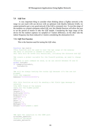
7.5.2 Tests
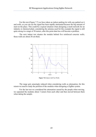
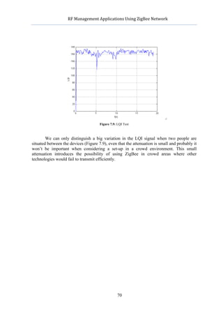
Our first try has been in a big open air parking lot, in this case the distance between
the devices without data lost has been amazing, we could easily reach 150 meters or maybe
200 meters with a good link quality.
67](https://image.slidesharecdn.com/1492pub-120603092724-phpapp02/85/RF-Management-Applications-Using-ZigBee-Networks-67-320.jpg)
![RF
Management
Applications
Using
ZigBee
Network
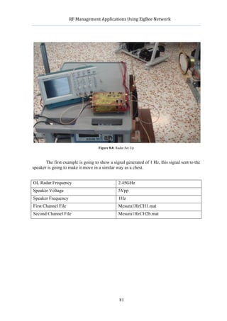
8 Radar Sampling
The main purpose for this project is to find a practical application for ZigBee transfer
technology; this part of the project is going to describe a practical situation where we can
apply this protocol to get a faster and easier transfer method. In our case we will be using
radar to control human vital signals through the computer. During the last years lots of
different methods have been developed for human monitoring but all of them have
intrusive consequences, now it’s possible to create a signals monitoring system that doesn’t
need to be attached to the patient’s body.
This system has many applications in real life, you can plug any radar to the ZigBee
module making it flexible when transmitting through a building or open area. It may help
to monitor people in hospitals, control non-born babies or ambulances and maybe find
people underground in some earthquakes extreme situations. Those are only some of the
applications you can find plugging this type of radar into a ZigBee module.
8.1 Theory
For this project we are using a Doppler radar that transmits a pure sinusoidal signal
similar to cos2πft ; this signal will be reflected by the objective and then returned to the
radar for demodulation process. Considering the Doppler theory a static object that varies
his position in time but has no movement will reflect the signal with a proportional phase
modulation of the position related to time. If we consider a person sitting on a chair with
his chest moving, this chest will have a periodic movement that can be reflected with the
€
desired radar signal. When pointing the signal sent to the chest this will return a similar
signal but modified with the variation of the chest movement. This will be proportional to
time; once this signal is demodulated on the radar we will directly get the heart/breath rate
of that person proportional to time [12].
When analysing the input signal first we need to focus in the output signal:
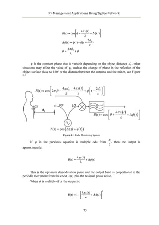
T(t) = cos(2πft + φ (t))
φ (t) Represents the phase. If the signal is reflected by an objective situated at d0
with a variation of time x(t), the total distance until it comes back to the radar will be
€
2d(t) = 2d0 + 2x(t) . Received wave will look like this:
€
€
71](https://image.slidesharecdn.com/1492pub-120603092724-phpapp02/85/RF-Management-Applications-Using-ZigBee-Networks-71-320.jpg)
![RF
Management
Applications
Using
ZigBee
Network
x(t) = x(t − ψ (t))
2d(t − t 0 )
ψ (t) =
c
2d(t − t 0 ) 2d(t − t 0 )
R(t) = cos[2πf (t − ) + φ (t − )]
c c
e d(t)
t0 = =
v c
d(t) d(t)
2d(t − ) 2d(t − )
R(t) = cos[2πf (t − c ) + φ (t − c )]
c c
c
Finally we need to apply
€ 2d(t) = 2d0 + 2x(t) and λ = .
f
⎡ ⎛ d(t) ⎞ ⎛ ⎛ d(t) ⎞ ⎞ ⎤
€ ⎢ 4 πx⎜ t − € ⎟ ⎜ 2x⎜ t − ⎟ ⎟ ⎥
R(t) = cos ⎢2πft − 4 πd0 − ⎝ c ⎠ ⎜ 2d0
+φ t − −
⎝ c ⎠ ⎟ ⎥
⎢ λ λ ⎜ c c ⎟ ⎥
⎢ ⎜ ⎟ ⎥
⎣ ⎝ ⎠ ⎦
d(t) ⎛ d(t) ⎞
€ Assuming that is negligible in x⎜ t − ⎟ because the chest moves with a
c ⎝ c ⎠
⎛ d(t) ⎞
x⎜ t − ⎟
d(t) ⎝ c ⎠
period T >> , and is negligible in the φ term, we can approximate
€c c
received signal as: €
€ € ⎡ 4 πd0 € πx(t) ⎛ 2d0 ⎞ ⎤
4
R(t) = cos⎢2πft − − + φ⎜ t − ⎟ ⎥
⎣ λ λ ⎝ c ⎠ ⎦
Received signal is similar to the transmitted but retarded in time determined by the
distance to the object and with his phase modulated by the periodic movement from the
€
object. We need to get the information from the distance that the object has moved, to get
this data we need to demodulate the signal with an OL that is provided from the same
origin as the transmitted signal. When the received signal and the OL are mixed together
and sent through a low-pass filter the equation we get is this one:
72](https://image.slidesharecdn.com/1492pub-120603092724-phpapp02/85/RF-Management-Applications-Using-ZigBee-Networks-72-320.jpg)
![RF
Management
Applications
Using
ZigBee
Network
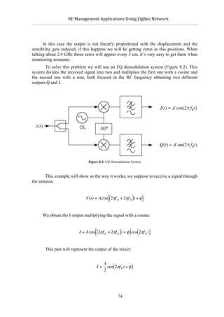
Once simplified the result is very easy to plot, then the Q output is obtained
multiplying with a sine:
(( ) ) (
Q = Acos 2πf rf + 2πf D t + φ sin 2πf rf t )
A
Q=− cos(2πf D t + φ )
2
Using this demodulation system we are avoiding all the zeros obtaining two different
€ π
channels Q and I with a phase displacement of . If one output has a zero the other one
2
won’t. In the receiver both channels will be calculated as:
€ π 4 πx(t)
⎡ ⎤
BQ (t) = cos⎢θ − + + Δφ (t) ⎥
⎣ 4 λ ⎦
⎡ π 4 πx(t) ⎤
BI (t) = cos⎢θ + + + Δφ (t) ⎥
⎣ 4 λ ⎦
Using any of both components we will be able to obtain breath rate applying the
€
Fourier Chirp transform [13].
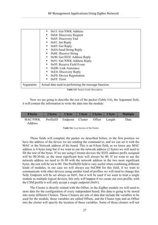
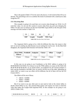
8.2 Radar Sampling Using ZigBee Network
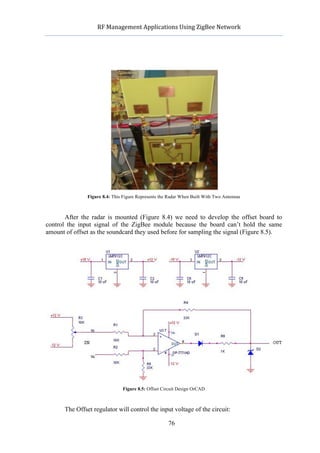
The design created for the radar with the ADS is shown in Figure 8.3.
Figure 8.3: Radar Design Using ADS
We have two amplifiers to receive the signal and one to transmit; the right part of
the schematic represents the IQ demodulator.
75](https://image.slidesharecdn.com/1492pub-120603092724-phpapp02/85/RF-Management-Applications-Using-ZigBee-Networks-75-320.jpg)
![RF
Management
Applications
Using
ZigBee
Network
if isempty(Contador),
Contador=0;
end;
if opcio==1,
%Router
Address='0100000001663000';
end
if opcio==2,
%Coordinador
Address='0000000001663000';
end
%Dades per a crear el packet ZigBee
%ZigBee packet
SOP='FD';
length='12';
TransID=dec2hex(Contador,2);
Contador=1-Contador;
MSGType='01';
%Creem la primera part de la cadena del paquet ZigBee
%First part of the ZigBee chain
resta=[SOP,length,TransID,MSGType];
ProfileID='00C0';
Endpoint='01';
Cluster='01';
Offset='1200';
Len='01';
Timeout='';
%Configurarem els ports del GPIO0 al GPIO5 amb els bits 0 i 1, cuan sigui
0
%estaran configurats d'entrada i cuan sigui 1 de sortida
%This part is where the ports are configured, if we want them to be
%configured as an ouput then we set them as 1 otherwise they will be 0
%GPIO5...GPIO0 --> 00111111
Data=dec2hex(bin2dec('00111111'),2)
%Port de connexio COM3 en el nostre cas
%Cridem obertura del socket
%We open the COM3 socket for sending the order
s1=socket_openf(3);
%Creem la cadena de la comanda a enviar
%Create the packet to be sent
cad=crear_cadena(resta,Address,ProfileID,Endpoint,Cluster,Offset,Len,Data
,Timeout);
%Enviem la comanda
%Send command
fwrite(s1,cad);
fclose(s1);
function enviar_dada(gpio,valor,opcio)
%Creem una variable global de Matlab ja que sino es aixÌ no podrem enviar
%mes d'una comanda per connexiÛ, d'aquesta forma canviarem el TransID de
%forma aleatÚria entre 1 i 0, esta indicat mes endevant
global Contador
93](https://image.slidesharecdn.com/1492pub-120603092724-phpapp02/85/RF-Management-Applications-Using-ZigBee-Networks-93-320.jpg)
![RF
Management
Applications
Using
ZigBee
Network
if isempty(Contador),
Contador=0;
end;
n=0;
%La variable opciÛ tria a quin dispositiu enviarem la comanda
if opcio==1,
%Router
Address='0100000001663000';
end
if opcio==2,
%Coordinador
Address='0000000001663000';
end
%Dades per a crear el packet ZigBee
%ZigBee packet
SOP='FD';
length='12';
TransID=dec2hex(Contador,2);
Contador=1-Contador;
MSGType='01';
%Creem la primera part de la cadena del paquet ZigBee
%First part of the ZigBee chain
resta=[SOP,length,TransID,MSGType];
ProfileID='00C0';
Endpoint='01';
Cluster='01';
Len='01';
Timeout='';
%Depenent del GPIO que entri per els arguments enviarem la dada per un
GPIO
%o unaltre, aquest valor vÈ donat per la funciÛ narda
%The GPIO we select in the input arguments will be the one to send the
data
%into
if (gpio == 0)
Offset='0A00';
end
if (gpio == 1)
Offset='0B00';
end
if (gpio == 2)
Offset='0C00';
end
if (gpio == 3)
Offset='0D00';
end
if (gpio == 4)
Offset='0E00';
end
if (gpio == 5)
Offset='0F00';
end
Data=dec2hex(valor,2);
%Cridem obertura del socket
94](https://image.slidesharecdn.com/1492pub-120603092724-phpapp02/85/RF-Management-Applications-Using-ZigBee-Networks-94-320.jpg)
![RF
Management
Applications
Using
ZigBee
Network
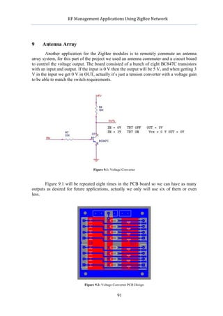
The reason of creating this antenna switch management is the aim to develop a new
system for breast cancer detection, for this purpose it will be using different antennas to
detect the cancer. Using microwaves coming from different antennas and managing to
receive the data sample at high speed it could be possible to create an image from the
tumour in a screen as is done now with traditional breast detection systems. This picture
will be plotted using tomography [13], this method is based on drawing through sections a
full picture, a similar way it’s used for radiology. [14][15][16]
96](https://image.slidesharecdn.com/1492pub-120603092724-phpapp02/85/RF-Management-Applications-Using-ZigBee-Networks-96-320.jpg)
![RF
Management
Applications
Using
ZigBee
Network
12 References
[1] ZigBee Wikipedia (ES)
http://es.wikipedia.org/wiki/ZigBee
[2] ZigBee Alliance
http://www.zigbee.org/
[3] Phase-shift Keying Wikipedia (EN)
http://en.wikipedia.org/wiki/Phase-shift_keying
[4] ZigBee Meshnetics
http://www.meshnetics.com/zigbee-faq/
[5] ZigBee Protocol Wikipedia (EN)
http://en.wikipedia.org/wiki/ZigBee_specification
[6] Jennic JN5148
http://www.jennic.com/products/development_kits/jn5148_evaluation_kit
[7] Telegesis ETRX357DVK
http://www.telegesis.com/ETRX3-development-Kit.htm
[8] Cirronet ZMN2405/HP
http://www.rfm.com/products/data/zmn2405hpdk.pdf
[9] ZMN2405HP Manual
http://www.rfm.com/products/data/zmn2405_manual.pdf
[10] Texas Instruments CC2430 Datasheet
http://focus.ti.com/general/docs/lit/getliterature.tsp?genericPartNumber=cc2430&fileType
=pdf
[11] Serial Peripherial Interface Bus Wikipedia (EN)
http://en.wikipedia.org/wiki/Serial_Peripheral_Interface_Bus
[12] W. Massagram, N. Hafner, B. Park, V. Lubecke, A. Madsen, O. Lubecke, “Feasibility
of Heart Rate Variability Measurement from Quadrature Doppler Radar Using Arctangent
Demodulation with DC Offset Compensation” in IEEE Conference, August 2007
http://www.ncbi.nlm.nih.gov/pubmed/18002288
[13] Rabiner, L.R., and B. Gold. Theory and Application of Digital Signal Processing,
Englewood Cliffs, NJ: Prentice-Hall, 1975.
[14] Fear, E.C., P. M. Meaney, and M. A. Stuchly, “Microwaves for breast cancer
detection?,” /IEEE Potentials/, Vol. 22, No. 1, 12–18, 2003.
99](https://image.slidesharecdn.com/1492pub-120603092724-phpapp02/85/RF-Management-Applications-Using-ZigBee-Networks-99-320.jpg)
![RF
Management
Applications
Using
ZigBee
Network
[15] Fear, E.C., J. Sill and M.A. Stuchly, “Experimental Feasibility Study of Confocal
Microwave Imaging for Breast Tumor Detection,” /IEEE Trans. Microwave Theory Tech./,
Vol. 51, No. 3, 887-892, 2003.
[16] Bindu, G., A. Lonappan, V. Thomas, C. K. Aanandan, and K. T. Mathew, “Active
microwave imaging for breast cancer detection”, /Progress In Electromagnetics Research/,
PIER 58, 149–169, 2006.
100](https://image.slidesharecdn.com/1492pub-120603092724-phpapp02/85/RF-Management-Applications-Using-ZigBee-Networks-100-320.jpg)

The document focuses on RF management applications using Zigbee networks, highlighting the technology's low power consumption and cost-effectiveness for various applications, particularly in healthcare and industrial monitoring. It provides a detailed overview of the Zigbee protocol, including its specifications, device types, and networking capabilities. The project aims to demonstrate the potential of Zigbee technology in enhancing communication and monitoring in medical and industrial sectors.


![Zigbee technology [autosaved]](https://cdn.slidesharecdn.com/ss_thumbnails/zigbeetechnologyautosaved-140716030459-phpapp02-thumbnail.jpg?width=640&height=640&fit=bounds)


