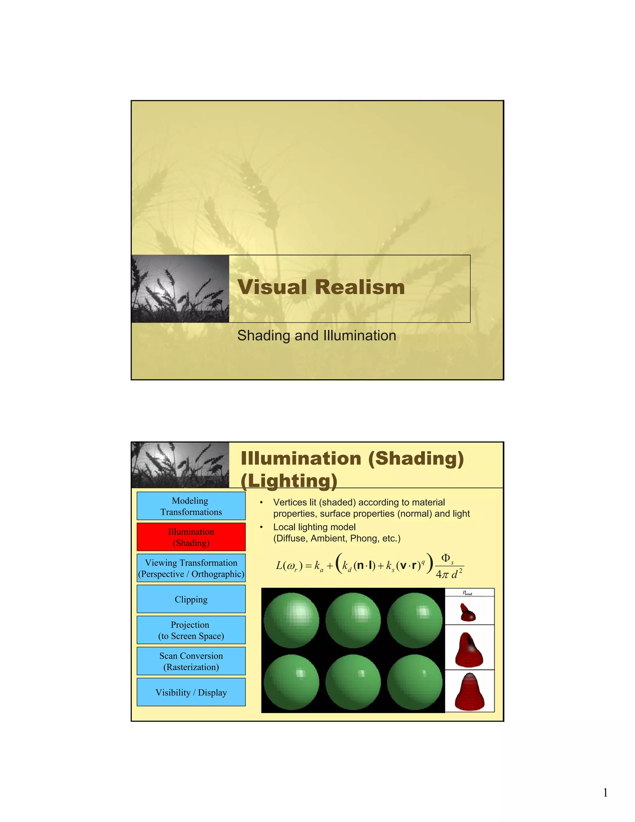
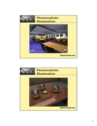
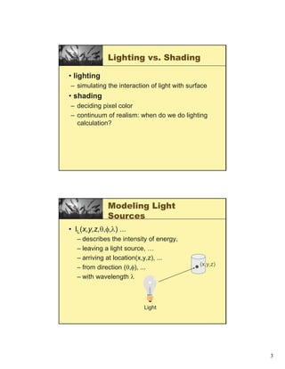
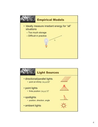
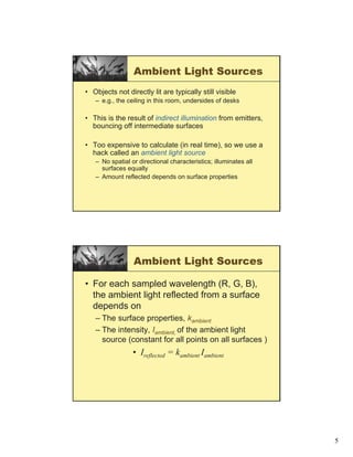
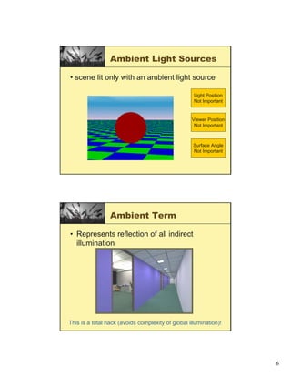
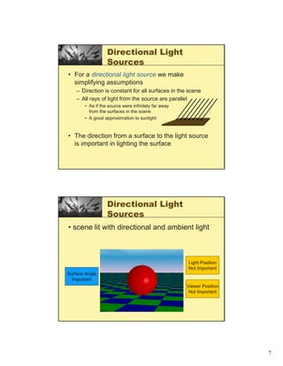
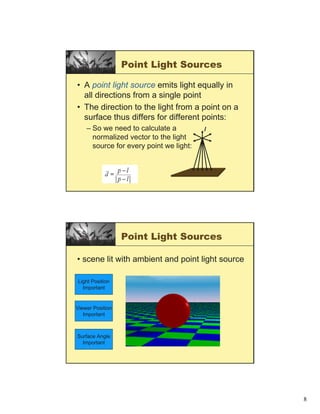
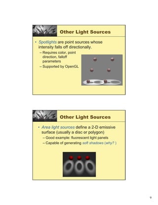
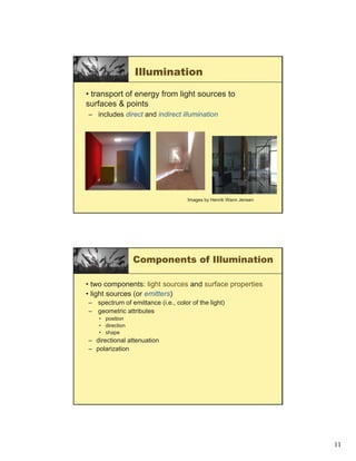
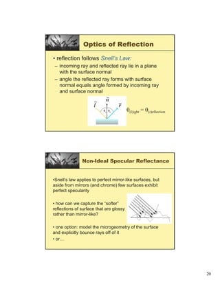
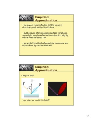
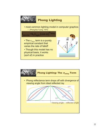
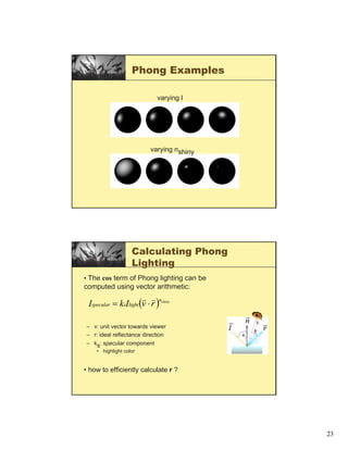
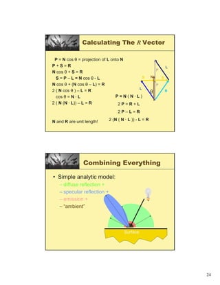
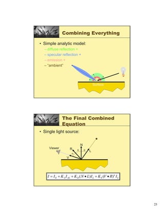
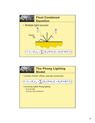
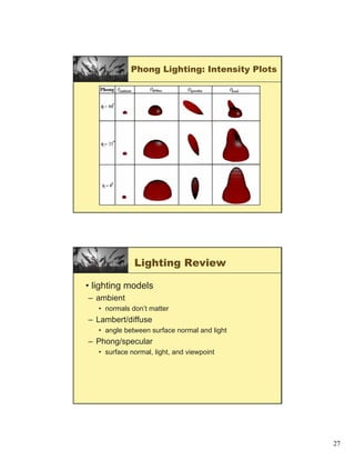
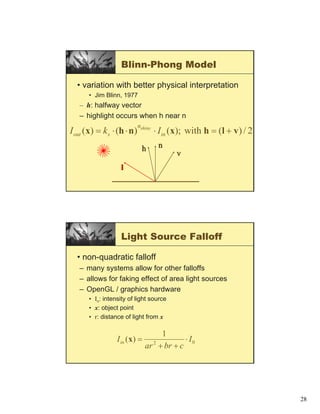
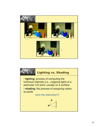
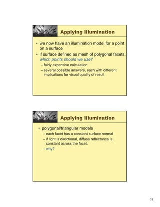
This document discusses concepts related to visual realism in computer graphics such as illumination, shading, lighting models, and surface reflectance. It provides information on different types of lights including ambient, directional, point lights and spotlights. It also covers surface reflectance models including diffuse, specular, and the Phong and Blinn-Phong lighting models which combine elements of ambient, diffuse and specular reflection. Key concepts discussed include Lambert's cosine law, Fresnel equations, and the use of vectors and angles to calculate diffuse and specular reflection.
illumination model in Computer Graphics by irru pychukarsyedArr
The document discusses illumination models used to calculate light intensity on object surfaces in 3D scenes. It describes how surface rendering uses illumination models to determine pixel intensities. Diffuse and specular reflection are explained along with parameters like ambient light, material properties, number of light sources, attenuation, and shadows. Color considerations and transparent surfaces are also covered at a high level.
Cs8092 computer graphics and multimedia unit 1SIMONTHOMAS S
This document discusses illumination models and color models in computer graphics. It begins by introducing illumination models which determine the perceived color and intensity at points on a surface given lighting conditions. It then covers various lighting models including point light sources, damping of light intensity over distance, and the Phong illumination model for specular reflection. It also discusses surface illumination factors like reflection, transmission and absorption of light. Basic illumination models are presented combining ambient, diffuse and specular reflection. The document concludes by covering rendering of polygons using constant, Gouraud and Phong shading to interpolate colors across surfaces.
The document describes the Phong shading model for modeling specular reflections. It explains that specular reflection results from total or near-total reflection of incident light in a concentrated region around the specular reflection angle. The Phong model sets the intensity of specular reflection proportional to the cosine of the viewing angle raised to a power 'n'. Higher values of 'n' produce shinier surfaces, while lower values produce duller surfaces. The model calculates specular reflection based on vectors representing the light source, viewer, and specular reflection direction.
This document discusses various lighting and shading techniques used in computer graphics, including:
- Ray tracing and radiosity methods that aim to approximate physical light behavior more accurately but with higher computational cost.
- Phong illumination model that provides relatively fast approximations of light interactions.
- Calculation of diffuse and specular reflection components in the Phong model based on surface normals, light direction, and view direction.
- Different shading techniques like flat, Gouraud, and Phong shading that determine color values at polygon vertices and faces.
The document discusses concepts related to basic illumination models. It covers key components like ambient light, diffuse illumination, and specular reflection that contribute to how objects are illuminated. It notes that illumination models try to approximate real world lighting in a realistic but not perfectly accurate way. The document also discusses challenges like accounting for all light rays reflected between nearby objects and having multiple light sources and viewing directions in a scene.
The document discusses various illumination models used in computer graphics including ambient light, point light sources, distributed light sources, Beer Lambert's law, chromaticity diagrams, flat shading, Gouraud shading, the Phong illumination model, and the Ward illumination model. It provides details on how each model calculates light intensity and color values for surfaces and polygons in a 3D scene.
An illumination model, also called a lighting model and sometimes referred to as a shading model, is used to calculate the intensity of light that we should see at a given point on the surface of an object.
Surface rendering means a procedure for applying a lighting model to obtain pixel intensities for all the projected surface positions in a scene.
A surface-rendering algorithm uses the intensity calculations from an illumination model to determine the light intensity for all projected pixel positions for the various surfaces in a scene.
Surface rendering can be performed by applying the illumination model to every visible surface point.
The document discusses illumination models in computer graphics. It covers direct illumination from light sources and scattering at surfaces. It also discusses global illumination techniques like shadows, reflections and refractions using ray tracing. Common lighting models include point lights, directional lights and spot lights for light sources, and Lambertian and Phong reflection models for surfaces. Global illumination methods recursively trace rays to account for effects of indirect lighting. Key terms discussed include radiant power, radiant intensity, radiance, irradiance and radiosity.
Ray tracing is a technique for rendering 3D graphics by simulating the path of light in a scene. It works by casting rays from the viewpoint into the scene and recursively tracing the interactions of the rays with surfaces to determine what is visible. This allows for realistic lighting effects like reflections, refractions, and shadows. The core algorithm works by casting rays for each pixel to calculate the color based on ray intersections with objects, shadows, and simulating effects like reflection and refraction through recursive ray tracing.
The document describes implementing Phong shading over polygonal surfaces using OpenGL. Key aspects include reading mesh files to obtain vertex and face data, calculating vertex normals, setting up a light source, and applying the Phong illumination model at each point. Phong shading is computationally expensive but produces higher quality results than Gouraud shading by interpolating normals. The implementation subdivides triangles recursively until the pixel level to apply Phong's equations. Results using pyramid and octahedron meshes demonstrated Phong shading generated superior images compared to Gouraud shading.
This document discusses lighting and shading models in computer graphics. It explains that lighting has two main components - the lighting model which calculates intensity at surface points, and surface rendering methods like ray tracing. Common lighting models include ambient, diffuse, and specular components. The diffuse component follows Lambert's cosine law, while the specular component uses Snell's law and the Phong reflection model. Together these components make up the lighting equation, which is approximated using shading techniques like constant, Gouraud, and Phong shading to assign colors to pixels.
This document summarizes illumination models used in computer graphics. It describes the local illumination or Phong model which focuses on direct light impact. It works by modeling diffuse and specular reflection. The document also covers the global illumination or ray tracing model which simulates indirect light through reflection and refraction. Ray tracing is more accurate but computationally expensive. Applications discussed include environment mapping, soft shadows, blurry reflection, and motion blur. The document notes disadvantages of both models like performance issues for Phong shading and aliasing for ray tracing.
An illumination model, also called a lighting model and sometimes referred to as a shading model, is used to calculate the intensity of light that we should see at a given point on the surface of an object.
Ray tracing is a technique for generating images by tracing the path of light through pixels and simulating interactions with virtual objects. It can produce highly realistic images but is computationally expensive. Ray tracing works by firing rays from the eye position through each pixel into the scene, determining the nearest intersected surface, then recursively firing reflection and refraction rays to calculate each surface's contribution to pixel color. Ray intersections are organized into a tree structure to track color contributions to each pixel. At each intersection, illumination models calculate surface color based on factors like normal, light direction, and whether shadow rays to lights are blocked.
Ray tracing is a technique for rendering realistic images by simulating the physical behavior of light, including reflection, refraction, color, and shadows. It works by tracing the path of light as rays emitted from the camera lens and calculating what objects they intersect. This allows for effects such as shadows, reflections off mirrors or transparent surfaces, and refraction through transparent objects. While it produces highly realistic images, ray tracing is also computationally intensive compared to other rendering techniques.
In computer graphics, ray tracing is a technique for generating an image by tracing the path of light through pixels in an image plane and simulating the effects of its encounters with virtual objects. The technique is capable of producing a very high degree of visual realism, usually higher than that of typical scanline rendering methods, but at a greater computational cost. This makes ray tracing best suited for applications where the image can be rendered slowly ahead of time, such as in still images and film and television visual effects, and more poorly suited for real-time applications like video games where speed is critical. Ray tracing is capable of simulating a wide variety of optical effects, such as reflection and refraction, scattering, and dispersion phenomena (such as chromatic aberration).
This document provides an overview of key concepts in ray optics, including:
1. Refraction is defined as the change in direction and speed of light when passing from one medium to another. Snell's law describes the relationship between angles of incidence and refraction.
2. Total internal reflection occurs when light passes from an optically dense to rare medium at an angle greater than the critical angle, causing the light to reflect back into the dense medium.
3. Spherical lenses use thin lens equations and sign conventions to determine image location based on the object position, focal length, and refractive indices of the lens and surrounding media.
1. This document covers key concepts in ray optics including refraction through a prism, dispersion, compound microscopes, astronomical telescopes, and resolving power. It defines terms like refractive index, angle of deviation, angular dispersion, and dispersive power.
2. Refraction through a prism is analyzed using Snell's law. The angle of deviation depends on the angle of incidence and reaches a minimum value. Prism dispersion is explained by wavelengths refracting at different angles according to their frequency.
3. Compound microscopes use two converging lenses, an objective and eyepiece, to magnify images. Angular magnification is calculated using lens equations and depends on focal lengths and distances. Telescopes
This document discusses the principles and formulas related to refraction and lenses. It defines refraction as the change in direction of light when passing from one medium to another. The key laws and concepts covered include Snell's law of refraction, total internal reflection, lensmaker's formula, thin lens formula, and the definitions of focal length and power of a lens. Formulas are provided for calculating refraction through plane and curved surfaces, image formation using lenses, magnification, and more.
Ray tracing is a technique for rendering images that simulates the physical behavior of light. It involves tracing the path of light as it interacts with virtual objects in a simulated scene. The key aspects of ray tracing include modeling reflection, refraction, color intensity and shadows produced by light sources. It produces highly realistic images but can be computationally expensive compared to other rendering methods.
ray optics class 12 ppt part 2 slideshareArpit Meena
1. This document summarizes key concepts in ray optics, including refraction through a prism, dispersion, angular dispersion, refractive index, compound microscopes, astronomical telescopes, and resolving power.
2. Refraction through a prism is described using angles of incidence, emergence, deviation and minimum deviation. Dispersion is explained as different colors refracting at different angles due to their different wavelengths.
3. Compound microscopes use an objective and eyepiece lens to magnify images. Astronomical telescopes form real images at focus or virtual images at infinity, with magnification determined by focal lengths.
The document provides answers to multiple choice and numerical questions related to light reflection and refraction. It defines key terms like focal length and principal focus of concave mirrors. It describes image formation using concave and convex mirrors and lenses, including properties like magnification, size and nature of images. Several questions are answered regarding refraction of light, optical density of materials, use of different mirrors and lenses. Diagrams are provided to illustrate concepts like image formation by a converging lens.
Ray tracing is a technique for generating images by tracing the path of light rays through pixels and simulating interactions with objects. It works by constructing rays from the eye through each pixel, testing every object to determine intersections, noting the closest object hit, and determining the object's color based on any light sources. Diagrams and explanations demonstrate the basic ray tracing algorithm and how it can render spheres and other objects.
Light travels as waves and can undergo various phenomena including reflection, refraction, diffraction and interference. Reflection occurs when light hits a surface, causing it to bounce off at the same angle. Refraction happens when light passes from one medium to another of different density, causing it to change speed and bend. This bending is described by Snell's law. Total internal reflection occurs when light passes from a denser to less dense medium at an angle greater than the critical angle, causing it to reflect back inside the denser medium. This principle is applied in devices like optical fibers.
This document discusses illumination models and shading techniques used in 3D rendering. It describes common illumination models including ambient illumination, diffuse reflection, and specular reflection. It also covers different polygon rendering methods like flat shading, Gouraud shading, and Phong shading. Examples are provided to illustrate the different illumination models and how they are used in rendering 3D objects and surfaces under various lighting conditions.
Use of Specularities and Motion in the Extraction of Surface ShapeDamian T. Gordon
This document discusses using specular reflections or "highlights" and motion to determine surface shape. It describes structured highlight inspection which uses a spherical array of point light sources and images of highlights to calculate surface orientation at each point. A structured highlight inspection system extracts highlights from images and uses lookup tables from calibration to reconstruct the 3D surface shape. Stereo highlight techniques can improve on approximations by using two camera views to uniquely determine illumination angles.
Shading and lighting models aim to make 3D objects appear realistic by simulating how light interacts with surfaces. The Phong lighting model approximates these interactions using components for ambient, diffuse, and specular reflection. It calculates the color and brightness at each point based on material properties, light sources, and the viewer's position. The modified Phong or Blinn model improves efficiency by using the halfway vector between the light and view directions for the specular calculation. Ray tracing provides a more physically accurate solution by simulating the paths of light in a scene.
Computer Vision: Shape from Specularities and MotionDamian T. Gordon
The document discusses using specularities and motion to extract surface shape from images. Specifically, it discusses using:
1) Structured highlights from a spherical array of light sources to determine surface orientation of specular surfaces from the detected highlights.
2) Photometric stereo with multiple light source positions to determine surface orientation of both diffuse and specular surfaces.
3) Stereo techniques using highlights detected from multiple camera views to reconstruct the 3D shape of specular surfaces.
smallpt: Global Illumination in 99 lines of C++鍾誠 陳鍾誠
This document summarizes Kevin Beason's smallpt, a 99 line path tracer written in C++. It begins with an overview of global illumination and path tracing. It then walks through the key parts of smallpt, including ray and vector classes, sphere intersections, scene description, camera setup, the rendering equation, path tracing algorithm, and functions for diffuse reflection, specular reflection, refraction, and more. The document provides explanations of the algorithms and math concepts used in smallpt.
The document discusses illumination models and surface rendering methods in computer graphics. It provides information on several key topics:
1. Illumination models (also called lighting models or shading models) are used to calculate the color and intensity of illuminated surfaces. Common illumination models include ambient light, diffuse reflection, and specular reflection (Phong model).
2. Surface rendering methods determine the pixel colors for all positions in a 3D scene. Polygon rendering methods approximate object surfaces with polygons and calculate color/intensity at polygon vertices (Gouraud) or interior points (Phong).
3. Additional concepts covered include light sources, reflection, transparency, shadows, color, and intensity attenuation with distance from light sources.
This document discusses the reflection of light by plane mirrors. It begins by defining key terms like normal, angle of incidence, and angle of reflection. It then states that the angle of incidence is equal to the angle of reflection. It describes the nature of light and how it travels in straight lines. It discusses light rays and beams of light. It explains what happens when light strikes the boundary between different mediums, specifically that it undergoes reflection. It defines concepts like the normal, incident ray, and reflected ray. It states the two laws of reflection. It provides examples demonstrating how to calculate angles of incidence and reflection using diagrams of light reflecting off mirrors. It discusses the formation of virtual images by plane mirrors and their key properties.
Types of Light Source
Ambient
No position in space.
Point Source
At a point in space.
Equal intensity in all directions.
Directional Source
Source is “at infinity.”
Has direction only.
The document discusses key concepts related to light, including:
1) Light travels in straight paths as electromagnetic waves, and its speed and wavelength change when moving between media while its frequency remains the same.
2) Objects are luminous if they emit their own light, and non-luminous if they reflect light.
3) A ray is a line showing the direction of propagating light, while a beam is a bundle of adjacent rays.
4) Reflection, refraction, and optical devices like mirrors and lenses follow mathematical laws described in the text.
This document provides information about ray optics and optical instruments. It begins by defining key concepts in ray optics like reflection, refraction, total internal reflection, and dispersion. It then discusses these phenomena through examples like mirages, diamonds, and prisms. The document also covers topics in geometric optics like mirrors, lenses, the lens maker's formula, and optical instruments like microscopes and telescopes. It provides formulas for magnification, focal length, and angular magnification. In summary, the document is an overview of ray optics concepts and how they apply to the design and use of common optical instruments.
This document defines key terms related to reflection of light, including normal, angle of incidence, and angle of reflection. It states that the angle of incidence is equal to the angle of reflection, and provides examples of using this principle in construction, measurements, and calculations. It also describes the nature of light, light rays, beams of light, reflection, laws of reflection, and image formation using plane mirrors. Examples are provided to illustrate reflection geometry and calculating angles of incidence and reflection.
- Light is a form of energy that allows for vision. It can come from natural or man-made sources.
- Light travels in straight lines or rays. When light rays reflect off a surface, they follow the laws of reflection where the angle of incidence equals the angle of reflection.
- Spherical mirrors come in two types - convex and concave. Convex mirrors diverge light rays and form virtual images while concave mirrors converge light rays and can form real or virtual images depending on the position of the object.
This document discusses illumination and shading in computer graphics. It defines key terms like illumination, lighting, and shading. It describes different types of light sources like ambient, directional, and point lights. It explains the physics of reflection including diffuse and specular reflection. It also discusses empirical and physically-based illumination models as well as the Phong reflectance model.
Rendering involves several steps: identifying visible surfaces, projecting surfaces onto the viewing plane, shading surfaces appropriately, and rasterizing. Rendering can be real-time, as in games, or non-real-time, as in movies. Real-time rendering requires tradeoffs between photorealism and speed, while non-real-time rendering can spend more time per frame. Lighting is an important part of rendering, as the interaction of light with surfaces through illumination, reflection, shading, and shadows affects realism.
This presentation discusses optics and key optical concepts. It covers reflection, including the two types of reflection, and the laws of reflection. It also discusses refraction, image formation using plane and spherical mirrors, and linear magnification. Reflection and refraction are explained with diagrams to illustrate how light rays behave at interfaces. The document provides a concise overview of fundamental optics topics.
This document discusses reflection of light and the ray model of light. It defines reflection as light bouncing back into the same medium after striking a surface. It explains the key terms used in the ray model of light, including incident ray, reflected ray, and normal line. It also describes the laws of reflection - that the angle of incidence equals the angle of reflection and the incident, normal, and reflected rays all lie in the same plane. The document provides information about specular and diffuse reflection from smooth and rough surfaces.
- The lecture covered lighting surfaces in computer graphics, specifically how light interacts with visible surfaces through illumination models like ambient, diffuse, and specular lighting.
- Assignments were given including turning in Homework #3, an upcoming Homework #4, and Project #2 on texturing, shading, and lighting due after Spring Break.
- A midterm exam was announced for March 8th and office hours were provided for questions.
This document discusses light and mirrors. It begins by explaining that light travels in straight lines and can be illustrated using light rays. It then defines three types of matter that light encounters as transparent, translucent, and opaque. It introduces the concepts of incident and reflected light. The key laws of reflection are presented: 1) the angle of incidence equals the angle of reflection and 2) the incident ray, normal ray, and reflected ray all lie in the same plane. Different types of mirrors and reflection are described. The document uses diagrams with light rays to demonstrate how virtual images are formed by mirrors and how to determine the location, size, attitude, and type of an image.
This document discusses reflection and refraction at surfaces and curved surfaces. It begins by explaining the fundamentals of reflection, refraction, and total internal reflection. It then discusses the laws of reflection and refraction. Specific examples of reflection and refraction are provided for plane mirrors, convex mirrors, concave mirrors, and refraction through lenses and the cornea. Clinical applications of reflection and refraction in the eye and optical instruments are described.
Este documento presenta tres temas para un examen de Sistemas Digitales I. El primer tema pide encontrar la función lógica de un circuito dado. El segundo tema pide presentar la tabla de verdad de un convertidor de código de 4 bits a hexadecimal con una entrada habilitadora. El tercer tema pide minimizar tres funciones lógicas usando mapas de Karnaugh y implementarlas en VHDL.
Este documento presenta tres temas para una evaluación de Sistemas Digitales I. El primer tema pide encontrar la función lógica de un circuito dado. El segundo tema pide presentar la tabla de verdad de un convertidor de código de 4 bits a hexadecimal con una entrada habilitadora. El tercer tema pide minimizar tres funciones lógicas usando mapas de Karnaugh y implementarlas en VHDL.
Este documento describe la historia y conceptos fundamentales de los tipos de datos abstractos (ADT). Explica que un ADT define un tipo de datos junto con las operaciones permitidas sobre ese tipo. Luego proporciona ejemplos de cómo se implementan los ADT ocultando la información interna y gestionando el almacenamiento de datos a través de registros de activación.
Este documento describe los arreglos y estructuras de datos en lenguajes de programación. Explica cómo los arreglos multidimensionales se almacenan en memoria usando vectores de posicionamiento y cómo calcular las direcciones de memoria de sus elementos. También cubre arreglos asociativos que usan claves en lugar de índices, y estructuras como registros y uniones para organizar conjuntos de datos relacionados.
Este documento describe diferentes tipos de datos, incluyendo escalares como enteros y caracteres, compuestos como cadenas y punteros, y estructurados como arreglos y registros. También cubre temas como tipos de datos numéricos como enteros y de punto flotante, enumeraciones, y la implementación de datos decimales y cadenas de caracteres.
Este documento contiene 9 problemas de física sobre temas como carga eléctrica, corriente eléctrica, capacitancia, campo magnético, transformadores y circuitos RC. Los problemas incluyen calcular flujos eléctricos, velocidades, energías, radios de órbitas, fuerzas magnéticas, tensiones de salida, fem inducidas y valores de resistencias y autoinducciones.
Este documento presenta 5 preguntas de una prueba de física. La pregunta 1 involucra el movimiento elástico de 2 bloques de masas diferentes deslizándose por un plano inclinado. La pregunta 2 trata sobre la velocidad angular de un cilindro hueco rodando por un plano inclinado. La pregunta 3 pide determinar las masas de varios objetos en equilibrio. La pregunta 4 analiza el movimiento armónico simple de una partícula. Y la pregunta 5 determina la distancia x de un pivote en una regla
El documento presenta 4 problemas de física relacionados con la mecánica newtoniana. El primer problema determina la posición y velocidad de una partícula que se mueve en el plano xy con aceleración constante. El segundo problema calcula el radio de curvatura y la fuerza sobre un piloto dado la aceleración y velocidad de un avión. El tercer problema encuentra la fuerza máxima para mover dos bloques juntos. El cuarto problema determina la velocidad de dos bloques unidos por un resorte luego de que uno cae sobre un plano incl
Este documento describe los autómatas de estados finitos (FSA), incluyendo que son diagramas con nodos y arcos etiquetados que reconocen lenguajes regulares. Explica que un FSA puede tener múltiples estados finales y puede ser determinista o no determinista. También cubre cómo las expresiones regulares y gramáticas regulares son equivalentes a los lenguajes reconocidos por los FSA.
El documento describe los conceptos básicos de la contabilidad de una empresa comercial, incluyendo el registro de compras y ventas de mercancía, los sistemas de inventario perpetuo y periódico, y las cuentas relacionadas con las ventas como inventario, costo de mercancía vendida y ventas. Se provee un ejemplo del registro contable de las transacciones de una empresa de venta de equipos de computación.
El documento describe los ajustes contables de fin de periodo que se deben realizar, incluyendo (1) ajustes de ingresos y gastos devengados, y (2) ajustes por inflación. Explica cómo se registran gastos devengados como salarios y intereses acumulados, así como gastos pagados por anticipado como seguros. Se proveen ejemplos de asientos contables para registrar estos ajustes en las cuentas correspondientes.
Ciclo Contable De Una Empresa Comercial Parte Ii.Ppt(3parte)johanna20
El documento describe los conceptos y cuentas contables relacionadas con las compras de mercancía para revender, como Compras, Devoluciones y Bonificaciones sobre Compras, Descuentos sobre Compras, Fletes sobre Compras y Ventas, e Inventario de Mercancía. Explica los asientos contables para registrar transacciones de compras, devoluciones, pagos con descuentos y cierre de cuentas al final del período.
Ciclo Contable De Una Empresa Comercial Parte Ijohanna20
El documento describe los conceptos básicos de la contabilidad de una empresa comercial, incluyendo el registro de compras y ventas de mercancía, los sistemas de inventario perpetuo y periódico, y las cuentas relacionadas con las ventas como inventario, costo de mercancía vendida y ventas. Se provee un ejemplo del registro contable de las transacciones de una empresa de venta de equipos de computación.
El documento describe el ciclo contable y sus principales etapas, que incluyen el registro de transacciones, su clasificación y la elaboración de hojas de trabajo, balances de comprobación y estados financieros. Explica conceptos como transacciones, cuentas, catálogo de cuentas y manual contable. También describe los principales instrumentos de registro contable como el diario general, mayor general y balanza de comprobación.
El documento presenta los conceptos básicos del sistema contable, incluyendo las cinco cuentas principales (activo, pasivo, capital, ingresos y gastos), y cómo se usan estas cuentas para preparar los estados financieros clave como el balance general y el estado de resultados. También explica conceptos como el sistema de partida doble y cómo se registran y clasifican las transacciones contables.
El documento presenta un resumen del curso de contabilidad financiera. Incluye las políticas del curso como la asistencia obligatoria y la evaluación continua. También resume los temas principales del curso como los sistemas de información contable, los principios de contabilidad, y las diferencias entre las ramas de la contabilidad financiera, administrativa y fiscal.
This document discusses the basics of color perception. It explains that color is determined by the physics of light reflection and the physiology of human vision. Humans perceive color through three types of cone cells in the eye that are most sensitive to red, green, and blue wavelengths. Other animals, like birds and insects, may have additional cone types and perceive more colors than humans. The document also discusses concepts like hue, saturation, brightness, dichromacy, trichromacy, and tetrachromacy.
The document discusses different concepts related to clipping in computer graphics including 2D and 3D clipping. It describes how clipping is used to eliminate portions of objects that fall outside the viewing frustum or clip window. Various clipping techniques are covered such as point clipping, line clipping, polygon clipping, and the Cohen-Sutherland algorithm for 2D region clipping. The key purposes of clipping are to avoid drawing objects that are not visible, improve efficiency by culling invisible geometry, and prevent degenerate cases.
Un thread es un proceso ligero o tarea que se ejecuta dentro de un programa. Pueden existir múltiples threads ejecutándose simultáneamente. Los threads comparten los recursos del programa y cada uno tiene un flujo secuencial de control. Existen dos métodos para crear threads en Java: extendiendo la clase Thread e implementando la interfaz Runnable.
The cats, Sunny and Rishi, are brothers who live with their sister, Jessica, and their grandmother, Susie. They work as cleaners but wish to seek other kinds of employment that are better than their current jobs. New career adventures await Sunny and Rishi!
The Midnight Sculptor.pdf writer by Ali alsiadali345alghlay
The city of Ravens burg was known for its gothic architecture, fog-covered streets, and an eerie silence that seemed to hang over the town like a shroud.
How OTT Players Are Transforming Our TV Viewing Experience.pdfGenny Knight
The advent of Over-The-Top (OTT) players has brought a seismic shift in the television industry, transforming how we consume media. These digital platforms, which deliver content directly over the internet, have outpaced traditional cable and satellite television, offering unparalleled convenience, variety, and personalization. Here’s an in-depth look at how OTT players are revolutionizing the TV viewing experience.
In today's rapidly evolving digital landscape, IPTV (Internet Protocol
Television) has emerged as a transformative force, revolutionizing the
way we consume and experience entertainment worldwide. As the
global demand for innovative and accessible media solutions grows,
leading Indian IPTV provider in USA are rising to the challenge,
offering cutting-edge technologies and personalized services that cater
to the diverse needs of audiences across the globe.
Morgan Freeman is Jimi Hendrix: Unveiling the Intriguing Hypothesisgreendigital
In celebrity mysteries and urban legends. Few narratives capture the imagination as the hypothesis that Morgan Freeman is Jimi Hendrix. This fascinating theory posits that the iconic actor and the legendary guitarist are, in fact, the same person. While this might seem like a far-fetched notion at first glance. a deeper exploration reveals a rich tapestry of coincidences, speculative connections. and a surprising alignment of life events fueling this captivating hypothesis.
Follow us on: Pinterest
Introduction to the Hypothesis: Morgan Freeman is Jimi Hendrix
The idea that Morgan Freeman is Jimi Hendrix stems from a mix of historical anomalies, physical resemblances. and a penchant for myth-making that surrounds celebrities. While Jimi Hendrix's official death in 1970 is well-documented. some theorists suggest that Hendrix did not die but instead reinvented himself as Morgan Freeman. a man who would become one of Hollywood's most revered actors. This article aims to delve into the various aspects of this hypothesis. examining its origins, the supporting arguments. and the cultural impact of such a theory.
The Genesis of the Theory
Early Life Parallels
The hypothesis that Morgan Freeman is Jimi Hendrix begins by comparing their early lives. Jimi Hendrix, born Johnny Allen Hendrix in Seattle, Washington, on November 27, 1942. and Morgan Freeman, born on June 1, 1937, in Memphis, Tennessee, have lived very different lives. But, proponents of the theory suggest that the five-year age difference is negligible and point to Freeman's late start in his acting career as evidence of a life lived before under a different identity.
The Disappearance and Reappearance
Jimi Hendrix's death in 1970 at the age of 27 is a well-documented event. But, theorists argue that Hendrix's death staged. and he reemerged as Morgan Freeman. They highlight Freeman's rise to prominence in the early 1970s. coinciding with Hendrix's supposed death. Freeman's first significant acting role came in 1971 on the children's television show "The Electric Company," a mere year after Hendrix's passing.
Physical Resemblances
Facial Structure and Features
One of the most compelling arguments for the hypothesis that Morgan Freeman is Jimi Hendrix lies in the physical resemblance between the two men. Analyzing photographs, proponents point out similarities in facial structure. particularly the cheekbones and jawline. Both men have a distinctive gap between their front teeth. which is rare and often highlighted as a critical point of similarity.
Voice and Mannerisms
Supporters of the theory also draw attention to the similarities in their voices. Jimi Hendrix known for his smooth, distinctive speaking voice. which, according to some, resembles Morgan Freeman's iconic, deep, and soothing voice. Additionally, both men share certain mannerisms. such as their calm demeanor and eloquent speech patterns.
Artistic Parallels
Musical and Acting Talents
Jimi Hendrix was regarded as one of t
The Evolution and Impact of Tom Cruise Long Hairgreendigital
Tom Cruise is one of Hollywood's most iconic figures, known for his versatility, charisma, and dedication to his craft. Over the decades, his appearance has been almost as dynamic as his filmography, with one aspect often drawing significant attention: his hair. In particular, Tom Cruise long hair has become a defining feature in various phases of his career. symbolizing different roles and adding layers to his on-screen characters. This article delves into the evolution of Tom Cruise long hair, its impact on his roles. and its influence on popular culture.
Follow us on: Pinterest
Introduction
Tom Cruise long hair has often been more than a style choice. it has been a significant element of his persona both on and off the screen. From the tousled locks of the rebellious Maverick in "Top Gun" to the sleek, sophisticated mane in "Mission: Impossible II." Cruise's hair has played a pivotal role in shaping his image and the characters he portrays. This article explores the various stages of Tom Cruise long hair. Examining how this iconic look has evolved and influenced his career and broader fashion trends.
Early Days: The Emergence of a Style Icon
The 1980s: The Birth of a Star
In the early stages of his career during the 1980s, Tom Cruise sported a range of hairstyles. but in "Top Gun" (1986), his hair began to gain significant attention. Though not long by later standards, his hair in this film was longer than the military crew cuts associated with fighter pilots. adding a rebellious edge to his character, Pete "Maverick" Mitchell.
Risky Business: The Transition Begins
In "Risky Business" (1983). Tom Cruise's hair was short but longer than the clean-cut styles dominant at the time. This look complemented his role as a high school student stepping into adulthood. embodying a sense of youthful freedom and experimentation. It was a precursor to the more dramatic hair transformations in his career.
The 1990s: Experimentation and Iconic Roles
Far and Away: Embracing Length
One of the first films in which Tom Cruise embraced long hair was "Far and Away" (1992). Playing the role of Joseph. an Irish immigrant in 1890s America, Cruise's long, hair added authenticity to his character's rugged and determined persona. This look was a stark departure from his earlier. more polished styles and marked the beginning of a more adventurous phase in his hairstyle choices.
Interview with the Vampire: Gothic Elegance
In "Interview with the Vampire" (1994). Tom Cruise long hair reached new lengths of sophistication and elegance. Portraying the vampire Lestat. Cruise's flowing blonde locks were integral to the character's ethereal and timeless allure. This hairstyle not only suited the gothic aesthetic of the film but also showcased Cruise's ability to transform his appearance for a role.
Mission: Impossible II: The Pinnacle of Long Hair
One of the most memorable instances of Tom Cruise long hair came in "Mission: Impossible II" (2000). His character, Ethan
Sara Saffari: Turning Underweight into Fitness Success at 23get joys
Uncover the remarkable journey of Sara Saffari, whose transformation from underweight struggles to being recognized as a fitness icon at 23 underscores the importance of perseverance, discipline, and embracing a healthy lifestyle.
Party Photo Booth Prop Trends to Unleash Your Inner StyleBirthday Galore
Are you planning an unforgettable event and looking for the best photo booth props to make it a memorable night? Party photo booth props have become essential to any celebration, allowing guests to capture priceless memories and express their personalities. Here, we'll explore the hottest party photo booth prop trends that will unleash your inner style and create a buzz-worthy experience with Birthday Galore!
For more details visit - birthdaygalore.com
SERV is the ideal spot for savory food, refreshing beverages, and exciting entertainment. Each visit promises an unforgettable experience with daily promotions, live music, and engaging games such as pickleball. Offering five distinct food concepts inspired by popular street food, as well as coffee and dessert options, there's something to satisfy every taste. For more information visit our website: https://servfun.com/
Taylor Swift: Conquering Fame, Feuds, and Unmatched Success | CIO Women MagazineCIOWomenMagazine
From country star to global phenomenon, delve into Taylor Swift's incredible journey. Explore chart-topping hits, feuds, & her rise to billionaire status!
Taylor Swift: Conquering Fame, Feuds, and Unmatched Success | CIO Women Magazine
Iluminacion
1. Visual Realism
Shading and Illumination
Illumination (Shading)
(Lighting)
Modeling • Vertices lit (shaded) according to material
Transformations properties, surface properties (normal) and light
Illumination • Local lighting model
(Shading) (Diffuse, Ambient, Phong, etc.)
Viewing Transformation
(Perspective / Orthographic)
(
L(ωr ) = k a + k d (n ⋅ l) + k s (v ⋅ r ) q ) 4π d
Φs
2
Clipping
Projection
(to Screen Space)
Scan Conversion
(Rasterization)
Visibility / Display
1
3. Lighting vs. Shading
• lighting
– simulating the interaction of light with surface
• shading
– deciding pixel color
– continuum of realism: when do we do lighting
calculation?
Modeling Light
Sources
• IL(x,y,z,θ,φ,λ) ...
– describes the intensity of energy,
– leaving a light source, …
– arriving at location(x,y,z), ...
(x,y,z)
– from direction (θ,φ), ...
– with wavelength λ
Light
3
4. Empirical Models
• Ideally measure irradiant energy for “all”
situations
– Too much storage
– Difficult in practice
λ
Light Sources
• directional/parallel lights
• point at infinity: (x,y,z,0)T
• point lights
• finite position: (x,y,z,1)T
• spotlights
• position, direction, angle
• ambient lights
4
5. Ambient Light Sources
• Objects not directly lit are typically still visible
– e.g., the ceiling in this room, undersides of desks
• This is the result of indirect illumination from emitters,
bouncing off intermediate surfaces
• Too expensive to calculate (in real time), so we use a
hack called an ambient light source
– No spatial or directional characteristics; illuminates all
surfaces equally
– Amount reflected depends on surface properties
Ambient Light Sources
• For each sampled wavelength (R, G, B),
the ambient light reflected from a surface
depends on
– The surface properties, kambient
– The intensity, Iambient, of the ambient light
source (constant for all points on all surfaces )
• Ireflected = kambient Iambient
5
6. Ambient Light Sources
• scene lit only with an ambient light source
Light Position
Not Important
Viewer Position
Not Important
Surface Angle
Not Important
Ambient Term
• Represents reflection of all indirect
illumination
This is a total hack (avoids complexity of global illumination)!
6
7. Directional Light
Sources
• For a directional light source we make
simplifying assumptions
– Direction is constant for all surfaces in the scene
– All rays of light from the source are parallel
• As if the source were infinitely far away
from the surfaces in the scene
• A good approximation to sunlight
• The direction from a surface to the light source
is important in lighting the surface
Directional Light
Sources
• scene lit with directional and ambient light
Light Position
Not Important
Surface Angle
Important
Viewer Position
Not Important
7
8. Point Light Sources
• A point light source emits light equally in
all directions from a single point
• The direction to the light from a point on a
surface thus differs for different points:
– So we need to calculate a l
normalized vector to the light
source for every point we light:
p
Point Light Sources
• scene lit with ambient and point light source
Light Position
Important
Viewer Position
Important
Surface Angle
Important
8
9. Other Light Sources
• Spotlights are point sources whose
intensity falls off directionally.
– Requires color, point
direction, falloff
parameters
– Supported by OpenGL
Other Light Sources
• Area light sources define a 2-D emissive
surface (usually a disc or polygon)
– Good example: fluorescent light panels
– Capable of generating soft shadows (why? )
9
10. Light Transport Assumptions II
• color approximated by discrete wavelengths
– quantized approx of dispersion (rainbows)
– quantized approx of fluorescence (cycling vests)
• no propagation media (surfaces in vacuum)
– no atmospheric scattering (fog, clouds)
• some tricks to simulate explicitly
– no refraction (mirages)
Light Transport Assumptions III
• light travels in straight line
– no gravity lenses
• superposition (lights can be added)
– no nonlinear reflection models
• nonlinearity handled separately
10
11. Illumination
• transport of energy from light sources to
surfaces & points
– includes direct and indirect illumination
Images by Henrik Wann Jensen
Components of Illumination
• two components: light sources and surface properties
• light sources (or emitters)
– spectrum of emittance (i.e., color of the light)
– geometric attributes
• position
• direction
• shape
– directional attenuation
– polarization
11
12. Components of
Illumination
• surface properties
– reflectance spectrum (i.e., color of the surface)
– subsurface reflectance
– geometric attributes
• position
• orientation
• micro-structure
Modeling Surface
Reflectance
• Rs(θ,φ,γ,ψ,λ) ...
– describes the amount of incident energy,
– arriving from direction (θ,φ), ...
– leaving in direction (γ,ψ), … λ
– with wavelength λ
(θ,φ)
(ψ,λ)
Surface
12
13. Empirical Models
• Ideally measure radiant energy for “all”
combinations of incident angles
– Too much storage
– Difficult in practice λ
(θ,φ)
(ψ,λ)
Surface
Types of Reflection
• specular (a.k.a. mirror or regular)
reflection causes light to propagate
without scattering.
• diffuse reflection sends light in all
directions with equal energy.
• mixed reflection is a weighted
combination of specular and diffuse.
13
14. Types of Reflection
• retro-reflection occurs when incident
energy reflects in directions close to the
incident direction, for a wide range of
incident directions.
• gloss is the property of a material surface
that involves mixed reflection and is
responsible for the mirror like appearance
of rough surfaces.
Reflectance Distribution
Model
• most surfaces exhibit complex reflectances
– vary with incident and reflected directions.
– model with combination
+ + =
specular + glossy + diffuse =
reflectance distribution
14
15. Surface Roughness
• at a microscopic scale,
all real surfaces are
rough
• cast shadows on
themselves shadow shadow
• “mask” reflected light:
Masked Light
Surface Roughness
• notice another effect of roughness:
– each “microfacet” is treated as a perfect mirror.
– incident light reflected in different directions by
different facets.
– end result is mixed reflectance.
• smoother surfaces are more specular or glossy.
• random distribution of facet normals results in diffuse
reflectance.
15
16. Physics of Reflection
• ideal diffuse reflection
– very rough surface at the microscopic level
• real-world example: chalk
– microscopic variations mean incoming ray of light
equally likely to be reflected in any direction over
the hemisphere
– what does the reflected intensity depend on?
Lambert’s Cosine Law
• ideal diffuse surface reflection
the energy reflected by a small portion of a surface from a light
source in a given direction is proportional to the cosine of the
angle between that direction and the surface normal
• reflected intensity
– independent of viewing direction
– depends on surface orientation with respect to
light
• often called Lambertian surfaces
16
17. Lambert’s Law
intuitively: cross-sectional area of
the “beam” intersecting an element
of surface area is smaller for greater
angles with the normal.
Diffuse Reflection
• How much light is reflected?
– Depends on angle of incident light
θ dL
dL = dA cos Θ
dA
Surface
17
18. Computing Diffuse Reflection
• angle between surface normal and incoming
light is angle of incidence: k : d
l n diffuse component
”surface color”
θ
Idiffuse = kd Ilight cos θ
• in practice use vector arithmetic
Idiffuse = kd Ilight (n • l)
Diffuse Lighting Examples
• Lambertian sphere from several lighting
angles:
• need only consider angles from 0° to 90°
• why?
– demo: Brown exploratory on reflection
18
19. Specular Reflection
• shiny surfaces exhibit specular reflection
– polished metal diffuse
diffuse
– glossy car finish
plus
specular
• specular highlight
– bright spot from light shining on a specular surface
• view dependent
– highlight position is function of the viewer’s position
Physics of Reflection
• at the microscopic level a specular
reflecting surface is very smooth
• thus rays of light are likely to bounce off
the microgeometry in a mirror-like fashion
• the smoother the surface, the closer it
becomes to a perfect mirror
19
20. Optics of Reflection
• reflection follows Snell’s Law:
– incoming ray and reflected ray lie in a plane
with the surface normal
– angle the reflected ray forms with surface
normal equals angle formed by incoming ray
and surface normal
θ(l)ight = θ(r)eflection
Non-Ideal Specular Reflectance
•Snell’s law applies to perfect mirror-like surfaces, but
aside from mirrors (and chrome) few surfaces exhibit
perfect specularity
• how can we capture the “softer”
reflections of surface that are glossy
rather than mirror-like?
• one option: model the microgeometry of the surface
and explicitly bounce rays off of it
• or…
20
21. Empirical
Approximation
• we expect most reflected light to travel in
direction predicted by Snell’s Law
• but because of microscopic surface variations,
some light may be reflected in a direction slightly
off the ideal reflected ray
• as angle from ideal reflected ray increases, we
expect less light to be reflected
Empirical
Approximation
• angular falloff
• how might we model this falloff?
21
22. Phong Lighting
• most common lighting model in computer graphics
• (Phong Bui-Tuong, 1975)
nshiny
Ispecular =k s Ilight ( cos φ )
• The nshiny term is a purely v
empirical constant that
varies the rate of falloff
• Though this model has no
physical basis, it works
(sort of) in practice
Phong Lighting: The nshiny Term
• Phong reflectance term drops off with divergence of
viewing angle from ideal reflected ray
Viewing angle – reflected angle
• what does this term control, visually?
22
23. Phong Examples
varying l
varying nshiny
Calculating Phong
Lighting
• The cos term of Phong lighting can be
computed using vector arithmetic:
Ispecular = ksIlight (v ⋅ r ) shiny
n
v
– v: unit vector towards viewer
– r: ideal reflectance direction
– ks: specular component
• highlight color
• how to efficiently calculate r ?
23
24. Calculating The R Vector
P = N cos θ = projection of L onto N
P+S=R L
P
N cos θ + S = R
S = P – L = N cos θ - L S N S
N cos θ + (N cos θ – L) = R P
L
2 ( N cos θ ) – L = R θ R
cos θ = N · L P=N(N·L)
2 ( N (N · L)) – L = R 2P=R+L
2P–L=R
N and R are unit length! 2 (N ( N · L )) - L = R
Combining Everything
• Simple analytic model:
– diffuse reflection +
– specular reflection +
– emission +
– “ambient”
Surface
24
25. Combining Everything
• Simple analytic model:
– diffuse reflection +
– specular reflection +
– emission +
– “ambient”
Surface
The Final Combined
Equation
• Single light source:
N
Viewer R θ θ L
α
V
I = I E + K A I AL + K D ( N • L) I L + K S (V • R ) n I L
25
26. Final Combined
Equation
• Multiple light sources:
N
Viewer L1
L2
V
I = I E + K A I AL + ∑i ( K D ( N • Li ) I i + K S (V • Ri ) n I i )
The Phong Lighting
Model
• combine ambient, diffuse, specular components
I = I E + K A I AL + ∑i ( K D ( N • Li ) I i + K S (V • Ri ) n I i )
• commonly called Phong lighting
– once per light
– once per color component
26
27. Phong Lighting: Intensity Plots
Lighting Review
• lighting models
– ambient
• normals don’t matter
– Lambert/diffuse
• angle between surface normal and light
– Phong/specular
• surface normal, light, and viewpoint
27
28. Blinn-Phong Model
• variation with better physical interpretation
• Jim Blinn, 1977
– h: halfway vector
– highlight occurs when h near n
nshiny
I out (x) = ks ⋅ (h ⋅ n) ⋅ I in (x); with h = (l + v ) / 2
h n
v
l
Light Source Falloff
• non-quadratic falloff
– many systems allow for other falloffs
– allows for faking effect of area light sources
– OpenGL / graphics hardware
• Io: intensity of light source
• x: object point
• r: distance of light from x
1
I in (x) = ⋅ I0
ar 2 + br + c
28
29. Anisotropy
• so far we’ve been considering isotropic
materials.
– reflection and refraction invariant with respect
to rotation of the surface about the surface
normal vector.
– for many materials, reflectance and
transmission are dependent on this azimuth
angle: anisotropic reflectance/transmission.
– examples?
Activity
What are the differences?
29
30. 1 2
3
Lighting vs. Shading
• lighting: process of computing the
luminous intensity (i.e., outgoing light) at a
particular 3-D point, usually on a surface
• shading: the process of assigning colors
to pixels
(why the distinction?)
30
31. Applying Illumination
• we now have an illumination model for a point
on a surface
• if surface defined as mesh of polygonal facets,
which points should we use?
– fairly expensive calculation
– several possible answers, each with different
implications for visual quality of result
Applying Illumination
• polygonal/triangular models
– each facet has a constant surface normal
– if light is directional, diffuse reflectance is
constant across the facet.
– why?
31
32. Flat Shading
• simplest approach calculates illumination at a
single point for each polygon
• obviously inaccurate for smooth surfaces
Flat Shading
Approximations
• if an object really is
faceted, is this accurate?
• no!
– for point sources, the
direction to light varies
across the facet
– for specular reflectance,
direction to eye varies
across the facet
32
33. Improving Flat Shading
• what if evaluate Phong lighting model at
each pixel of the polygon?
– better, but result still clearly faceted
• for smoother-looking surfaces
we introduce vertex normals at each
vertex
– usually different from facet normal
– used only for shading
– think of as a better approximation of the real
surface that the polygons approximate
Vertex Normals
• vertex normals may be
– provided with the model
– computed from first principles
– approximated by
averaging the normals
of the facets that
share the vertex
33
34. Gouraud Shading
• most common approach, and what OpenGL does
– perform Phong lighting at the vertices
– linearly interpolate the resulting colors over faces
• along edges
• along scanlines
edge: mix of c1, c2 C1
does this eliminate the facets?
C3
C2
interior: mix of c1, c2, c3
edge: mix of c1, c3
Gouraud Shading
Artifacts
• often appears dull, chalky
• lacks accurate specular component
– if included, will be averaged over entire
polygon
C1
C3
C2 Can’t shade that effect!
34
35. Gouraud Shading
Artifacts
• Mach bands
– eye enhances discontinuity in first derivative
– very disturbing, especially for highlights
Gouraud Shading
Artifacts
• Mach bands
C1
C4
C3
C2
Discontinuity in rate
of color change
occurs here
35
36. Gouraud Shading Artifacts
• Gouraud shading can miss specular highlights in specular objects
because it interpolates vertex colors instead of vertex normals
– here Na and Nb would cause no appreciable specular
component, whereas Nc would. Shading by interpolating
between Ia and Ib , therefore misses the highlight that
evaluating I at c would catch
• Interpolating the normal
comes closer to what the
actual normal of the
surface being polygonally
approximated would be
Flat vs. Gouraud
Shading
glShadeModel(GL_FLAT) glShadeModel(GL_SMOOTH)
Flat - Determine that each face has a single normal, and
color the entire face a single value, based on that
normal.
Gouraud – Determine the color at each vertex, using the
normal at that vertex, and interpolate linearly for the
pixels between the vertex locations.
36
37. Phong Shading
• linearly interpolating surface normal
across the facet, applying Phong lighting
model at every pixel
– same input as Gouraud shading
– pro: much smoother results
– con: considerably more expensive
• not the same as Phong lighting
– common confusion
– Phong lighting: empirical model to calculate
illumination at a point on a surface
Phong Shading
• linearly interpolate the vertex normals
– compute lighting equations at each pixel
– can use specular component
( ) ( )
#lights
∑ I i ⎛ k d N ⋅ Li + k s V ⋅ Ri
ˆ ˆ ˆ ˆ ⎞
nshiny
I total = k a I ambient + ⎜ ⎟
N1 i =1 ⎝ ⎠
remember: normals used in
diffuse and specular terms
N4
N3
discontinuity in normal’s rate of
change harder to detect
N2
37
38. Phong Shading
Difficulties
• computationally expensive
– per-pixel vector normalization and lighting
computation!
– floating point operations required
• lighting after perspective projection
– messes up the angles between vectors
– have to keep eye-space vectors around
• no direct support in hardware
– but can be simulated with texture mapping
Shading Artifacts: Silhouettes
• polygonal silhouettes remain
Gouraud Phong
38
39. Shading Artifacts: Orientation
• interpolation dependent on polygon orientation
A
Rotate -90o
B
and color
i same point C
B D A
i
D
C
Interpolate between Interpolate between
AB and AD CD and AD
Shading Artifacts: Shared Vertices
vertex B shared by two rectangles
on the right, but not by the one on
D C H the left
first portion of the scanline
B G is interpolated between DE and AC
second portion of the scanline
is interpolated between BC and GH
E F
A
a large discontinuity could arise
39
40. Shading Models
Summary
• flat shading
– compute Phong lighting once for entire polygon
• Gouraud shading
– compute Phong lighting at the vertices and
interpolate lighting values across polygon
• Phong shading
– compute averaged vertex normals
– interpolate normals across polygon and perform
Phong lighting across polygon
Shutterbug: Flat
Shading
40