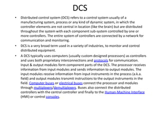
This document provides a comprehensive overview of instrumentation engineering, focusing on the measurement and control of process systems. It covers key terminologies related to transducers, pressure, level, flow, and temperature measurement, as well as the operation of various instruments and devices like control valves and automation systems. The text elaborates on the design, types, and applications of sensors, transmitters, and control systems in industrial settings.


![38
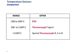
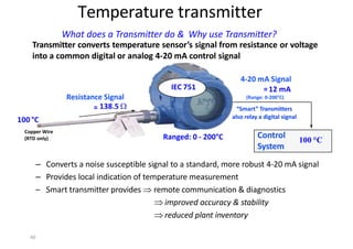
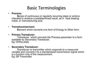
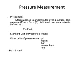
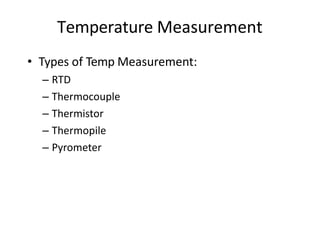
Temperature Sensors
RTDs
• How does a RTD works?
– Resistance changes are Repeatable
– The resistance changes of the platinum wiring can be
approximated by an ideal curve ‐‐ the IEC 751
0
50
100
150
200
250
300
350
-400 -200 0 200 400 600
Temperature (oC)
800
Resistance
(Ohms)
oC Ohms
0
10
20
30
100.00
103.90
107.79
111.67
International Resistance
vs. Temperature Chart:
IEC 751
IEC
751
IEC 751 Constants are :‐ A = 0.0039083, B = ‐ 5.775 x 10 ‐7,
If t>=0°C, C=0, If t<0, C = ‐ 4.183 x 10 ‐12
Example: RT = R0 [1 + At + Bt2 + C(t-100)t3]
= 103.90](https://image.slidesharecdn.com/instrumentationmain-240419144505-5c11c666/85/instrumentation-measurement-actvitvities-38-320.jpg)