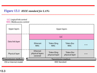
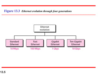
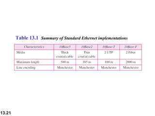
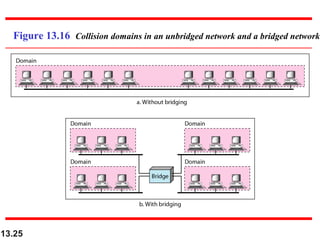
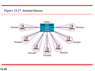
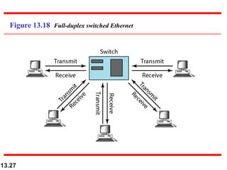
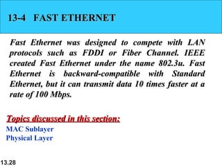
Chapter 13
Wired LANs: Ethernet

13.1

Copyright © The McGraw-Hill Companies, Inc. Permission required for reproduction or display.
13-1 IEEE STANDARDS
In 1985, the Computer Society of the IEEE started a
project, called Project 802, to set standards to enable
intercommunication among equipment from a variety
of manufacturers. Project 802 is a way of specifying
functions of the physical layer and the data link layer
of major LAN protocols.
Topics discussed in this section:
Data Link Layer
Physical Layer
13.2
Figure 13.1 IEEE standard for LANs

13.3
13-2 STANDARD ETHERNET
The original Ethernet was created in 1976 at Xerox’s
Palo Alto Research Center (PARC). Since then, it has
gone through four generations. We briefly discuss the
Standard (or traditional) Ethernet in this section.

Topics discussed in this section:
MAC Sublayer
Physical Layer

13.4
Figure 13.3 Ethernet evolution through four generations

13.5
Figure 13.4 802.3 MAC frame

13.6
Figure 13.5 Minimum and maximum lengths

13.7
Note

Frame length:
Minimum: 64 bytes (512 bits)
Maximum: 1518 bytes (12,144 bits)

13.8
Figure 13.6 Example of an Ethernet address in hexadecimal notation

13.9
Figure 13.7 Unicast and multicast addresses

13.10
Note

The least significant bit of the first byte
defines the type of address.
If the bit is 0, the address is unicast;
otherwise, it is multicast.

13.11
Note

The broadcast destination address is a
special case of the multicast address in
which all bits are 1s.

13.12
Example 13.1
Define the type of the following destination addresses:
a. 4A:30:10:21:10:1A
b. 47:20:1B:2E:08:EE
c. FF:FF:FF:FF:FF:FF
Solution
To find the type of the address, we need to look at the
second hexadecimal digit from the left. If it is even, the
address is unicast. If it is odd, the address is multicast. If
all digits are F’s, the address is broadcast. Therefore, we
have the following:
a. This is a unicast address because A in binary is 1010.
b. This is a multicast address because 7 in binary is 0111.
c. This is a broadcast address because all digits are F’s.
13.13
Example 13.2
Show how the address 47:20:1B:2E:08:EE is sent out on
line.
Solution
The address is sent left-to-right, byte by byte; for each
byte, it is sent right-to-left, bit by bit, as shown below:

13.14
Figure 13.8 Categories of Standard Ethernet

13.15
Figure 13.9 Encoding in a Standard Ethernet implementation

13.16
Figure 13.10 10Base5 implementation

13.17
Figure 13.11 10Base2 implementation

13.18
Figure 13.12 10Base-T implementation

13.19
Figure 13.13 10Base-F implementation

13.20
Table 13.1 Summary of Standard Ethernet implementations

13.21
13-3 CHANGES IN THE STANDARD
The 10-Mbps Standard Ethernet has gone through
several changes before moving to the higher data
rates. These changes actually opened the road to the
evolution of the Ethernet to become compatible with
other high-data-rate LANs.
Topics discussed in this section:
Bridged Ethernet
Switched Ethernet
Full-Duplex Ethernet
13.22
Figure 13.14 Sharing bandwidth

13.23
Figure 13.15 A network with and without a bridge

13.24
Figure 13.16 Collision domains in an unbridged network and a bridged network

13.25
Figure 13.17 Switched Ethernet

13.26
Figure 13.18 Full-duplex switched Ethernet

13.27
13-4 FAST ETHERNET
Fast Ethernet was designed to compete with LAN
protocols such as FDDI or Fiber Channel. IEEE
created Fast Ethernet under the name 802.3u. Fast
Ethernet is backward-compatible with Standard
Ethernet, but it can transmit data 10 times faster at a
rate of 100 Mbps.
Topics discussed in this section:
MAC Sublayer
Physical Layer
13.28
Figure 13.19 Fast Ethernet topology

13.29
Figure 13.20 Fast Ethernet implementations

13.30
Figure 13.21 Encoding for Fast Ethernet implementation

13.31
Table 13.2 Summary of Fast Ethernet implementations

13.32
13-5 GIGABIT ETHERNET
The need for an even higher data rate resulted in the
design of the Gigabit Ethernet protocol (1000 Mbps).
The IEEE committee calls the standard 802.3z.

Topics discussed in this section:
MAC Sublayer
Physical Layer
Ten-Gigabit Ethernet
13.33
Note

In the full-duplex mode of Gigabit
Ethernet, there is no collision;
the maximum length of the cable is
determined by the signal attenuation
in the cable.

13.34
Figure 13.22 Topologies of Gigabit Ethernet

13.35
Figure 13.23 Gigabit Ethernet implementations

13.36
Figure 13.24 Encoding in Gigabit Ethernet implementations

13.37
Table 13.3 Summary of Gigabit Ethernet implementations

13.38
Table 13.4 Summary of Ten-Gigabit Ethernet implementations

13.39

10 wired lan

  • 1.
    Chapter 13 Wired LANs:Ethernet 13.1 Copyright © The McGraw-Hill Companies, Inc. Permission required for reproduction or display.
  • 2.
    13-1 IEEE STANDARDS In1985, the Computer Society of the IEEE started a project, called Project 802, to set standards to enable intercommunication among equipment from a variety of manufacturers. Project 802 is a way of specifying functions of the physical layer and the data link layer of major LAN protocols. Topics discussed in this section: Data Link Layer Physical Layer 13.2
  • 3.
    Figure 13.1 IEEEstandard for LANs 13.3
  • 4.
    13-2 STANDARD ETHERNET Theoriginal Ethernet was created in 1976 at Xerox’s Palo Alto Research Center (PARC). Since then, it has gone through four generations. We briefly discuss the Standard (or traditional) Ethernet in this section. Topics discussed in this section: MAC Sublayer Physical Layer 13.4
  • 5.
    Figure 13.3 Ethernetevolution through four generations 13.5
  • 6.
    Figure 13.4 802.3MAC frame 13.6
  • 7.
    Figure 13.5 Minimumand maximum lengths 13.7
  • 8.
    Note Frame length: Minimum: 64bytes (512 bits) Maximum: 1518 bytes (12,144 bits) 13.8
  • 9.
    Figure 13.6 Exampleof an Ethernet address in hexadecimal notation 13.9
  • 10.
    Figure 13.7 Unicastand multicast addresses 13.10
  • 11.
    Note The least significantbit of the first byte defines the type of address. If the bit is 0, the address is unicast; otherwise, it is multicast. 13.11
  • 12.
    Note The broadcast destinationaddress is a special case of the multicast address in which all bits are 1s. 13.12
  • 13.
    Example 13.1 Define thetype of the following destination addresses: a. 4A:30:10:21:10:1A b. 47:20:1B:2E:08:EE c. FF:FF:FF:FF:FF:FF Solution To find the type of the address, we need to look at the second hexadecimal digit from the left. If it is even, the address is unicast. If it is odd, the address is multicast. If all digits are F’s, the address is broadcast. Therefore, we have the following: a. This is a unicast address because A in binary is 1010. b. This is a multicast address because 7 in binary is 0111. c. This is a broadcast address because all digits are F’s. 13.13
  • 14.
    Example 13.2 Show howthe address 47:20:1B:2E:08:EE is sent out on line. Solution The address is sent left-to-right, byte by byte; for each byte, it is sent right-to-left, bit by bit, as shown below: 13.14
  • 15.
    Figure 13.8 Categoriesof Standard Ethernet 13.15
  • 16.
    Figure 13.9 Encodingin a Standard Ethernet implementation 13.16
  • 17.
    Figure 13.10 10Base5implementation 13.17
  • 18.
    Figure 13.11 10Base2implementation 13.18
  • 19.
    Figure 13.12 10Base-Timplementation 13.19
  • 20.
    Figure 13.13 10Base-Fimplementation 13.20
  • 21.
    Table 13.1 Summaryof Standard Ethernet implementations 13.21
  • 22.
    13-3 CHANGES INTHE STANDARD The 10-Mbps Standard Ethernet has gone through several changes before moving to the higher data rates. These changes actually opened the road to the evolution of the Ethernet to become compatible with other high-data-rate LANs. Topics discussed in this section: Bridged Ethernet Switched Ethernet Full-Duplex Ethernet 13.22
  • 23.
    Figure 13.14 Sharingbandwidth 13.23
  • 24.
    Figure 13.15 Anetwork with and without a bridge 13.24
  • 25.
    Figure 13.16 Collisiondomains in an unbridged network and a bridged network 13.25
  • 26.
    Figure 13.17 SwitchedEthernet 13.26
  • 27.
    Figure 13.18 Full-duplexswitched Ethernet 13.27
  • 28.
    13-4 FAST ETHERNET FastEthernet was designed to compete with LAN protocols such as FDDI or Fiber Channel. IEEE created Fast Ethernet under the name 802.3u. Fast Ethernet is backward-compatible with Standard Ethernet, but it can transmit data 10 times faster at a rate of 100 Mbps. Topics discussed in this section: MAC Sublayer Physical Layer 13.28
  • 29.
    Figure 13.19 FastEthernet topology 13.29
  • 30.
    Figure 13.20 FastEthernet implementations 13.30
  • 31.
    Figure 13.21 Encodingfor Fast Ethernet implementation 13.31
  • 32.
    Table 13.2 Summaryof Fast Ethernet implementations 13.32
  • 33.
    13-5 GIGABIT ETHERNET Theneed for an even higher data rate resulted in the design of the Gigabit Ethernet protocol (1000 Mbps). The IEEE committee calls the standard 802.3z. Topics discussed in this section: MAC Sublayer Physical Layer Ten-Gigabit Ethernet 13.33
  • 34.
    Note In the full-duplexmode of Gigabit Ethernet, there is no collision; the maximum length of the cable is determined by the signal attenuation in the cable. 13.34
  • 35.
    Figure 13.22 Topologiesof Gigabit Ethernet 13.35
  • 36.
    Figure 13.23 GigabitEthernet implementations 13.36
  • 37.
    Figure 13.24 Encodingin Gigabit Ethernet implementations 13.37
  • 38.
    Table 13.3 Summaryof Gigabit Ethernet implementations 13.38
  • 39.
    Table 13.4 Summaryof Ten-Gigabit Ethernet implementations 13.39