Download to read offline
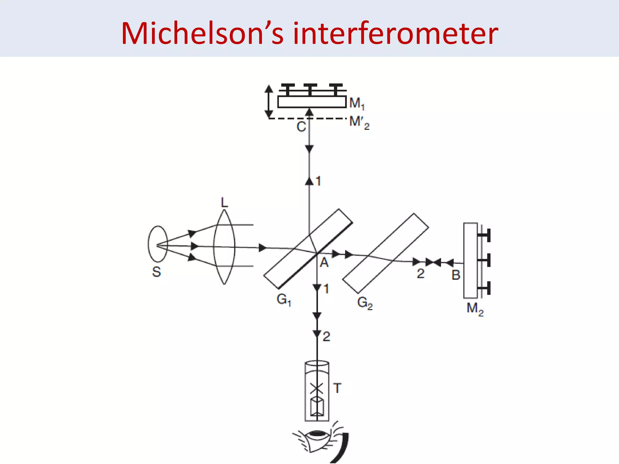
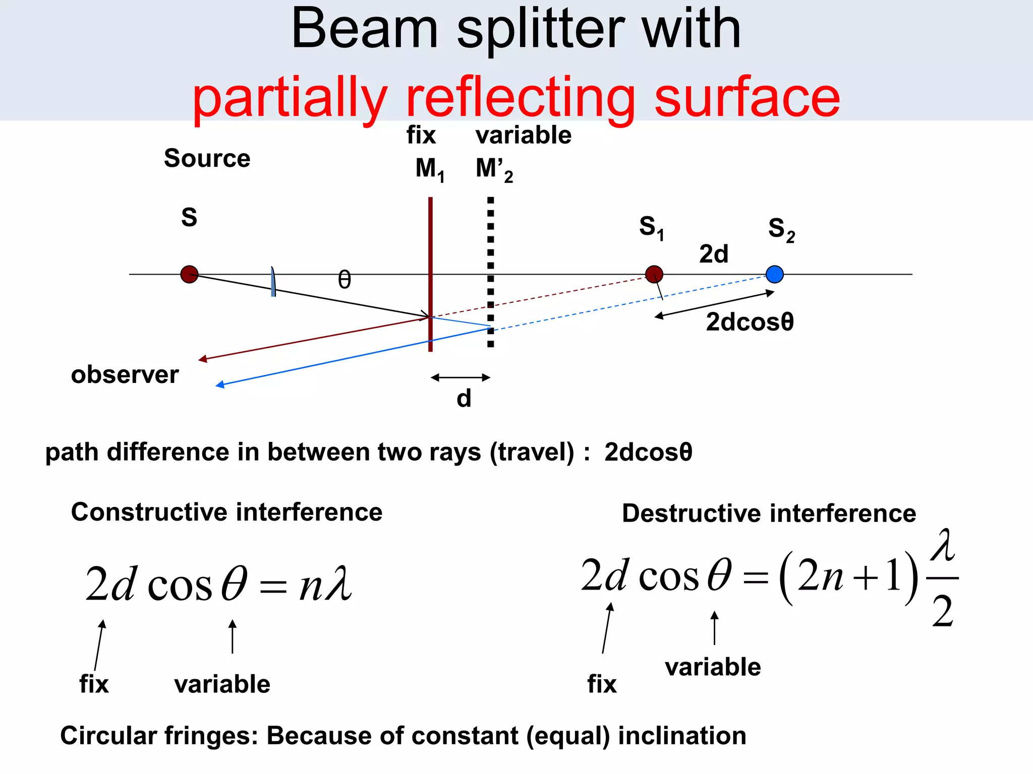


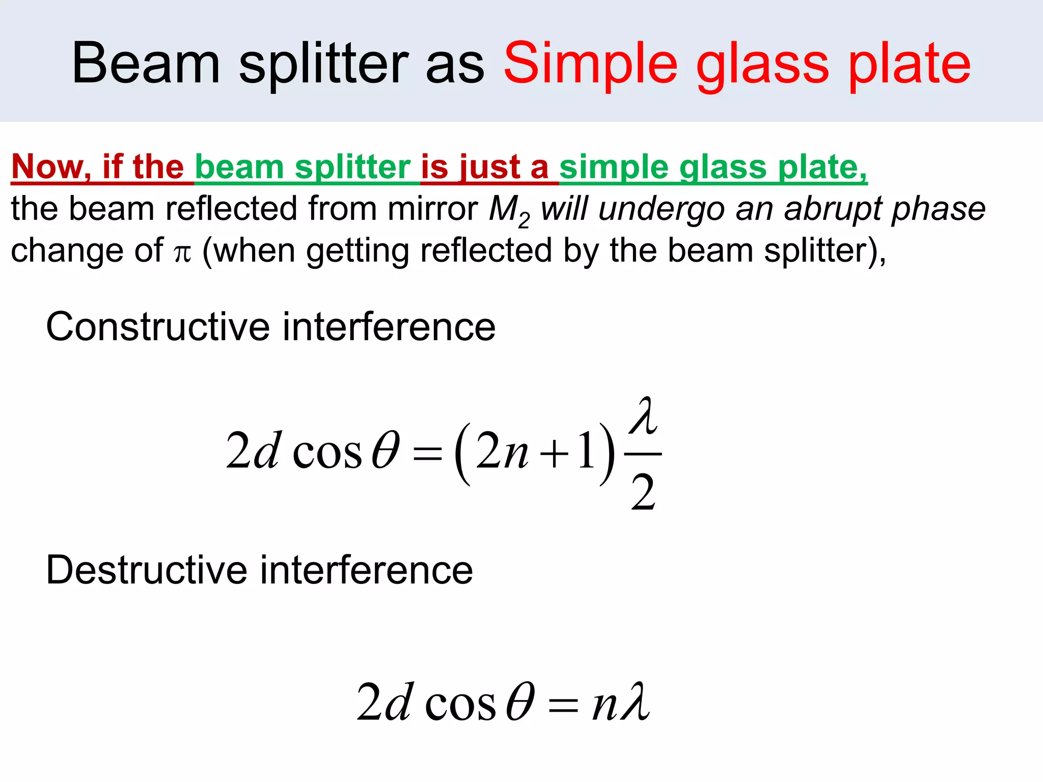


1. Michelson's interferometer uses a beam splitter to split light into two beams that travel different paths and are recombined, creating interference patterns of light and dark fringes. 2. The document discusses the conditions for constructive and destructive interference for Michelson's interferometer and how changing the orientation of the mirrors or using a glass plate as the beam splitter affects the interference patterns. 3. Methods for using Michelson's interferometer to determine properties are described, such as finding the wavelength of light, measuring differences in wavelengths, and determining the refractive index or thickness of transparent materials.


