Downloaded 1,469 times

![Young’s Double Slit Experiment:
•S
S• O
P
D
S1
S2
d
y
d/2
d/2
Single Slit Double Slit
Screen
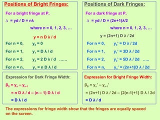
The waves from S1 and S2 reach the point P with
some phase difference and hence path difference
∆ = S2P – S1P
S2P2
– S1P2
= [D2
+ {y + (d/2)}2
] - [D2
+ {y - (d/2)}2
]
(S2P – S1P) (S2P + S1P) = 2 yd ∆ (2D) = 2 yd ∆ = yd / D](https://image.slidesharecdn.com/3waveoptics1-140315130819-phpapp02/85/Wave-Optics-Class-12-Part-1-13-320.jpg)

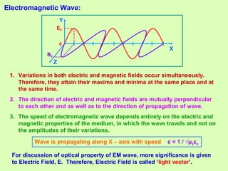
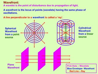
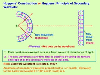
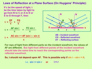
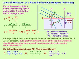
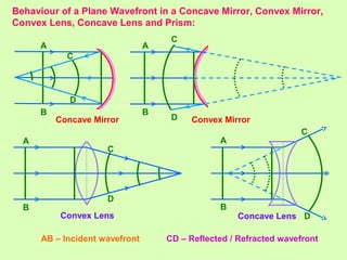
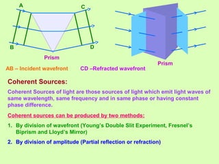
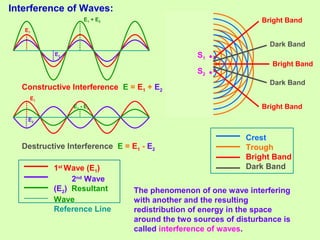
1. Light behaves as a wave and can interfere with itself when it takes multiple paths. Huygens' principle states that each point on a wavefront is a source of secondary wavelets which combine to form the new wavefront. 2. Interference occurs when two waves superimpose, with constructive and destructive interference occurring depending on the path difference between the waves. Young's double slit experiment demonstrated interference and bright and dark fringes formed on the screen. 3. Thin films can produce interference and appear colored due to the path differences between light rays reflecting and refracting within the film, with different colors seen for different path differences satisfying the interference conditions.