The document provides an overview of basic electronics concepts including:
- Basic circuit analysis including Ohm's law, resistors and capacitors in series/parallel, and voltage dividers.
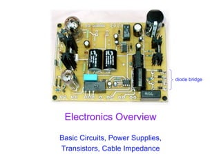
- Power supplies including diode bridges to convert AC to DC, smoothing capacitors, voltage regulators like zener diodes and voltage regulator ICs, and switching power supplies.
- Semiconductor devices like diodes, LEDs, transistors and how they can be used as switches or amplifiers.
The document examines these concepts through examples and diagrams to explain fundamental electronics topics at a high level.
It is very useful for medical entrance exams civil services exam SSC exams which is one of the best for your exams which is one shot of my own fault in our English Hindi dictionary is se jyada bhartiyan ki jayengi to nhi
Semiconductor
If a valence Electron acquires sufficient kinetic energy to break its covalent bond and fills the void created by a hole then a vacancy, or hole will be created in the covalent bond that released the electron
Hence there is a transfer of holes to the left and electrons to the right
Ch2-Diode.for electrical and computer engineeringabdiihuseen31
Diode best ppt
Tjststdiitdtditdidydtdo5di5ditdotdotdo5ditdo6dykdmgdjtsu4si4zzjfnzbdzbdHeqwi4sjrznfzhfzirs4s85sktxmgxkts8sktdgmxoydi5ei5ei5dktxktei5ei5e
Ch2-Diode.for electrical and computer engineeringabdiihuseen31
Diode best ppt
Tjststdiitdtditdidydtdo5di5ditdotdotdo5ditdo6dykdmgdjtsu4si4zzjfnzbdzbdHeqwi4sjrznfzhfzirs4s85sktxmgxkts8sktdgmxoydi5ei5ei5dktxktei5ei5e
2024.06.01 Introducing a competency framework for languag learning materials ...Sandy Millin
http://sandymillin.wordpress.com/iateflwebinar2024
Published classroom materials form the basis of syllabuses, drive teacher professional development, and have a potentially huge influence on learners, teachers and education systems. All teachers also create their own materials, whether a few sentences on a blackboard, a highly-structured fully-realised online course, or anything in between. Despite this, the knowledge and skills needed to create effective language learning materials are rarely part of teacher training, and are mostly learnt by trial and error.
Knowledge and skills frameworks, generally called competency frameworks, for ELT teachers, trainers and managers have existed for a few years now. However, until I created one for my MA dissertation, there wasn’t one drawing together what we need to know and do to be able to effectively produce language learning materials.
This webinar will introduce you to my framework, highlighting the key competencies I identified from my research. It will also show how anybody involved in language teaching (any language, not just English!), teacher training, managing schools or developing language learning materials can benefit from using the framework.
How to Split Bills in the Odoo 17 POS ModuleCeline George
Bills have a main role in point of sale procedure. It will help to track sales, handling payments and giving receipts to customers. Bill splitting also has an important role in POS. For example, If some friends come together for dinner and if they want to divide the bill then it is possible by POS bill splitting. This slide will show how to split bills in odoo 17 POS.
Instructions for Submissions thorugh G- Classroom.pptxJheel Barad
This presentation provides a briefing on how to upload submissions and documents in Google Classroom. It was prepared as part of an orientation for new Sainik School in-service teacher trainees. As a training officer, my goal is to ensure that you are comfortable and proficient with this essential tool for managing assignments and fostering student engagement.
This is a presentation by Dada Robert in a Your Skill Boost masterclass organised by the Excellence Foundation for South Sudan (EFSS) on Saturday, the 25th and Sunday, the 26th of May 2024.
He discussed the concept of quality improvement, emphasizing its applicability to various aspects of life, including personal, project, and program improvements. He defined quality as doing the right thing at the right time in the right way to achieve the best possible results and discussed the concept of the "gap" between what we know and what we do, and how this gap represents the areas we need to improve. He explained the scientific approach to quality improvement, which involves systematic performance analysis, testing and learning, and implementing change ideas. He also highlighted the importance of client focus and a team approach to quality improvement.
Read| The latest issue of The Challenger is here! We are thrilled to announce that our school paper has qualified for the NATIONAL SCHOOLS PRESS CONFERENCE (NSPC) 2024. Thank you for your unwavering support and trust. Dive into the stories that made us stand out!
Welcome to TechSoup New Member Orientation and Q&A (May 2024).pdfTechSoup
In this webinar you will learn how your organization can access TechSoup's wide variety of product discount and donation programs. From hardware to software, we'll give you a tour of the tools available to help your nonprofit with productivity, collaboration, financial management, donor tracking, security, and more.
The Indian economy is classified into different sectors to simplify the analysis and understanding of economic activities. For Class 10, it's essential to grasp the sectors of the Indian economy, understand their characteristics, and recognize their importance. This guide will provide detailed notes on the Sectors of the Indian Economy Class 10, using specific long-tail keywords to enhance comprehension.
For more information, visit-www.vavaclasses.com
How to Make a Field invisible in Odoo 17Celine George
It is possible to hide or invisible some fields in odoo. Commonly using “invisible” attribute in the field definition to invisible the fields. This slide will show how to make a field invisible in odoo 17.
2. Winter 2012
UCSD: Physics 121; 2012
2
Basic Circuit Analysis
• What we won’t do:
– common electronics-class things: RLC, filters, detailed
analysis
• What we will do:
– set out basic relations
– look at a few examples of fundamental importance (mostly
resistive circuits)
– look at diodes, voltage regulation, transistors
– discuss impedances (cable, output, etc.)
3. Winter 2012
UCSD: Physics 121; 2012
3
The Basic Relations
• V is voltage (volts: V); I is current (amps: A); R is
resistance (ohms: ); C is capacitance (farads: F); L
is inductance (henrys: H)
• Ohm’s Law: V = IR; V = ; V = L(dI/dt)
• Power: P = IV = V2/R = I2R
• Resistors and inductors in series add
• Capacitors in parallel add
• Resistors and inductors in parallel, and capacitors in
series add according to:
4. Winter 2012
UCSD: Physics 121; 2012
4
Example: Voltage divider
• Voltage dividers are a classic way to
set a voltage
• Works on the principle that all charge
flowing through the first resistor goes
through the second
– so V R-value
– provided any load at output is
negligible: otherwise some current
goes there too
• So Vout = V(R2/(R1 + R2))
• R2 here is a variable resistor, or
potentiometer, or “pot”
– typically three terminals: R12 is fixed,
tap slides along to vary R13 and R23,
though R13 + R23 = R12 always
1
2
3
R1
R2
V Vout
5. Winter 2012
UCSD: Physics 121; 2012
5
Real Batteries: Output Impedance
• A power supply (battery) is characterized by a
voltage (V) and an output impedance (R)
– sometimes called source impedance
• Hooking up to load: Rload, we form a voltage
divider, so that the voltage applied by the battery
terminal is actually Vout = V(Rload/(R+Rload))
– thus the smaller R is, the “stiffer” the power supply
– when Vout sags with higher load current, we call
this “droop”
• Example: If 10.0 V power supply droops by 1%
(0.1 V) when loaded to 1 Amp (10 load):
– internal resistance is 0.1
– called output impedance or source impedance
– may vary with load, though (not a real resistor)
V
R
D-cell example: 6A
out of 1.5 V battery
indicates 0.25 output
impedance
6. Winter 2012
UCSD: Physics 121; 2012
6
Power Supplies and Regulation
• A power supply typically starts with a transformer
– to knock down the 340 V peak-to-peak (120 V AC) to something
reasonable/manageable
• We will be using a center-tap transformer
– (A’ B’) = (winding ratio)(A B)
• when A > B, so is A’ > B’
– geometry of center tap (CT) guarantees it is midway between A’
and B’ (frequently tie this to ground so that A’ = B’)
– note that secondary side floats: no ground reference built-in
A
B
A’
CT
B’
AC input AC output
7. Winter 2012
UCSD: Physics 121; 2012
7
Diodes
• Diodes are essentially one-way current gates
• Symbolized by:
• Current vs. voltage graphs:
V
I
V
I
V
I
V
I
0.6 V
plain resistor diode idealized diode WAY idealized diode
no current flows current flows
the direction the
arrow points in the
diode symbol is the
direction that current
will flow
acts just like a wire
(will support arbitrary
current) provided that
voltage is positive
8. Winter 2012
UCSD: Physics 121; 2012
8
Diode Makeup
• Diodes are made of semiconductors (usually silicon)
• Essentially a stack of p-doped and n-doped silicon to
form a p-n junction
– doping means deliberate impurities that contribute extra
electrons (n-doped) or “holes” for electrons (p-doped)
• Transistors are n-p-n or p-n-p arrangements of
semiconductors
p-type n-type
9. Winter 2012
UCSD: Physics 121; 2012
9
LEDs: Light-Emitting Diodes
• Main difference is material is more exotic than silicon used in ordinary
diodes/transistors
– typically 2-volt drop instead of 0.6 V drop
• When electron flows through LED, loses energy by emitting a photon of
light rather than vibrating lattice (heat)
• LED efficiency is 30% (compare to incandescent bulb at 10%)
• Must supply current-limiting resistor in series:
– figure on 2 V drop across LED; aim for 1–10 mA of current
10. Winter 2012
UCSD: Physics 121; 2012
10
Getting DC back out of AC
• AC provides a means for us to distribute electrical
power, but most devices actually want DC
– bulbs, toasters, heaters, fans don’t care: plug straight in
– sophisticated devices care because they have diodes and
transistors that require a certain polarity
• rather than oscillating polarity derived from AC
• this is why battery orientation matters in most electronics
• Use diodes to “rectify” AC signal
• Simplest (half-wave) rectifier uses one diode:
AC source load
input voltage
voltage seen by load
diode only conducts
when input voltage is positive
11. Winter 2012
UCSD: Physics 121; 2012
11
Doing Better: Full-wave Diode Bridge
• The diode in the rectifying circuit simply prevented
the negative swing of voltage from conducting
– but this wastes half the available cycle
– also very irregular (bumpy): far from a “good” DC source
• By using four diodes, you can recover the negative
swing:
A
C
B
D
AC source
load
input voltage
voltage seen by load
B & C conduct
A & D conduct
12. Winter 2012
UCSD: Physics 121; 2012
12
Full-Wave Dual-Supply
• By grounding the center tap, we have two opposite
AC sources
– the diode bridge now presents + and voltages relative to
ground
– each can be separately smoothed/regulated
– cutting out diodes A and D makes a half-wave rectifier
A
C
B
D
AC source
+ load
load
voltages seen by loads
can buy pre-packaged diode bridges
13. Winter 2012
UCSD: Physics 121; 2012
13
Smoothing out the Bumps
• Still a bumpy ride, but we can smooth this out with a
capacitor
– capacitors have capacity for storing charge
– acts like a reservoir to supply current during low spots
– voltage regulator smoothes out remaining ripple
A
C
B
D
AC source
load
capacitor
14. Winter 2012
UCSD: Physics 121; 2012
14
How smooth is smooth?
• An RC circuit has a time constant = RC
– because dV/dt = I/C, and I = V/R dV/dt = V/RC
– so V is V0exp(t/)
• Any exponential function starts out with slope =
Amplitude/
• So if you want < 10% ripple over 120 Hz (8.3 ms)
timescale…
– must have = RC > 83 ms
– if R = 100 , C > 830 F
R
C
V
15. Winter 2012
UCSD: Physics 121; 2012
15
Regulating the Voltage
• The unregulated, ripply voltage may not be at the
value you want
– depends on transformer, etc.
– suppose you want 15.0 V
• You could use a voltage divider to set the voltage
• But it would droop under load
– output impedance R1 || R2
– need to have very small R1, R2 to make “stiff”
– the divider will draw a lot of current
– perhaps straining the source
– power expended in divider >> power in load
• Not a “real” solution
• Important note: a “big load” means a small resistor
value: 1 demands more current than 1 M
1
2
3
R1
R2
Vin
Vout
Rload
16. Winter 2012
UCSD: Physics 121; 2012
16
The Zener Regulator
• Zener diodes break down at some reverse
voltage
– can buy at specific breakdown voltages
– as long as some current goes through
zener, it’ll work
– good for rough regulation
• Conditions for working:
– let’s maintain some minimal current, Iz
through zener (say a few mA)
– then (Vin Vout)/R1 = Iz + Vout/Rload sets the
requirement on R1
– because presumably all else is known
– if load current increases too much, zener
shuts off (node drops below breakdown)
and you just have a voltage divider with the
load
R1
Z
Vin
Vout = Vz
Rload
zener voltage
high slope is what makes the
zener a decent voltage regulator
17. Winter 2012
UCSD: Physics 121; 2012
17
Voltage Regulator IC
• Can trim down ripply voltage to
precise, rock-steady value
• Now things get complicated!
– We are now in the realm of
integrated circuits (ICs)
• ICs are whole circuits in small
packages
• ICs contain resistors,
capacitors, diodes, transistors,
etc.
note zeners
18. Winter 2012
UCSD: Physics 121; 2012
18
Voltage Regulators
• The most common voltage regulators are the
LM78XX (+ voltages) and LM79XX ( voltages)
– XX represents the voltage
• 7815 is +15; 7915 is 15; 7805 is +5, etc
– typically needs input > 3 volts above output (reg.) voltage
• A versatile regulator is the LM317 (+) or LM337 ()
– 1.2–37 V output
– Vout = 1.25(1+R2/R1) + IadjR2
– Up to 1.5 A
– picture at right can go to 25 V
– datasheetcatalog.com for details
beware that housing is not always ground
19. Winter 2012
UCSD: Physics 121; 2012
19
Transistors
• Transistors are versatile, highly non-linear
devices
• Two frequent modes of operation:
– amplifiers/buffers
– switches
• Two main flavors:
– npn (more common) or pnp, describing doping
structure
• Also many varieties:
– bipolar junction transistors (BJTs) such as npn, pnp
– field effect transistors (FETs): n-channel and p-
channel
– metal-oxide-semiconductor FETs (MOSFETs)
• We’ll just hit the essentials of the BJT here
– MOSFET in later lecture
B
C
E
B
E
C
npn pnp
20. Winter 2012
UCSD: Physics 121; 2012
20
BJT Amplifier Mode
• Central idea is that when in the right regime, the BJT
collector-emitter current is proportional to the base
current:
– namely, Ice = Ib, where (sometimes hfe) is typically ~100
– In this regime, the base-emitter voltage is ~0.6 V
– below, Ib = (Vin 0.6)/Rb; Ice = Ib = (Vin 0.6)/Rb
– so that Vout = Vcc IceRc = Vcc (Vin 0.6)(Rc/Rb)
– ignoring DC biases, wiggles on Vin become (Rc/Rb) bigger
(and inverted): thus amplified
out
Rc
Rb
in
Vcc
B
C
E
21. Winter 2012
UCSD: Physics 121; 2012
21
Switching: Driving to Saturation
• What would happen if the base current is so big that
the collector current got so big that the voltage drop
across Rc wants to exceed Vcc?
– we call this saturated: Vc Ve cannot dip below ~0.2 V
– even if Ib is increased, Ic won’t budge any more
• The example below is a good logic inverter
– if Vcc = 5 V; Rc = 1 k; Ic(sat) 5 mA; need Ib > 0.05 mA
– so Rb < 20 k would put us safely into saturation if Vin = 5V
– now 5 V in ~0.2 V out; < 0.6 V in 5 V out
out
Rc
Rb
in
Vcc
22. Winter 2012
UCSD: Physics 121; 2012
22
Transistor Buffer
• In the hookup above (emitter follower), Vout = Vin 0.6
– sounds useless, right?
– there is no voltage “gain,” but there is current gain
– Imagine we wiggle Vin by V: Vout wiggles by the same V
– so the transistor current changes by Ie = V/R
– but the base current changes 1/ times this (much less)
– so the “wiggler” thinks the load is V/Ib = ·V/Ie = R
– the load therefore is less formidable
• The “buffer” is a way to drive a load without the driver
feeling the pain (as much): it’s impedance isolation
out
R
in
Vcc
23. Winter 2012
UCSD: Physics 121; 2012
23
Improved Zener Regulator
• By adding a transistor to the zener
regulator from before, we no longer
have to worry as much about the current
being pulled away from the zener to the
load
– the base current is small
– Rload effectively looks times bigger
– real current supplied through transistor
• Can often find zeners at 5.6 V, 9.6 V,
12.6 V, 15.6 V, etc. because drop from
base to emitter is about 0.6 V
– so transistor-buffered Vreg comes out to
5.0, 9.0, etc.
• Iz varies less in this arrangement, so the
regulated voltage is steadier
Vreg
Rload
Vz
Vin
Rz
Z
Vin
24. Winter 2012
UCSD: Physics 121; 2012
24
Switching Power Supplies
• Power supplies without transformers
– lightweight; low cost
– can be electromagnetically noisy
• Use a DC-to-DC conversion process
that relies on flipping a switch on and
off, storing energy in an inductor and
capacitor
– regulators were DC-to-DC converters too,
but lossy: lose P = IV of power for
voltage drop of V at current I
– regulators only down-convert, but
switchers can also up-convert
– switchers are reasonably efficient at
conversion
25. Winter 2012
UCSD: Physics 121; 2012
25
Switcher topologies
from: http://www.maxim-ic.com/appnotes.cfm/appnote_number/4087
The FET switch is turned off or on in a pulse-width-modulation (PWM) scheme,
the duty cycle of which determines the ratio of Vout to Vin
26. Winter 2012
UCSD: Physics 121; 2012
26
Step-Down Calculations
• If the FET is on for duty cycle, D (fraction of time on),
and the period is T:
– the average output voltage is Vout = DVin
– the average current through the capacitor is zero, the
average current through the load (and inductor) is 1/D times
the input current
– under these idealizations, power in = power out
27. Winter 2012
UCSD: Physics 121; 2012
27
Step-down waveforms
• Shown here is an example of
the step-down with the FET
duty cycle around 75%
• The average inductor current
(dashed) is the current
delivered to the load
– the balance goes to the
capacitor
• The ripple (parabolic sections)
has peak-to-peak fractional
amplitude of T2(1D)/(8LC)
– so win by small T, large L & C
– 10 kHz at 1 mH, 1000 F
yields ~0.1% ripple
– means 10 mV on 10 V
FET
Inductor
Current
Supply
Current
Capacitor
Current
Output
Voltage
(ripple exag.)
28. Winter 2012
UCSD: Physics 121; 2012
28
Cable Impedances
• RG58 cable is characterized as 50 cable
– RG59 is 75
– some antenna cable is 300
• Isn’t the cable nearly zero resistance? And shouldn’t
the length come into play, somehow?
• There is a distinction between resistance and
impedance
– though same units
• Impedances can be real, imaginary, or complex
– resistors are real: Z = R
– capacitors and inductors are imaginary: Z = i/C; Z = iL
– mixtures are complex: Z = R i/C + iL
29. Winter 2012
UCSD: Physics 121; 2012
29
Impedances, cont.
• Note that:
– capacitors become less “resistive” at high frequency
– inductors become more “resistive” at high frequency
– bigger capacitors are more transparent
– bigger inductors are less transparent
– i (√1) indicates 90 phase shift between voltage and current
• after all, V = IZ, so Z = V/I
• thus if V is sine wave, I is cosine for inductor/capacitor
• and given that one is derivative, one is integral, this makes
sense (slide # 3)
– adding impedances automatically takes care of summation
rules: add Z in series
• capacitance adds as inverse, resistors, inductors straight-up
30. Winter 2012
UCSD: Physics 121; 2012
30
Impedance Phasor Diagram
• Impedances can be drawn
on a complex plane, with
pure resistive, inductive, and
capacitive impedances
represented by the three
cardinal arrows
• An arbitrary combination of
components may have a
complex impedance, which
can be broken into real and
imaginary parts
• Note that a system’s
impedance is frequency-
dependent
R
L
Z
Zr
Zi
1/C
real axis
imag. axis
31. Winter 2012
UCSD: Physics 121; 2012
31
Transmission Line Model
• The cable has a finite capacitance per unit length
– property of geometry and dielectric separating conductors
– C/l = 2πε/ln(b/a), where b and a are radii of cylinders
• Also has an inductance per unit length
– L/l = (μ/2π)ln(b/a)
• When a voltage is applied, capacitors charge up
– thus draw current; propagates down the line near speed of light
• Question: what is the ratio of voltage to current?
– because this is the characteristic impedance
• Answer: Z0 = sqrt(L/C) = sqrt(L/C) = (1/2π)sqrt(μ/ε)ln(b/a)
– note that Z0 is frequency-independent
C
L
input output
32. Winter 2012
UCSD: Physics 121; 2012
32
Typical Transmission Lines
• RG58 coax is abundant
– 30 pF per foot; 75 nH per foot; 50 ; v = 0.695c; ~5 ns/m
• RG174 is the thin version
– same parameters as above, but scaled-down geometry
• RG59
– used for video, cable TV
– 21 pF/ft; 118 nH per foot; 75 ; v = 0.695c; ~5 ns/m
• twisted pair
– 110 at 30 turns/ft, AWG 24–28
• PCB (PC-board) trace
– get 50 if the trace width is 1.84 times the separation from
the ground plane (assuming fiberglass PCB with = 4.5)
33. Winter 2012
UCSD: Physics 121; 2012
33
Why impedance matters
• For fast signals, get bounces (reflections) at every
impedance mismatch
– reflection amplitude is (Zt Zs)/(Zt + Zs)
• s and t subscripts represent source and termination
impedances
• sources intending to drive a Z0 cable have Zs = Z0
• Consider a long cable shorted at end: insert pulse
– driving electronics can’t know about the termination
immediately: must charge up cable as the pulse propagates
forward, looking like Z0 of the cable at first
– surprise at far end: it’s a short! retreat!
– in effect, negative pulse propagates back, nulling out
capacitors (reflection is 1)
– one round-trip later (10 ns per meter, typically), the driving
electronics feels the pain of the short
34. Winter 2012
UCSD: Physics 121; 2012
34
Impedance matters, continued
• Now other extreme: cable un-terminated: open
– pulse travels merrily along at first, the driving electronics
seeing a Z0 cable load
– at the end, the current has nowhere to go, but driver can’t
know this yet, so keeps loading cable as if it’s still Z0
– effectively, a positive pulse reflects back, double-charging
capacitors (reflection is +1)
– driver gets word of this one round-trip later (10 ns/m,
typically), then must cease to deliver current (cable fully
charged)
• The goldilocks case (reflection = 0)
– if the end of the cable is terminated with resistor with R = Z0,
then current is slurped up perfectly with no reflections
– the driver is not being lied to, and hears no complaints
35. Winter 2012
UCSD: Physics 121; 2012
35
So Beware!
• If looking at fast (tens of ns domain) signals on
scope, be sure to route signal to scope via 50 coax
and terminate the scope in 50
– if the signal can’t drive 50 , then use active probes
• Note that scope probes terminate to 1 M, even
though the cables are NOT 1 M cables (no such
thing)
– so scope probes can be very misleading about shapes of
fast signals
36. Winter 2012
UCSD: Physics 121; 2012
36
References and Assignment
• References:
– The canonical electronics reference is Horowitz and Hill: The
Art of Electronics
– Also the accompanying lab manual by Hayes and Horowitz
is highly valuable (far more practically-oriented)
– And of course: Electronics for Dogs (just ask Gromit)
• Reading
– Sections 6.1.1, 6.1.2
– Skim 6.2.2, 6.2.3, 6.2.4
– Sections 6.3.1, 6.5.1, 6.5.2
– Skim 6.3.2