This document discusses the history and technical background of design drift requirements in building codes. It explains that code provisions for calculating seismic drift have changed substantially over the past 40 years, though the reasons for these changes are not well documented. The document focuses on minimum base shear requirements for determining drift in long-period structures, and discusses the reasoning behind current code equations. It also explores the effects of drift on structural elements, nonstructural components, and adjacent buildings.
Earthquakes are very serious problems since they affect human life in various ways. The Earthquakes are mainly prevented by two methods namely Base Isolation Methods and Seismic Dampers. The present paper deals with 1.Increase natural period of structure by "Base Isolation Techniques".2.Increase damping of the system by "Energy Dissipation Devices". In brief manner. This paper explains the main theme of the above methods and their preventive methods about Earthquakes. The present paper deals with structures which resist Earthquakes. It explains the frames which help in resisting Earthquakes. In total, this present paper deals with Methods of resisting Earthquakes and Frames resisting them and also the prominent techniques followed to resist Earthquakes.
Earthquake Resistant Building ConstructionRohan Narvekar
This File comprises of a general information and guidelines for construction of Earthquake Resistant buildings, Its a basic study of the same and may help students and learners for overall information of this technology.
Earthquake-resistant structures are structures designed to protect buildings to some or greater extent from earthquakes. While no structure can be entirely immune to damage from earthquakes, the goal of earthquake-resistant construction is to erect structures that fare better during seismic activity than their conventional counterparts. According to building codes, earthquake-resistant structures are intended to withstand the largest earthquake of a certain probability that is likely to occur at their location. This means the loss of life should be minimized by preventing the collapse of the buildings for rare earthquakes while the loss of the functionality should be limited for more frequent ones
Basic points on earthquake resistant building
- Design considerations and different techniques employed to resist building from collapse during earthquake
Earthquake resistant structure By Engr. Ghulam Yasin TaunsviShan Khan
The resistance structure is structures designed to withstand earthquakes. While no structure can be entirely immune to damage from earthquakes, the goal of earthquake-resistant construction is to erect structures that fare better during seismic activity than their conventional counterparts.
this presentation is about how you can make a building more resistant to earthquakes. Different techniques and designs are discussed to make a building more resistant to earthquakes. examples of different earthquake resistant buildings are also discussed.
Architectural And Structural Design Of Blast Resistant Buildings - REPORTPaul Jomy
The objective of this study is to shed light on blast resistant building theories, the enhancement of building security against the effect of explosives in both architectural and structural design process and the design techniques that should be carried out. Firstly, explosives and explosion type have been explained briefly. In addition, the general aspects of explosion process have been presented to clarify the effect of explosives on buildings. To have a better understanding of explosives and characteristics of explosions will enable us to make blast resistant building design much more efficiently. Essential techniques for increasing the capacity of a building to provide protection against explosive effects is discussed both with an architectural and structural approach.
DESIGN AND ANALYSIS OF EARTH-QUAKE RESISTANT FOR MULTI-STORIED BUILDING ON A ...Ijripublishers Ijri
his project named as “DESIGN OF EARTH-QUAKE RESISTANT MULTI-STORIED RCC BUILDING ON A SLOPING
GROUND” involves the analysis of simple 2-D frames of varying floor heights and varying no of bays using a very popular
software tool STAAD Pro. Using the analysis results various graphs were drawn between the maximum axial force,
maximum shear force, maximum bending moment, maximum tensile force and maximum compressive stress being
developed for the frames on plane ground and sloping ground. The graphs used to drawn comparison between the two
cases and the detailed study of “SHORT COLOUMN EFFECT” failure was carried up. In addition to that the detailed
study of seismology was undertaken and the feasibility of the software tool to be used was also checked. Till date many
such projects have been undertaken on this very topic but the analysis were generally done for the static loads i.e. dead
load, live load etc, but to this the earthquake analysis or seismic analysis is to be incorporated. To create a technical
knowhow, two similar categories of structures were analyzed, first on plane ground and another on a sloping ground.
Then the results were compared. At last the a structure would be analyzed and designed on sloping ground for all possible
load combinations pertaining to IS 456, IS 1893 and IS 13920 manually.
PERFORMANCE BASED ANALYSIS OF VERTICALLY IRREGULAR STRUCTURE UNDER VARIOUS SE...Ijripublishers Ijri
In the recent years a lot of attention has been given to the earthquake analysis of structure it is one of the most devastating
natural calamity and which causes severe damage not only to the properties but also to the lives. This is the
reason there has been a lot of focus on the structures to be earthquake resistant. Buildings get damaged mostly due
to the earthquake ground motions. In an earthquake, the building base experiences high frequency movements, which
results in the inertial force on the building and its components and this problem gets worse when a structure is irregular
in shape, size etc,. Therefore, there is a lot to work on the seismic behavior of the irregular building which might not
respond the way regular building does. It makes the irregular building quite more complex and unpredictable during
the course of an earthquake.
Descriptive study of pushover analysis in rcc structures of rigid jointYousuf Dinar
ABSTRACT: Structures in mega cities, are under serious threat because of faulty and unskilled design and construction of structures. Sometimes structure designers are more concerned in constructing different load resistant members without knowing its necessity and its performance in the structure. Different configuration of construction may also lead to significant variation in capacity of the same structure. Nonlinear static pushover analysis provides a better view on the performance of the structures during seismic events. This comprehensive research evaluates as well as compares the performances of bare, different infill percentage level, different configuration of soft storey and Shear wall consisting building structures with each other and later depending upon the findings, suggests from which level of performance shear wall should be preferred over the infill structure and will eventually help engineers to decide where generally the soft storey could be constructed in the structures. Above all a better of effects of pushover analysis could be summarized from the findings. Masonry walls are represented by equivalent strut according to pushover concerned codes. For different loading conditions, the performances of structures are evaluated with the help of performance point, base shear, top displacement, storey drift and stages of number of hinges form.
Seismic pounding between adjacent rc buildings with and without base isolatio...eSAT Journals
Abstract Among the possible structural damages during an earthquake, the seismic induced pounding also has been one of the commonly observed phenomena. This is because the separation gap between many adjacent buildings is inadequate to accommodate the relative motions, so buildings vibrate out of phase and collides. Despite the fact that the seismic pounding between nearby structures is considered in the codal procurements, the act of development is still an issue in numerous metropolitan zones where the structures are built with no adequate partition separation which brings about their pounding. In this study E-Tabs nonlinear software is used for simulation of adjacent multi-storeyed RC frame buildings of G+14 and G+9 storey, the provisions that may reduce the effects of pounding like the separation distance, addition of shear walls, lateral bracings and variation in storey height of the buildings have been considered for analysis. And the responses like storey-displacement and pounding force by considering both fixed base and base-isolated conditions are arrived. Keywords: Seismic pounding, RC frame building, Separation distance, Gap elements, Storey-displacement Pounding force, Fixed-base, Base isolation.
Analysis and Capacity Based Earthquake Resistance Design of Multy Bay Multy S...IJERA Editor
Many reinforced concrete (RC) framed structures located in zones of high seismicity in India are constructed
without considering the seismic code provisions. The vulnerability of inadequately designed structures represents
seismic risk to occupants. The main cause of failure of multi-storey reinforced concrete frames during seismic
motion is the sway mechanism. If the frame is designed on the basis of strong column-weak beam concept the
possibilities of collapse due to sway mechanisms can be completely eliminated. In multi storey frame this can be
achieved by allowing the plastic hinges to form, in a predetermined sequence only at the ends of all the beams
while the columns remain essentially in elastic stage and by avoiding shear mode of failures in columns and
beams. This procedure for design is known as Capacity based design which would be the future design
philosophy for earthquake resistant design of multi storey reinforced concrete frames. Model of multi bay multi
storied residential building study were done using the software program ETAB2015 and were analyzed using
non-linear static pushover analysis
International Journal of Engineering Research and Applications (IJERA) is an open access online peer reviewed international journal that publishes research and review articles in the fields of Computer Science, Neural Networks, Electrical Engineering, Software Engineering, Information Technology, Mechanical Engineering, Chemical Engineering, Plastic Engineering, Food Technology, Textile Engineering, Nano Technology & science, Power Electronics, Electronics & Communication Engineering, Computational mathematics, Image processing, Civil Engineering, Structural Engineering, Environmental Engineering, VLSI Testing & Low Power VLSI Design etc.
A Review on Analysis of a Tall Structure with Shear Panel and Floating Columnsijtsrd
For effective design and good construction practises of multistory buildings, numerous prior studies have been conducted. When an earthquake strikes a palace, seismic stresses are produced at the buildings floor level. A variety of structure damage was seen after the earthquake. This study was conducted in seismic zone IV. In this work, we examine how tall structures with and without floating columns behave seismically. There are various situations in multistory buildings when it may be difficult to place a column in a certain spot.This study compares two multistory buildings, one of which supports its columns directly from the ground, and the other of which has floating columns in various locations. We prepared the model for the same height, the same plan, and the same loading condition for this analysis using the Staad Pro software. We are using an 11 story building with a 33.8 meter overall height and a layout that measures 18.92 by 19.78 metres for our analysis. There are 50 columns in the building, and 12 of them are supported by ground floor beams rather than the ground.These columns are termed as floating columns. We are providing a shear panels in those locations where the columns are supported. This shear wall transfers the load coming from the floating columns to the wall supporting columns. By considering these conditions we analysis both structures and find out the results of using floating columns in the same building. In this analysis to comparison of behavior of tall buildings using with and without floating column is concluded on parameters maximum beam moment, maximum beam shear and maximum nodal deflection and volume of concrete and volume of steel . By considering these conditions we analysis both structures and find out the results of using floating columns in the same building. Munish Kumar Singh | Prof. Afzal Khan "A Review on Analysis of a Tall Structure with Shear Panel and Floating Columns" Published in International Journal of Trend in Scientific Research and Development (ijtsrd), ISSN: 2456-6470, Volume-7 | Issue-2 , April 2023, URL: https://www.ijtsrd.com.com/papers/ijtsrd57440.pdf Paper URL: https://www.ijtsrd.com.com/engineering/civil-engineering/57440/a-review-on-analysis-of-a-tall-structure-with-shear-panel-and-floating-columns/munish-kumar-singh
Effect of Seismic Joint in the Performance of Multi-Storeyed L-Shaped BuildingIOSR Journals
The choices of building shapes and structural systems have significant effect on their seismic performance. While symmetrical buildings result in a fairly uniform distribution of seismic forces throughout its components. Unsymmetrical buildings result in highly indeterminate distribution of forces making the analysis and prediction more complicated. L-shaped buildings are among those unsymmetrical structures which are most commonly found in practice in the form of school, office, commercial buildings. In this work three dimensional models of L-shaped buildings are investigated for their seismic performance, varying bay length and storey height. These models were analysed for three conditions viz with gap, with seismic joint and with neither of these. The modeling of structures analysis is carried out using STAAD Pro V8i, also the performance is analysed providing brick infill and compared with, without infill condition. Performances is measured in terms of displacements, axial forces, bending moments, shear forces and compared for those conditions mentioned in the identified column viz., corner, intermediate and interior
Why You Should Replace Windows 11 with Nitrux Linux 3.5.0 for enhanced perfor...SOFTTECHHUB
The choice of an operating system plays a pivotal role in shaping our computing experience. For decades, Microsoft's Windows has dominated the market, offering a familiar and widely adopted platform for personal and professional use. However, as technological advancements continue to push the boundaries of innovation, alternative operating systems have emerged, challenging the status quo and offering users a fresh perspective on computing.
One such alternative that has garnered significant attention and acclaim is Nitrux Linux 3.5.0, a sleek, powerful, and user-friendly Linux distribution that promises to redefine the way we interact with our devices. With its focus on performance, security, and customization, Nitrux Linux presents a compelling case for those seeking to break free from the constraints of proprietary software and embrace the freedom and flexibility of open-source computing.
Epistemic Interaction - tuning interfaces to provide information for AI supportAlan Dix
Paper presented at SYNERGY workshop at AVI 2024, Genoa, Italy. 3rd June 2024
https://alandix.com/academic/papers/synergy2024-epistemic/
As machine learning integrates deeper into human-computer interactions, the concept of epistemic interaction emerges, aiming to refine these interactions to enhance system adaptability. This approach encourages minor, intentional adjustments in user behaviour to enrich the data available for system learning. This paper introduces epistemic interaction within the context of human-system communication, illustrating how deliberate interaction design can improve system understanding and adaptation. Through concrete examples, we demonstrate the potential of epistemic interaction to significantly advance human-computer interaction by leveraging intuitive human communication strategies to inform system design and functionality, offering a novel pathway for enriching user-system engagements.
The Art of the Pitch: WordPress Relationships and SalesLaura Byrne
Clients don’t know what they don’t know. What web solutions are right for them? How does WordPress come into the picture? How do you make sure you understand scope and timeline? What do you do if sometime changes?
All these questions and more will be explored as we talk about matching clients’ needs with what your agency offers without pulling teeth or pulling your hair out. Practical tips, and strategies for successful relationship building that leads to closing the deal.
Essentials of Automations: The Art of Triggers and Actions in FMESafe Software
In this second installment of our Essentials of Automations webinar series, we’ll explore the landscape of triggers and actions, guiding you through the nuances of authoring and adapting workspaces for seamless automations. Gain an understanding of the full spectrum of triggers and actions available in FME, empowering you to enhance your workspaces for efficient automation.
We’ll kick things off by showcasing the most commonly used event-based triggers, introducing you to various automation workflows like manual triggers, schedules, directory watchers, and more. Plus, see how these elements play out in real scenarios.
Whether you’re tweaking your current setup or building from the ground up, this session will arm you with the tools and insights needed to transform your FME usage into a powerhouse of productivity. Join us to discover effective strategies that simplify complex processes, enhancing your productivity and transforming your data management practices with FME. Let’s turn complexity into clarity and make your workspaces work wonders!
Threats to mobile devices are more prevalent and increasing in scope and complexity. Users of mobile devices desire to take full advantage of the features
available on those devices, but many of the features provide convenience and capability but sacrifice security. This best practices guide outlines steps the users can take to better protect personal devices and information.
Observability Concepts EVERY Developer Should Know -- DeveloperWeek Europe.pdfPaige Cruz
Monitoring and observability aren’t traditionally found in software curriculums and many of us cobble this knowledge together from whatever vendor or ecosystem we were first introduced to and whatever is a part of your current company’s observability stack.
While the dev and ops silo continues to crumble….many organizations still relegate monitoring & observability as the purview of ops, infra and SRE teams. This is a mistake - achieving a highly observable system requires collaboration up and down the stack.
I, a former op, would like to extend an invitation to all application developers to join the observability party will share these foundational concepts to build on:
How to Get CNIC Information System with Paksim Ga.pptxdanishmna97
Pakdata Cf is a groundbreaking system designed to streamline and facilitate access to CNIC information. This innovative platform leverages advanced technology to provide users with efficient and secure access to their CNIC details.
LF Energy Webinar: Electrical Grid Modelling and Simulation Through PowSyBl -...DanBrown980551
Do you want to learn how to model and simulate an electrical network from scratch in under an hour?
Then welcome to this PowSyBl workshop, hosted by Rte, the French Transmission System Operator (TSO)!
During the webinar, you will discover the PowSyBl ecosystem as well as handle and study an electrical network through an interactive Python notebook.
PowSyBl is an open source project hosted by LF Energy, which offers a comprehensive set of features for electrical grid modelling and simulation. Among other advanced features, PowSyBl provides:
- A fully editable and extendable library for grid component modelling;
- Visualization tools to display your network;
- Grid simulation tools, such as power flows, security analyses (with or without remedial actions) and sensitivity analyses;
The framework is mostly written in Java, with a Python binding so that Python developers can access PowSyBl functionalities as well.
What you will learn during the webinar:
- For beginners: discover PowSyBl's functionalities through a quick general presentation and the notebook, without needing any expert coding skills;
- For advanced developers: master the skills to efficiently apply PowSyBl functionalities to your real-world scenarios.
Alt. GDG Cloud Southlake #33: Boule & Rebala: Effective AppSec in SDLC using ...James Anderson
Effective Application Security in Software Delivery lifecycle using Deployment Firewall and DBOM
The modern software delivery process (or the CI/CD process) includes many tools, distributed teams, open-source code, and cloud platforms. Constant focus on speed to release software to market, along with the traditional slow and manual security checks has caused gaps in continuous security as an important piece in the software supply chain. Today organizations feel more susceptible to external and internal cyber threats due to the vast attack surface in their applications supply chain and the lack of end-to-end governance and risk management.
The software team must secure its software delivery process to avoid vulnerability and security breaches. This needs to be achieved with existing tool chains and without extensive rework of the delivery processes. This talk will present strategies and techniques for providing visibility into the true risk of the existing vulnerabilities, preventing the introduction of security issues in the software, resolving vulnerabilities in production environments quickly, and capturing the deployment bill of materials (DBOM).
Speakers:
Bob Boule
Robert Boule is a technology enthusiast with PASSION for technology and making things work along with a knack for helping others understand how things work. He comes with around 20 years of solution engineering experience in application security, software continuous delivery, and SaaS platforms. He is known for his dynamic presentations in CI/CD and application security integrated in software delivery lifecycle.
Gopinath Rebala
Gopinath Rebala is the CTO of OpsMx, where he has overall responsibility for the machine learning and data processing architectures for Secure Software Delivery. Gopi also has a strong connection with our customers, leading design and architecture for strategic implementations. Gopi is a frequent speaker and well-known leader in continuous delivery and integrating security into software delivery.
Maruthi Prithivirajan, Head of ASEAN & IN Solution Architecture, Neo4j
Get an inside look at the latest Neo4j innovations that enable relationship-driven intelligence at scale. Learn more about the newest cloud integrations and product enhancements that make Neo4j an essential choice for developers building apps with interconnected data and generative AI.
Sudheer Mechineni, Head of Application Frameworks, Standard Chartered Bank
Discover how Standard Chartered Bank harnessed the power of Neo4j to transform complex data access challenges into a dynamic, scalable graph database solution. This keynote will cover their journey from initial adoption to deploying a fully automated, enterprise-grade causal cluster, highlighting key strategies for modelling organisational changes and ensuring robust disaster recovery. Learn how these innovations have not only enhanced Standard Chartered Bank’s data infrastructure but also positioned them as pioneers in the banking sector’s adoption of graph technology.
Encryption in Microsoft 365 - ExpertsLive Netherlands 2024Albert Hoitingh
In this session I delve into the encryption technology used in Microsoft 365 and Microsoft Purview. Including the concepts of Customer Key and Double Key Encryption.
Enchancing adoption of Open Source Libraries. A case study on Albumentations.AIVladimir Iglovikov, Ph.D.
Presented by Vladimir Iglovikov:
- https://www.linkedin.com/in/iglovikov/
- https://x.com/viglovikov
- https://www.instagram.com/ternaus/
This presentation delves into the journey of Albumentations.ai, a highly successful open-source library for data augmentation.
Created out of a necessity for superior performance in Kaggle competitions, Albumentations has grown to become a widely used tool among data scientists and machine learning practitioners.
This case study covers various aspects, including:
People: The contributors and community that have supported Albumentations.
Metrics: The success indicators such as downloads, daily active users, GitHub stars, and financial contributions.
Challenges: The hurdles in monetizing open-source projects and measuring user engagement.
Development Practices: Best practices for creating, maintaining, and scaling open-source libraries, including code hygiene, CI/CD, and fast iteration.
Community Building: Strategies for making adoption easy, iterating quickly, and fostering a vibrant, engaged community.
Marketing: Both online and offline marketing tactics, focusing on real, impactful interactions and collaborations.
Mental Health: Maintaining balance and not feeling pressured by user demands.
Key insights include the importance of automation, making the adoption process seamless, and leveraging offline interactions for marketing. The presentation also emphasizes the need for continuous small improvements and building a friendly, inclusive community that contributes to the project's growth.
Vladimir Iglovikov brings his extensive experience as a Kaggle Grandmaster, ex-Staff ML Engineer at Lyft, sharing valuable lessons and practical advice for anyone looking to enhance the adoption of their open-source projects.
Explore more about Albumentations and join the community at:
GitHub: https://github.com/albumentations-team/albumentations
Website: https://albumentations.ai/
LinkedIn: https://www.linkedin.com/company/100504475
Twitter: https://x.com/albumentations
Pushing the limits of ePRTC: 100ns holdover for 100 daysAdtran
At WSTS 2024, Alon Stern explored the topic of parametric holdover and explained how recent research findings can be implemented in real-world PNT networks to achieve 100 nanoseconds of accuracy for up to 100 days.
GDG Cloud Southlake #33: Boule & Rebala: Effective AppSec in SDLC using Deplo...James Anderson
Effective Application Security in Software Delivery lifecycle using Deployment Firewall and DBOM
The modern software delivery process (or the CI/CD process) includes many tools, distributed teams, open-source code, and cloud platforms. Constant focus on speed to release software to market, along with the traditional slow and manual security checks has caused gaps in continuous security as an important piece in the software supply chain. Today organizations feel more susceptible to external and internal cyber threats due to the vast attack surface in their applications supply chain and the lack of end-to-end governance and risk management.
The software team must secure its software delivery process to avoid vulnerability and security breaches. This needs to be achieved with existing tool chains and without extensive rework of the delivery processes. This talk will present strategies and techniques for providing visibility into the true risk of the existing vulnerabilities, preventing the introduction of security issues in the software, resolving vulnerabilities in production environments quickly, and capturing the deployment bill of materials (DBOM).
Speakers:
Bob Boule
Robert Boule is a technology enthusiast with PASSION for technology and making things work along with a knack for helping others understand how things work. He comes with around 20 years of solution engineering experience in application security, software continuous delivery, and SaaS platforms. He is known for his dynamic presentations in CI/CD and application security integrated in software delivery lifecycle.
Gopinath Rebala
Gopinath Rebala is the CTO of OpsMx, where he has overall responsibility for the machine learning and data processing architectures for Secure Software Delivery. Gopi also has a strong connection with our customers, leading design and architecture for strategic implementations. Gopi is a frequent speaker and well-known leader in continuous delivery and integrating security into software delivery.
Free Complete Python - A step towards Data Science
04) drift requirements-searer_and_freeman.pdf
1. 13th World Conference on Earthquake Engineering
Vancouver, B.C., Canada
August 1-6, 2004
Paper No. 3292
DESIGN DRIFT REQUIREMENTS FOR LONG-PERIOD STRUCTURES
Gary R. Searer1 and Sigmund A. Freeman2
SUMMARY
The code provisions for calculating the design seismic drift of buildings have been substantially revised
over the past 40 years. While these changes in the code are fairly well documented, the reasons behind
these changes and the consequences of the changes are not as well known. This paper presents a brief
history of design drift requirements, technical background for the requirements, and the reasoning behind
the changes, starting with the 1961 Uniform Building Code (UBC) through present day.
Emphasis is given to the discussion of minimum base shears for calculation of drift for long-period
structures. Specifically, in Section 1630.10.1 of the 1997 UBC, it is not immediately apparent why
Equation 30-6 may be disregarded in the calculation of drift while Equation 30-7 may not, since both
equations tend to give very similar minimum base shears for typical buildings. In prior versions of the
UBC, the minimum design base shear was determined by only one equation that could be disregarded
during determination of drift. This paper discusses the reasoning behind Equation 30-7 in the current
UBC and discusses the current controversy and differences of opinion regarding this equation. Also
discussed are equivalent requirements in the National Earthquake Hazards Reduction Program (NEHRP)
and Minimum Design Loads for Buildings and Other Structures (ASCE 7-02), which require a similar
minimum base shear for determining drift of long period structures.
Near-fault and non-near-fault earthquake records are analyzed to show the applicability of the use of these
minimum base shears for determination of drift and suggested modifications to current building codes are
presented.
INTRODUCTION TO DRIFT AND DEFLECTION
Lateral deflection is the predicted movement of a structure under lateral loads; and story drift is defined as
the difference in lateral deflection between two adjacent stories. During an earthquake, large lateral forces
can be imposed on structures; both the 1997 UBC (the basis of the 2001 California Building Code) and
ASCE 7-02 (which is based on NEHRP) require that the designer assess the effects of this deformation on
both structural and nonstructural elements. Lateral deflection and drift have three primary effects on a
structure; the movement can affect the structural elements (such as beams and columns); the movements
can affect non-structural elements (such as the windows and cladding); and the movements can affect
1
Senior Associate, Wiss, Janney, Elstner Associates, Inc. Emeryville, CA, USA, gsearer@wje.com
2
Principal, Wiss, Janney, Elstner Associates, Inc. Emeryville, CA, USA, sfreeman@wje.com
2. adjacent structures. Without proper consideration during the design process, large deflections and drifts
can have adverse effects on structural elements, nonstructural elements, and adjacent structures.
Effect of Drift on the Structure
In terms of seismic design, lateral deflection and drift can affect both the structural elements that are part
of the lateral force resisting system and structural elements that are not part of the lateral force resisting
system. In terms of the lateral force resisting system, when the lateral forces are placed on the structure,
the structure responds and moves due to those forces. Consequently, there is a relationship between the
lateral force resisting system and its movement under lateral loads; this relationship can be analyzed by
hand or by computer. Using the results of this analysis, estimates of other design criteria, such as rotations
of joints in eccentric braced frames and rotations of joints in special moment resisting frames can be
obtained. Similarly, the lateral analysis can also be used and should be used to estimate the effect of
lateral movements on structural elements that are not part of the lateral force resisting system, such as
beams and columns that are not explicitly considered as being part of the lateral force resisting system.
Design provisions for moment frame and eccentric braced frame structures have requirements to ensure
the ability of the structure to sustain inelastic rotations resulting from deformation and drift. Without
proper consideration of the expected movement of the structure, the lateral force resisting system might
experience premature failure and a corresponding loss of strength. In addition, if the lateral deflections of
any structure become too large, P-∆ effects can cause instability of the structure and potentially result in
collapse.
Structural elements and connections not part of the lateral force resisting system need to be detailed to
withstand the expected maximum deflections and drifts. Though these elements are generally ignored
during the design lateral analysis, they must effectively “go along for the ride” during an earthquake,
meaning that they experience deflections and rotations similar to those of the lateral force resisting system.
Consequently, both the 1997 UBC and ASCE 7-02 require that the structural elements not part of the
lateral force resisting system be designed to maintain support of design dead and live loads under the
expected deformations, including any P∆ effects. One of the best examples of failure to ensure adequate
deformation compatibility was the collapse of the parking garage at Cal State Northridge during the 1994
earthquake. The structure had ductile precast moment frame columns but lacked adequate deformation
compatibility in the structural elements and connections that were not part of the lateral force resisting
system, resulting in collapse of the interior gravity support system (EERI, 1994).
Effect of Drift on Nonstructural Elements
Since lateral deflection and drift affect the entire building or structure, design of nonstructural elements is
also governed by these parameters. The nonstructural elements should be designed to allow the expected
movement of the structural system.
If the nonstructural elements are not adequately isolated from the movements of the lateral force resisting
system, adverse effects are likely. For example, in a large earthquake, the cladding may become damaged
or fall off the structure, posing a life-safety hazard to passers-by. Even in smaller earthquakes, if the
cladding does not permit lateral movement of the structure, the cladding may experience premature
damage, resulting in water intrusion and/or economic loss. Similarly, if windows do not permit movement
of the structure, the windows may break, posing a potentially significant falling hazard.
The effects of deflections and drift on stair assemblies are sometimes neglected. Without proper detailing
that permits adequate interstory movement to occur, stair assemblies have the potential to act as a diagonal
brace between floors; the stair assemblies resist the movement of the structural frame until damage to the
stair assemblies or their connections occurs. If the vertical support for the stair assembly breaks or is
3. damaged, the stairs can collapse during the earthquake or even after the earthquake as the occupants
attempt to exit.
Finally, if the nonstructural elements are not adequately isolated from the structural elements, the
nonstructural elements may interfere with the structural elements and cause adverse effects to the
structural elements themselves, creating short columns, torsion, or stiffness irregularities.
Effect of Drift on Adjacent Structures
Under lateral loads from a large earthquake, the expected movements of a structure can be significant.
Consequently, both the 1997 UBC and ASCE 7-02 require that adjacent structures be isolated from each
other by a prescribed distance so that contact between adjacent structures is minimized.
If adjacent buildings or structurally separate portions of the same structure do not have adequate
separation, they may “pound” against each other during an earthquake. Pounding can have significant
adverse effects, especially when the floors are not co-planar. Pounding of structures with non-co-planar
floors can result in the floors of one building impacting the columns of another building at mid-height.
This impact induces large shears and bending moments into the impacted columns, potentially causing the
columns to fail and the structure to collapse.
When adjacent structures have coplanar floors, pounding may be advantageous in some respects. If floors
are coplanar, the two adjacent structures will have a more difficult time resonating with the earthquake.
Since pounding is a highly non-linear response, pounding will tend to damp out vibrations and reduce the
responses of the two structures. However, the pounding is likely to increase floor accelerations (a
consideration for the design of nonstructural elements) and is likely to result in significant localized
damage between the structures.
A BRIEF HISTORY OF SEISMIC DRIFT
The following discussion documents how consideration of deflections and drifts was addressed by older
codes as well as by current codes.
Older Codes
In 1961, the first deflection requirement was added to the Uniform Building Code (UBC), which required
that buildings either be designed to act as an integral unit or be designed with sufficient separation to
avoid contact under deflections caused by wind or seismic loads. Since the only seismic loads were based
on an allowable design force, the standard of care at that time was to ensure that buildings would not
touch under these loads. Engineers were also required to “consider” lateral deflections or drift of a story
relative to its adjacent stories in accordance with “accepted engineering practice.”
In 1967, the first deformation compatibility requirements for exterior elements were added to the UBC.
Connections of exterior cladding were required to allow for a relative movement of not less than two times
the story drift caused by wind or seismic forces.
Deformation compatibility requirements were further extended in the 1973 UBC, which required that
framing elements not part of the lateral force resisting system be adequate for vertical load-carrying
capacity under four times the code-required lateral design forces.
The 1976 UBC further increased drift and deflection requirements by imposing a drift limit of 0.005 times
the story height and requiring that the calculated drift be multiplied by a 1.0/K term, where K was
analogous to the reciprocal of the more modern R or Rw factors. In addition, connections of cladding
4. elements as well as framing elements not part of the lateral force resisting system were required to be
designed to accommodate movements of 3.0/K times the story drift caused by seismic forces. The option
of calculating a given building’s period using the Rayleigh Method (what was eventually defined as
Method B in the 1988 UBC) was also added.
In 1988, the UBC underwent a dramatic change, switching from K’s to Rw’s, and modifying drift
requirements. For structures under 65 feet in height, story drift was limited to 0.04/Rw or 0.005 times the
story height. For structures over 65 feet in height, story drift was limited to 0.03/Rw or 0.004 times the
story height. Exterior elements and framing elements not part of the lateral force resisting system were
required to accommodate movements equal to 3(Rw /8) times the calculated deflections, and for the first
time since 1961, the minimum building separations were modified by increasing the required separation to
3 (Rw /8) times the calculated displacement due to seismic loads. Further complicating the requirements
were the additions of a dynamic lateral force procedure, a minimum static force that limited C/Rw to 0.075
(effectively a minimum base shear coefficient of 3% for Zone 4 structures), limits on the static base shear
resulting from the use of Method B period determination, and limits on the base shear resulting from the
dynamic lateral force procedure compared to the static lateral force procedure. It is important to note that
from the 1988 UBC through the 1994 edition, the minimum base shear and the limits on base shears
resulting from the use of Method B were not required to be included when calculating seismic drifts and
deflections.
Current Approach
By the 1997 UBC, R-factors had replaced the Rw-factors, near-fault effects had been added -- increasing
design base shears by up to 100%, and the requirements for drifts and deflections had again changed
dramatically. The replacement of Rw-factors with R-factors increased design forces by approximately
40% to conform to strength-based load combinations. The nominal displacements resulting from these
strength-level forces were then defined as ∆S. The maximum inelastic displacements, ∆M, were then
calculated by multiplying ∆S by 0.7R. This had the effect of further increasing the deformations required
for building separations, exterior elements, and structural elements not part of the lateral force resisting
system. However, since allowable deformations were also increased by a proportional amount, it was
thought that the effect of this change would be relatively minimal.
The increase in expected maximum inelastic displacements was adopted as a compromise between
adherents of Newmark’s so-called Equal Displacement Rule -- which stated that the maximum inelastic
displacement of a structure can be approximated by the elastic displacement of the same structure under
the unreduced earthquake -- and portions of the SEAOC membership who believed that the Equal
Displacement Rule more often than not over-predicts displacements, or believed that requiring full
consideration of the Equal Displacement Rule might be too onerous for designers, and/or believed that
insufficient study had been done to justify the use of the Equal Displacement Rule for multi-degree-of-
freedom systems. Thus, the 0.7 factor was selected as a compromise or “average” position between the
two viewpoints (SEAOC, 1999).
In ASCE 7-02, the rules governing computation of maximum story drift appear somewhat more arbitrary,
in that the designer calculates reduced seismic design forces but then scales up the calculated
displacements by a Cd factor. However, instead of a constant factor similar to the 1994 UBC or a
constant ratio of Cd to R similar to the 1997 UBC, the ASCE factor depends on the lateral force resisting
system; and the ratio of Cd to R varies from 1.0 to 0.5, depending on the system. Although these values
were originally proposed in ATC-3 in 1978, no explanation of how these factors were developed or
chosen is given.
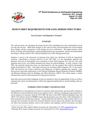
5. Story Drift Limitations
The 1997 UBC requires that story drift be limited to 0.025 for short period structures and 0.020 for long
period structures; these or similar limits have been in place since the 1976 UBC. ASCE 7-02 requires that
story drift be limited based on the type and use of the structure. The intent of both codes was to limit the
interstory drift to a reasonable value, beyond which it was thought that the structure might experience loss
of vertical stability. The UBC also allows these limits to be exceeded, provided that the greater drift can
be tolerated by both structural elements and nonstructural elements that could affect life-safety. For the
UBC, it is not clear why there are two limits on drift, one for short-period structures and one for long-
period structures. In fact, since shorter period structures can have difficulty escaping from the constant
acceleration region of the response spectrum, it could be argued that the prescriptive drift limits should be
reversed, with longer period structures allowed larger drift limits.
It is also not entirely clear why drift limits are required at all; if a designer properly designs a structure to
withstand the maximum expected deflections and still maintain vertical and lateral stability, then a
prescribed limit to interstory drift should not be needed. However, according to the 1975 Blue Book
(SEAOC, 1975), drift limits were added in the 1976 UBC to “insure structural integrity and to restrict
damage to such fragile non-structural elements as glass, plaster walls, etc.” While current codes require
that nonstructural elements be designed to accommodate the maximum expected movement of the
structure, the larger the interstory drifts, the more difficult it becomes to properly design and detail
nonstructural elements such as cladding, windows, and stairs, which are all affected by interstory drifts.
Consequently, it appears that requiring that drift be limited to certain maximum values is reasonable from
a damage control and falling hazard perspective.
Controversy Surrounding Equation 30-7
There has been significant debate and controversy surrounding UBC Equation 30-7. In the published
version of the 1997 UBC, two minimum base shear equations are present (Equations 30-6 and 30-7), only
one of which (Equation 30-6) is exempted from drift calculations. According to a three-page position
paper published by SEAOC (Bachman et al., 2001), SEAOC had also originally agreed to exempt
Equation 30-7 from the drift requirements. However, due to an error, the published version of the UBC
failed to exempt Equation 30-7. Out of a growing concern for near-field pulse effects on long-period
structures, SEAOC then reversed its position and decided to support the use of Equation 30-7 in the UBC.
Around this time, ICBO, the publisher of the UBC, realized that Equation 30-7 had not been exempted
from the drift equations and issued an erratum that exempted Equation 30-7 from the drift limits. SEAOC
then issued the three-page position statement that endorsed the use of Equation 30-7 for both near-fault
and non-near-fault structures. However, the justification for this position statement was a comparison of a
few extremely large, near-field earthquake response spectra with the non-near-field, Soil Type C design
spectrum. The position statement concluded that since the large, near-field earthquake response spectra
exceeded the non-near-field, Soil Type C design response spectrum, the use of Equation 30-7 for drift
calculations was needed to control drift. However, the comparison and the conclusions were arguably
flawed, since the near-field records should have been compared with a near-field response spectrum with
Soil Type D, which would have increased the design spectrum size in the longer periods by a factor of
more than two. Figure 1 shows the response spectra from the five earthquake records that were used in
the SEAOC position paper and compares these spectra with several code design spectra.
6. T=0.5 T=1.0 T=1.5
2.6 T=2.0
Imperial Valley EQ - El C entro VI (1979)
2.4 Imperial Valley EQ - El C entro VII (1979)
Landers EQ - Lucerne N90E (1992)
2.2
N orthridge EQ - Sylmar Converter (1994)
2.0 Tabas EQ - Transverse (1978)
Spectral Acceleration, Sa (g)
1997 UBC R.S., Soil D, Na = 1.5, Nv = 2.0, R = 1
1.8
1997 UBC Equation 30-7, Nv = 2.0, R= 1, 80% M.P.
1.6 1997 UBC R.S. * 1.5, Soil D, Na - 1.5, Nv = 2.0, R = 1
1997 UBC R.S. * 1.5 with Const. Disp. at 5.0 Seconds
1.4
1997 UBC Equation 30-7 * 1.5, N v = 2.0, R = 1, 80% M.P.
1.2 T=3.0
1.0
0.8
T=4.0
0.6
0.4 T=5.0
0.2 T=7.5
T=10
0.0
0 10 20 30 40 50 60 70 80 90 100
Spectral Displacem ent, S d (in)
Figure 1. Comparison of five near-field earthquakes with the UBC near-field response design
spectrum.
Compared to the 1997 UBC response spectra with Soil Type D, NV = 2.0, and an R of 1.0, the actual
earthquake response spectra exceed the design response spectrum in all three portions of the design
response spectrum (i.e. constant acceleration, constant velocity, and constant displacement), which
provides no specific impetus for a minimum base shear equation to address the constant displacement
region of the spectrum alone. Furthermore, when the earthquake response spectra are compared against
the equivalent of the Maximum Considered Design Earthquake (1.5 times the 1997 UBC design response
spectrum), the earthquakes are essentially contained within the design envelope. Assuming that the
response spectrum from the 1978 Tabas earthquake is actually accurate in the long period regions, it could
be argued that the constant displacement cut-off should start at 5.0 seconds instead of 4.0 seconds. Either
way, it is clear from the figure below that the minimum base shear from Equation 30-7 (assuming Soil
Type D, an R of 1.0, and 80% mass participation) greatly over-shoots any demands from these near-field
earthquakes. If adjusted for the MCE event (by multiplying the demand by 1.5), the disparities between
Equation 30-7 and real earthquake demands becomes even larger. Thus, consideration of minimum base
shears in computing deflections does not appear justified at this point.
APPLICATION OF THE CODE IN REAL LIFE
The drift provisions in the 1997 UBC and ASCE 7-02 are fairly complicated. Implementation of these
provisions has significant benefits and yet poses substantial difficulties to designers.
7. Benefits
Assuming that the drift provisions in the UBC and ASCE 7-02 can indeed be followed, the benefits of
successfully implementing the provisions can be substantial.
If properly designed, structural framing elements and connections not part of the lateral force resisting
system should remain largely intact and be able to provide vertical support for the structure even at large
deflections. This eliminates non-ductile failure of vertical load resisting system, such as that seen by some
parking garages during the 1994 Northridge Earthquake.
Non-structural exterior elements will remain largely undamaged by earthquake ground motion. This will
help prevent falling hazard and will limit water intrusion after an earthquake.
Finally, if the drift provisions in current codes are followed buildings should generally not pound together,
which should reduce the threat to the vertical stability of columns from impact from adjacent structures’
non-co-planar floor diaphragms and should eliminate localized pounding damage at co-planar diaphragm
locations.
Difficulties
Recent studies (Freeman and Searer, 2000) have found that the drift provisions in the 1997 UBC are
extremely complicated, are fairly difficult to use, and may be overconservative. Furthermore, it has been
shown that improper application of the provisions can result in significant additional overconservatism in
the design of structural and nonstructural elements.
It can be very difficult to ensure that exterior elements conform to the drift requirements in current codes
(SEAOC, 1999). For a 13-foot story height, design interstory drifts can be as large as approximately 4-
inches in any direction. If slotted holes are to be provided to allow this drift, the slots would need to be in
excess of 8-inches long. By the time construction tolerances are accounted for, the required slots would
need to be 9- or 10-inches long. Claddings with articulations (corners) have proven extremely difficult to
isolate from lateral movements, since slotted holes generally only work for planar cladding elements.
Even if a cladding manufacturer can design a cladding that conforms to the drift requirements, improper
construction can quickly negate that effort (Searer and Freeman, 2004).
Windows can be substantially more difficult to assess. Current technology is often not adequate to
accommodate racking on the order of 4-inches in each direction (for a 13-foot story). Even if a window
manufacturer can provide calculations that show that a cladding will accommodate drifts on the order of
2.5 percent, use of shims and blocks during actual installation of the windows can often preclude
movement from occurring.
In order to conform to the drift requirements, sealant joints (between cladding elements or between
various portions of structures) can become extremely large, which can have adverse effects on the
performance of waterproofing for the structures.
Finally, it is not entirely clear how the most common type of all structures in the United States -- the
wood-frame structure -- should be designed with respect to drift requirements. In general, the standard of
practice for wood-frame designers has been to ignore the code drift requirements for wood-framed
residential structures, which have substantial nonlinear behavior at even low loads, and which are
generally designed without the use of computer models.
8. RECOMMENDATIONS
Based on the above discussion, it appears that a more restrictive drift limit for longer-period structures as
is currently the case in the 1997 UBC is unwarranted, since low-rise and mid-rise structures have
historically performed far worse in the U.S. than modern high-rises. In a study of sixteen different
structures (Freeman and Searer, 2000), the structure that had the greatest drift demands and would
arguably be the most likely to collapse during a large earthquake was the 3-story steel moment frame and
not the high-rises that were analyzed. In fact, conventional structural engineering wisdom dictates that the
best place to be in a major earthquake (other than an open field or possibly in a base-isolated structure) is
in a high-rise. This confidence in tall, long-period structures is due to the ability of the longer-period
structures to accommodate relatively large displacement demands with relatively small displacements on
each floor. For example, if a 50-story structure experiences 1.5-inches of displacement per floor (only 1%
story drift assuming 13-foot high stories), that displacement equates to a 50-inch spectral displacement
demand. If the same structure can withstand say twice that amount, i.e. 2% story drift, that equates to a
spectral displacement capacity of 100-inches, more than sufficient to ride out even the largest recorded
earthquakes, possibly without even experiencing inelastic behavior. Finally, as stated earlier, since shorter
period structures can have difficulty escaping from the constant acceleration region of the response
spectrum, it appears that reversal of the 1997 UBC prescriptive drift limits may be warranted, with
shorter-period structures allowed smaller drift limits and longer-period structures allowed larger drift
limits. By increasing the stiffness of low-rise structures, the strength of these structures is generally
increased, and ductility demands on these structures as they struggle to escape the constant acceleration
region of the response spectrum are generally decreased.
Some building codes limit interstory drift to much smaller values. For example, in Peru, drift is limited to
0.7% for reinforced concrete structures, 1.0% for steel structures, 0.5% for masonry structures, and 1.0%
for wood structures, based on the full, unreduced earthquake demand (National Construction Code, Peru,
1997). Consequently, drift requirements are generally accomplished by the addition of reinforced
concrete or confined masonry shear walls. There are definite advantages to using a strong and stiff lateral
system, such as reinforced concrete shear walls, since structural damage can be limited to cracking and
spalling of the shear walls, which protects the vertical load resisting elements from significant damage.
Damage to nonstructural elements such as partitions, walls, cladding, and windows will be similarly
limited. Floor accelerations would be increased, which could increase damage to certain other
nonstructural elements and equipment unless they were also designed and constructed for larger forces. If
U.S. public policy makers or code development agencies one day decide that reduction of damage and
economic loss due to earthquakes is a significant priority, reducing the allowable story drift for short
period structures and requiring a corresponding increase in design force requirements for nonstructural
elements might be a fairly simple way to accomplish this. However, it is important that artificial limits
and minimum base shears for the calculation of displacement be eliminated, so that the best
approximations of displacement and drift can be obtained.
REFERENCES
1. Applied Technology Council, Tentative Provisions for the Development of Seismic Regulations for
Buildings, Washington, D.C., 1978
2. Bachman, Robert E., Hamburger, Ronald O., and Kircher, Charles, “Seismology Committee
Background and Position Regarding 1997 UBC Eq. 30-7 and Drift”, Structural Engineers
Association of California, September, 2001.
3. Earthquake Engineering Research Institute, “Slides on the January 17, 1994, Northridge
Earthquake”, Oakland, California, 1994.
9. 4. Freeman, Sigmund A. and Searer, Gary R., “Impact of the Revised Earthquake Drift Provisions On
Design and Construction”, 2000 Structural Engineers Association of California Convention,
August, 2000.
5. International Conference of Building Officials, Uniform Building Code, 1961 Edition, Los Angeles,
California, 1961.
6. International Conference of Building Officials, Uniform Building Code, 1967 Edition, Pasadena,
California, 1967.
7. International Conference of Building Officials, Uniform Building Code, 1973 Edition, Whittier,
California, 1973.
8. International Conference of Building Officials, Uniform Building Code, 1976 Edition, Whittier,
California, 1976.
9. International Conference of Building Officials, Uniform Building Code, 1988 Edition, Whittier,
California, 1988.
10. International Conference of Building Officials, 1997 Uniform Building Code, Whittier, California,
1997.
11. National Construction Code, Technical Standard for Buildings, E.030, Earthquake Resistant
Design, Lima, Peru, 1997, translated by Fierro, Eduardo A. and Perry, Cynthia, L.
12. Searer, Gary R. and Freeman, Sigmund, A., “Seismic Drift and the Design of Claddings,”
Proceedings of the ASCE Structures Congress and Exposition, 2004.
13. Structural Engineers Association of California, Recommended Lateral Force Requirements and
Commentary, San Francisco, California, 1975.
14. Structural Engineers Association of California, Recommended Lateral Force Requirements and
Commentary, Sacramento, California, 1999.