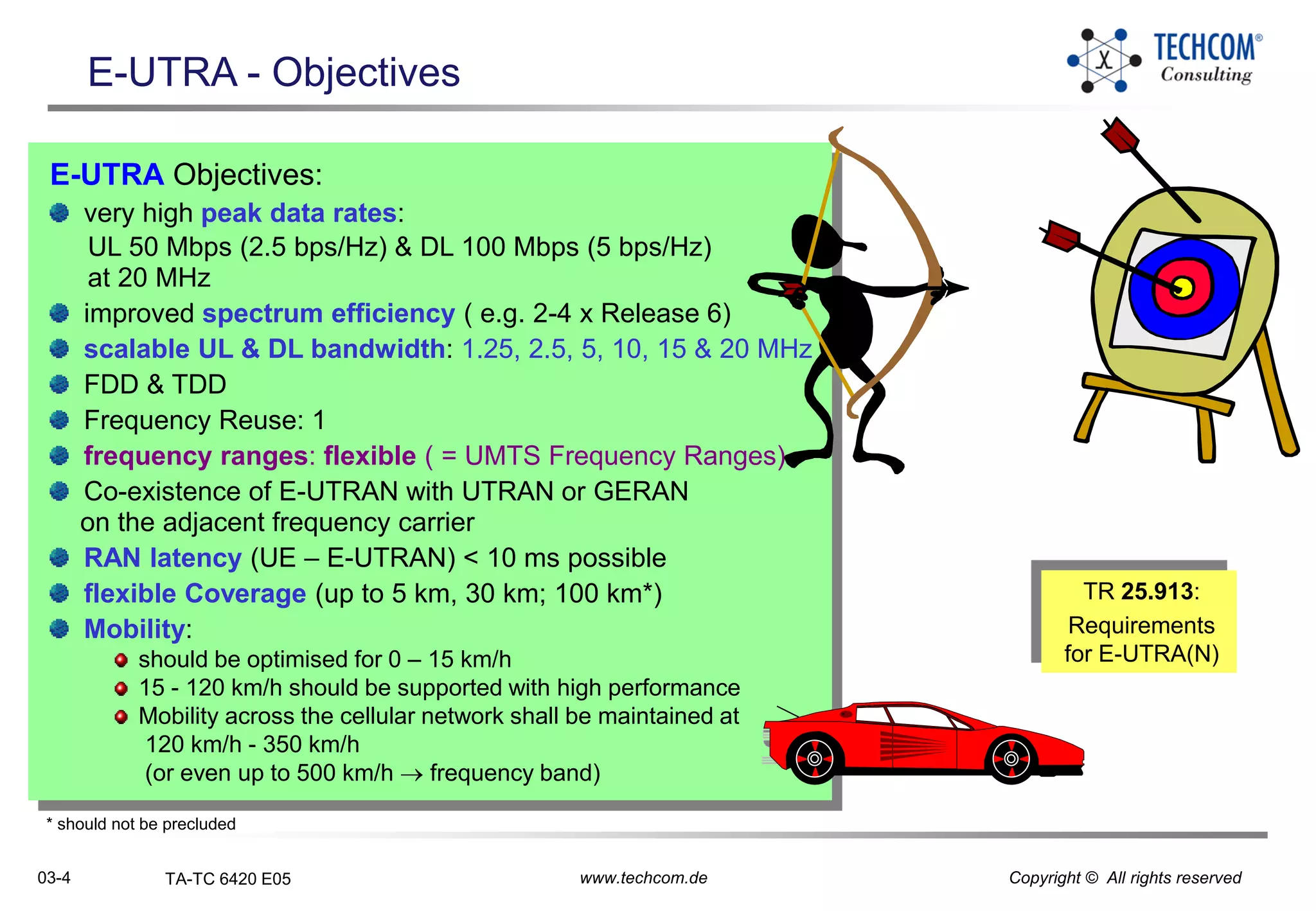
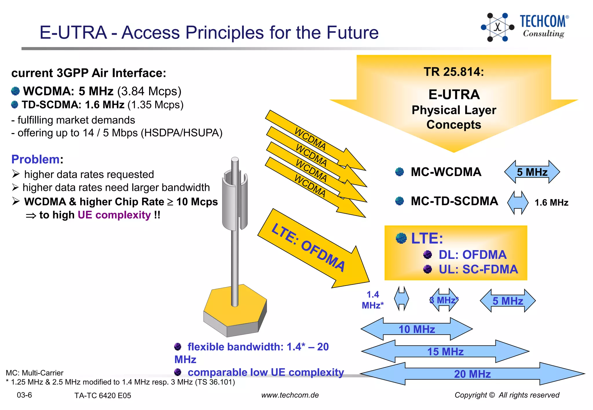
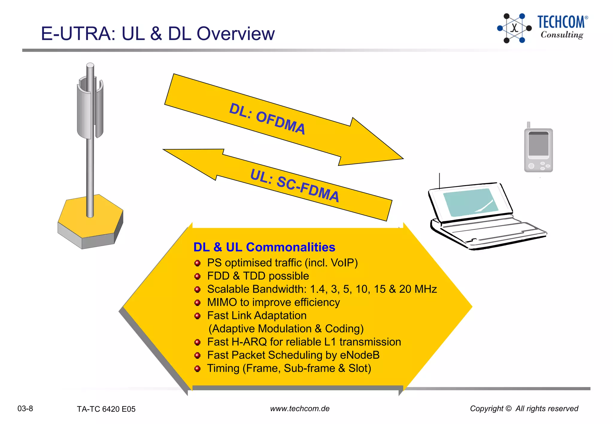
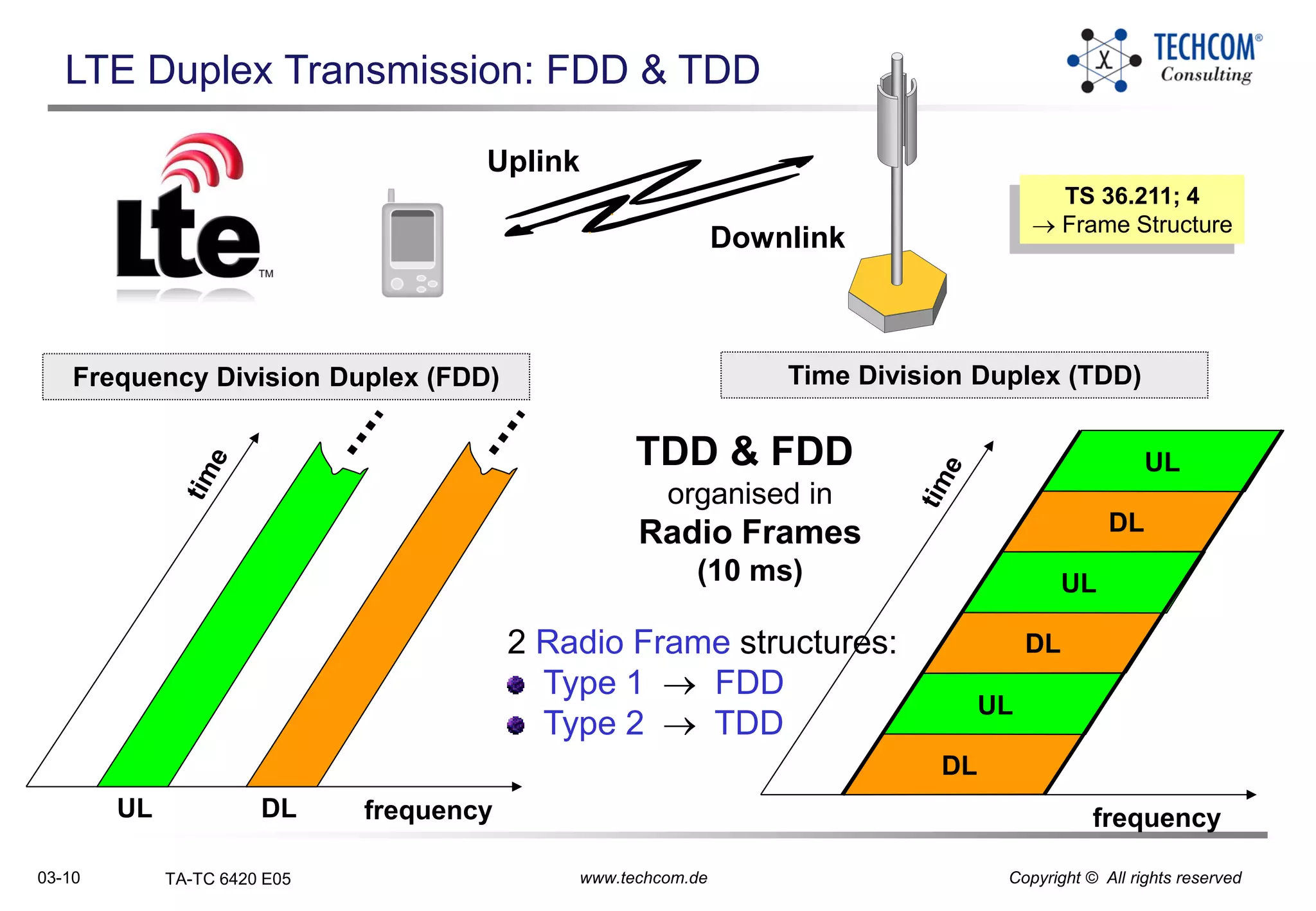
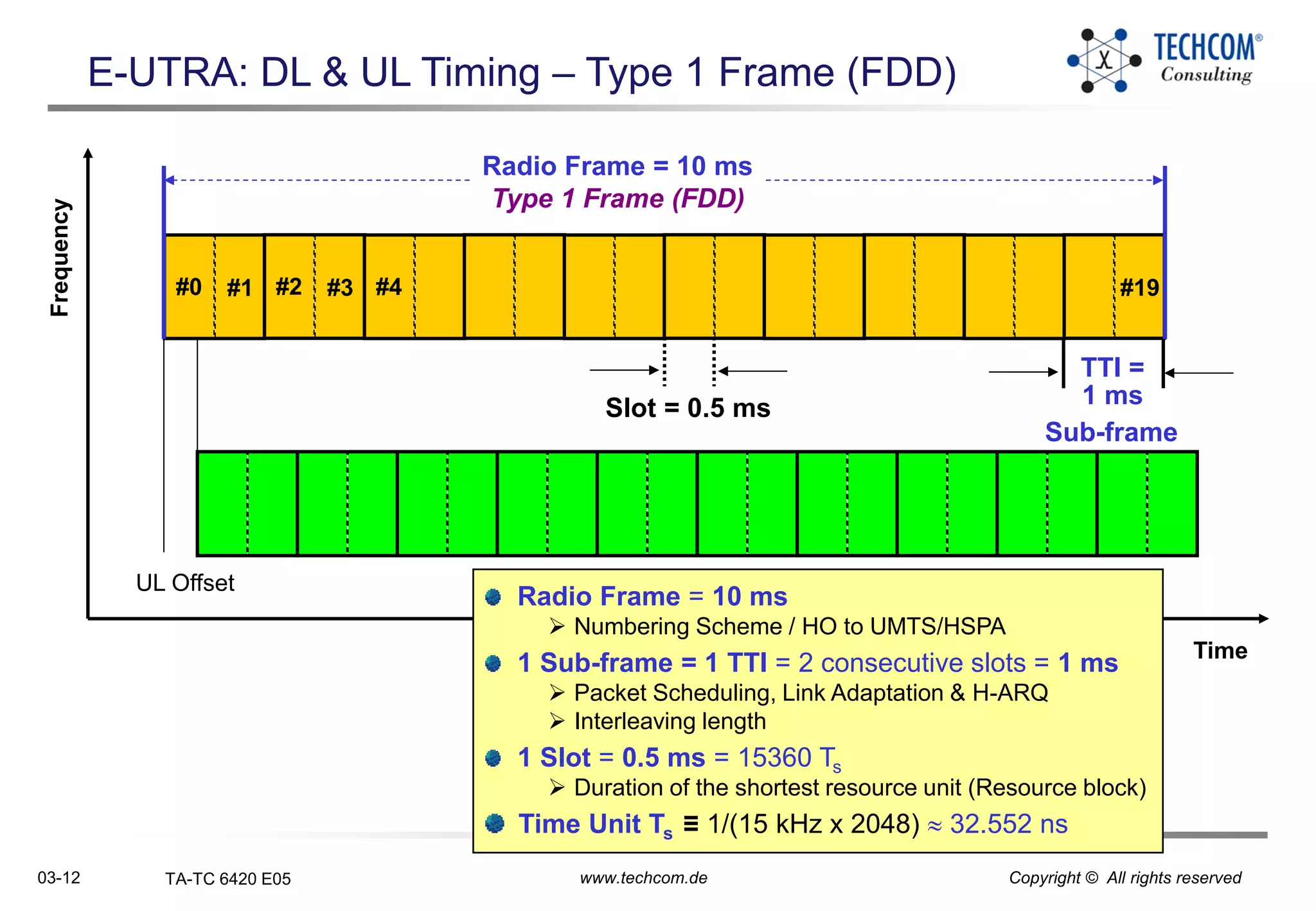
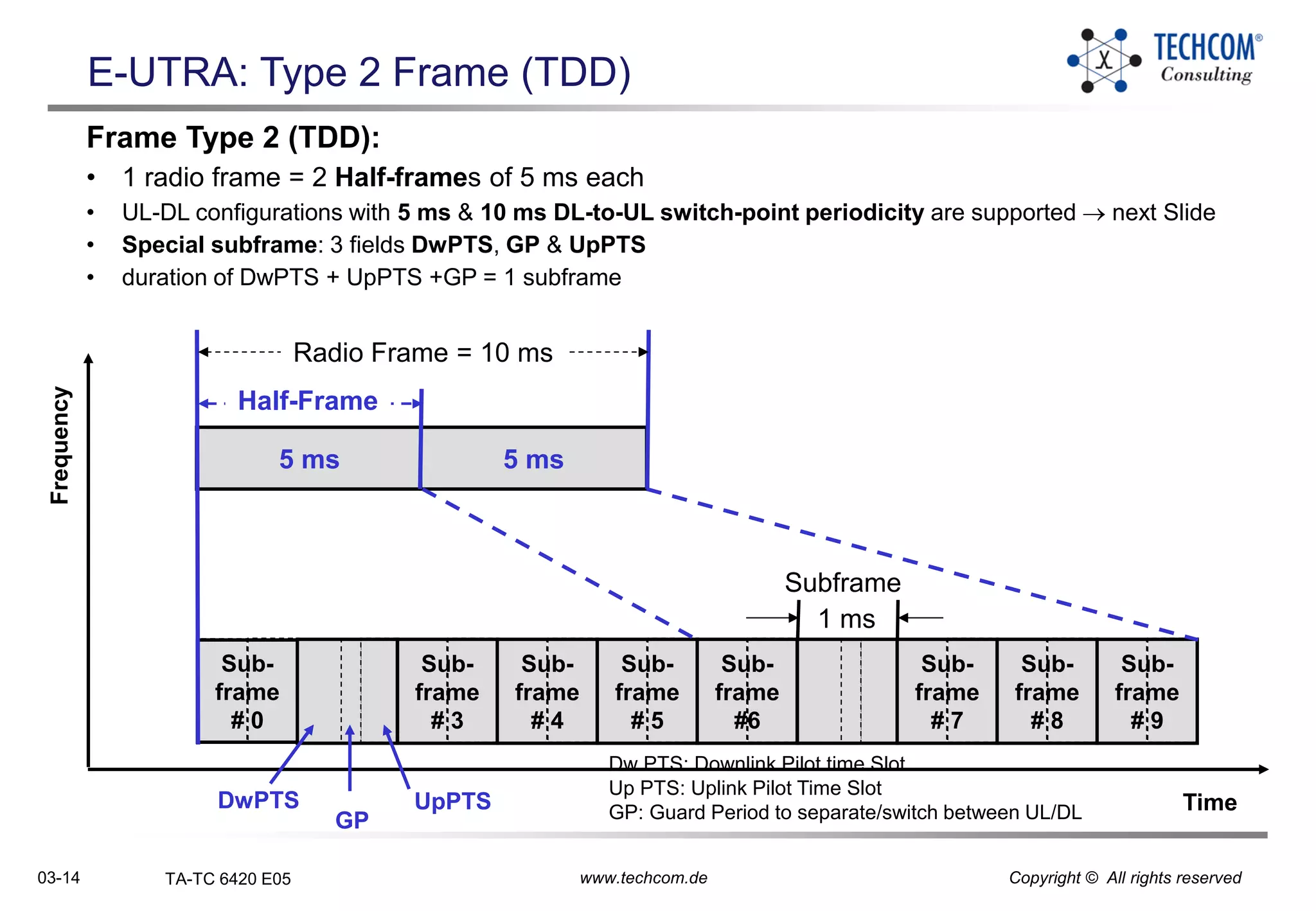
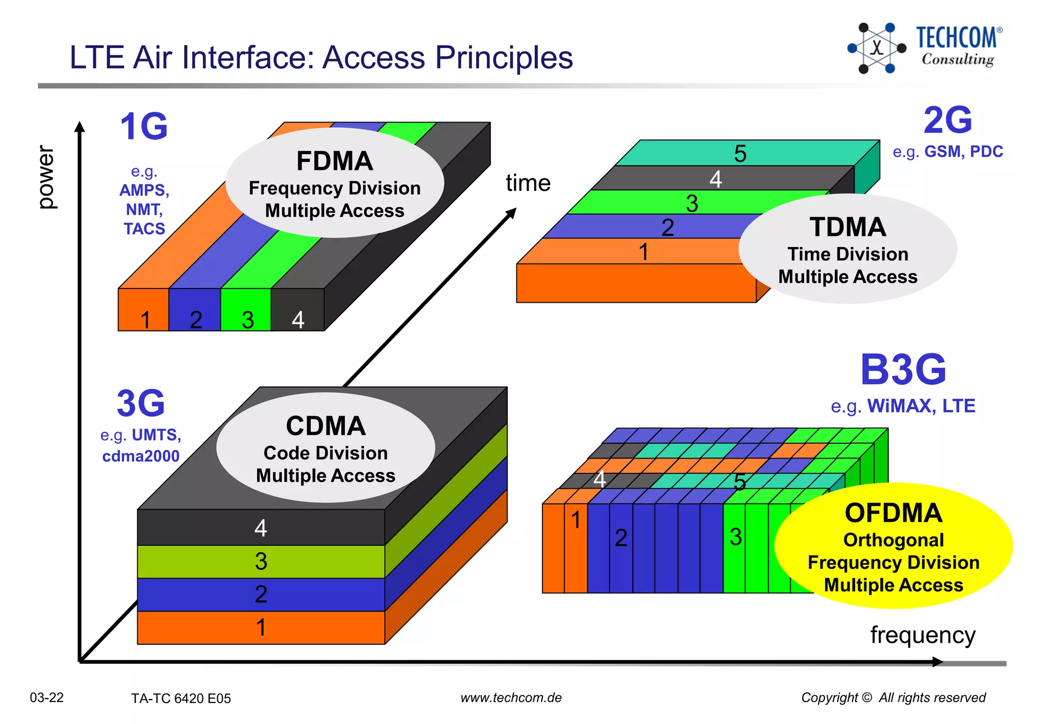
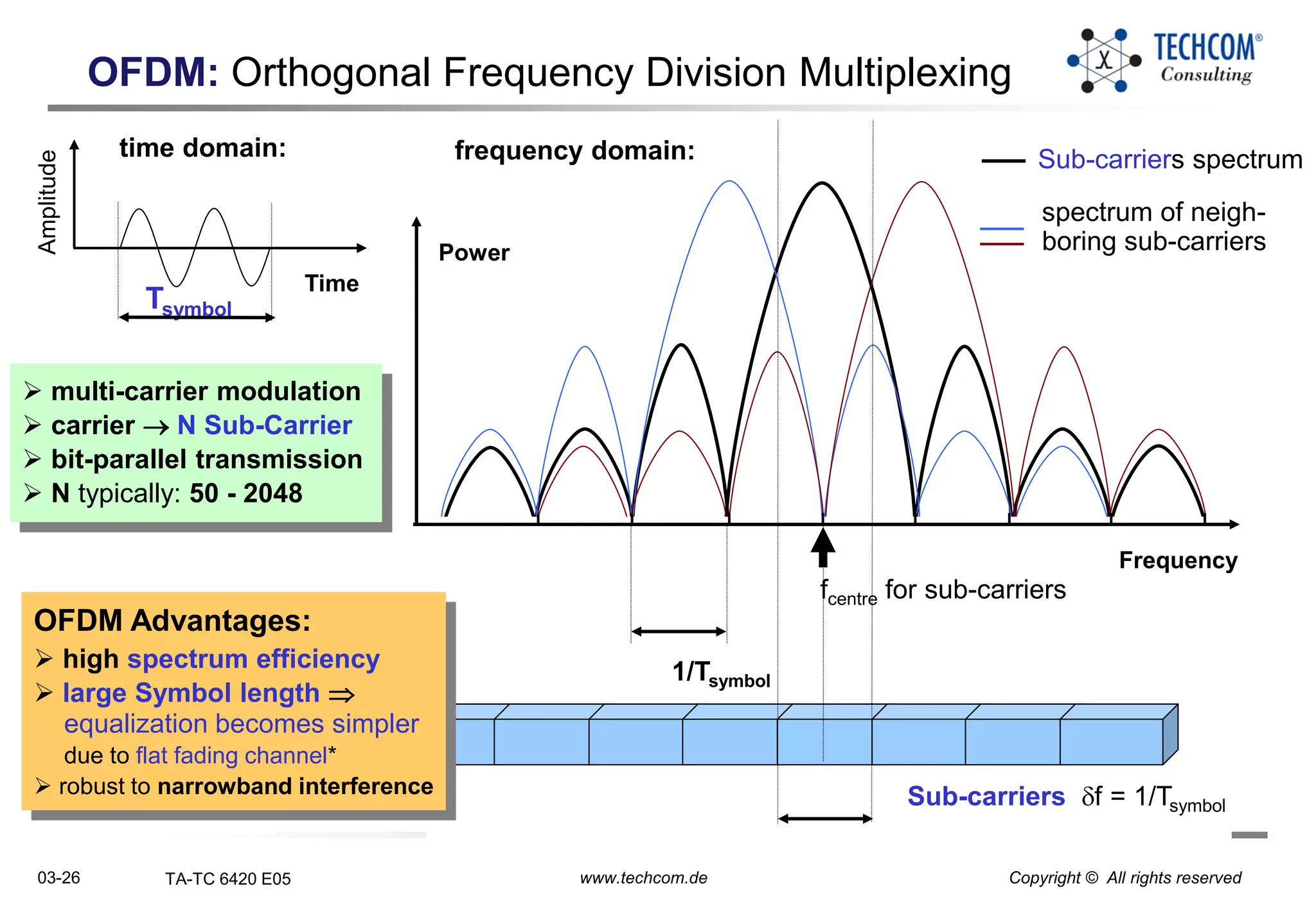
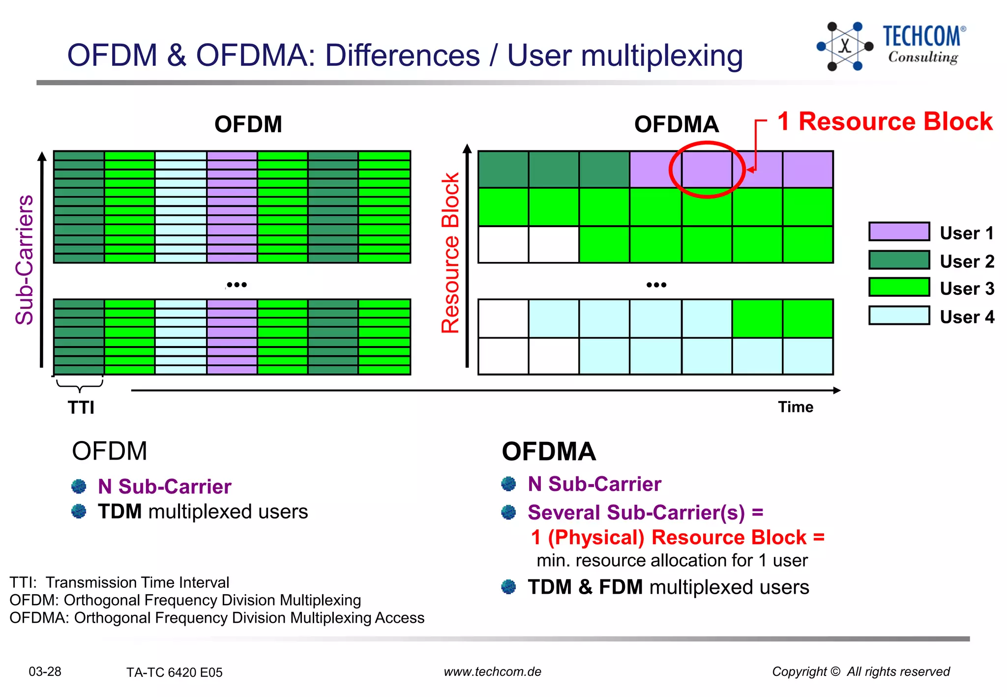
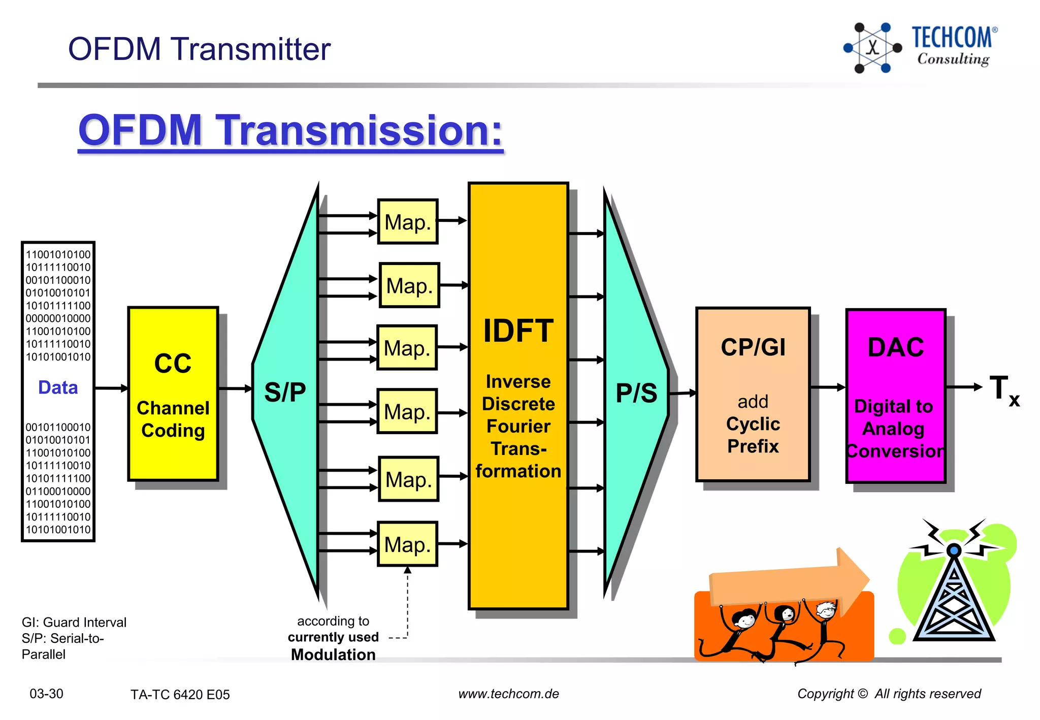
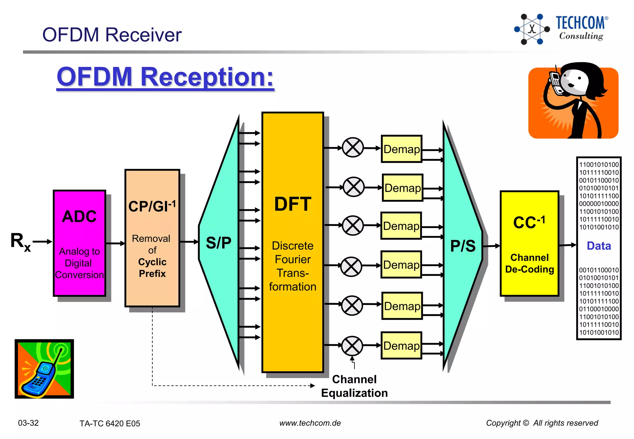
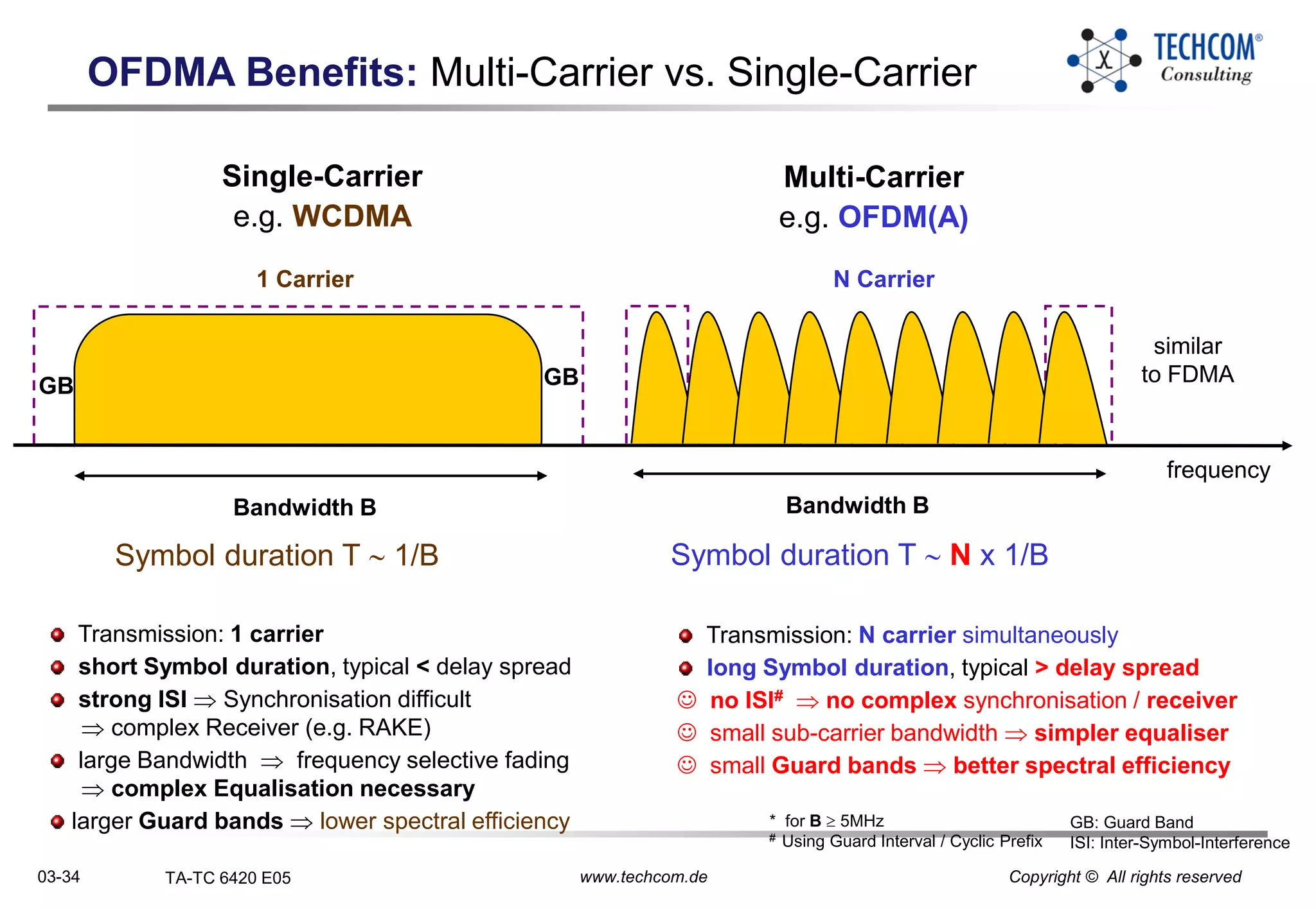
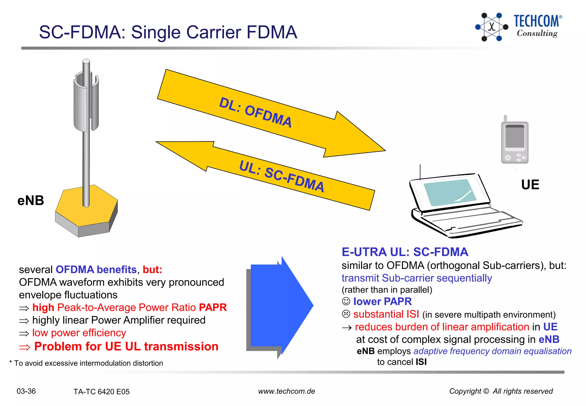
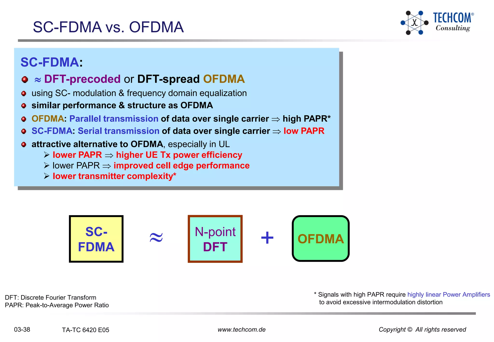
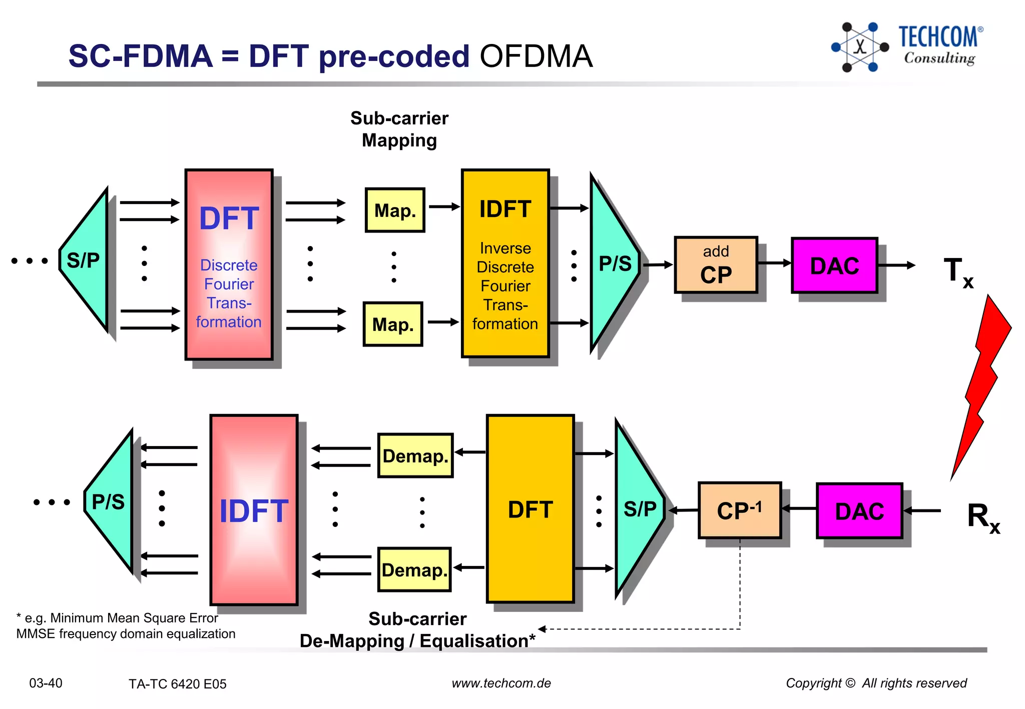
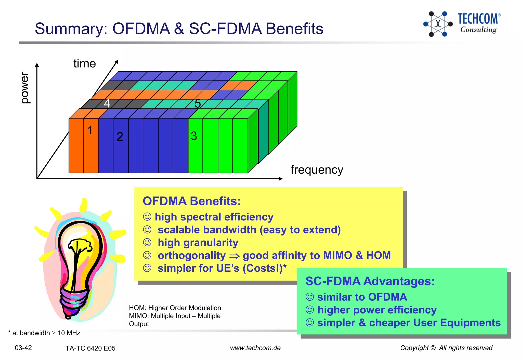
03-1 TA-TC 6420 E05 www.techcom.de Copyright © All rights reserved
Contents
LTE Radio Network Planning
 Network Architecture and Interfaces
 LTE Radio Interface Protocols
 E-UTRA Layer 1 Key Aspects and OFDM(A) Principles
 E-UTRA Transmission OFDMA and SC-FDMA
 LTE and MIMO
 LTE Physical Layer Channels and Procedures
 Physical Layer Overhead
 LTE Frequencies
 Link Budget
 LTE Capacity Calculation
 VoLTE
 LTE Advanced
 PCI, PRACH and Paging
 Literature and Abbreviations
03-3 TA-TC 6420 E05 www.techcom.de Copyright © All rights reserved
Content
E-UTRA
UE
eNode B
E-UTRA Layer 1 Key Aspects and OFDM(A) Principles
 E-UTRA Layer 1 Key Aspects
 OFDM(A) and SC-FDMA Principles
03-4 TA-TC 6420 E05 www.techcom.de Copyright © All rights reserved
E-UTRA Objectives:
very high peak data rates:
UL 50 Mbps (2.5 bps/Hz) & DL 100 Mbps (5 bps/Hz)
at 20 MHz
improved spectrum efficiency ( e.g. 2-4 x Release 6)
scalable UL & DL bandwidth: 1.25, 2.5, 5, 10, 15 & 20 MHz
FDD & TDD
Frequency Reuse: 1
frequency ranges: flexible ( = UMTS Frequency Ranges)
Co-existence of E-UTRAN with UTRAN or GERAN
on the adjacent frequency carrier
RAN latency (UE – E-UTRAN) < 10 ms possible
flexible Coverage (up to 5 km, 30 km; 100 km*)
Mobility:
should be optimised for 0 – 15 km/h
15 - 120 km/h should be supported with high performance
Mobility across the cellular network shall be maintained at
120 km/h - 350 km/h
(or even up to 500 km/h  frequency band)
E-UTRA - Objectives
TR 25.913:
Requirements
for E-UTRA(N)
* should not be precluded
03-6 TA-TC 6420 E05 www.techcom.de Copyright © All rights reserved
TR 25.814:
E-UTRA
Physical Layer
Concepts
current 3GPP Air Interface:
WCDMA: 5 MHz (3.84 Mcps)
TD-SCDMA: 1.6 MHz (1.35 Mcps)
- fulfilling market demands
- offering up to 14 / 5 Mbps (HSDPA/HSUPA)
Problem:
 higher data rates requested
 higher data rates need larger bandwidth
 WCDMA & higher Chip Rate  10 Mcps
 to high UE complexity !!
MC-WCDMA
MC-TD-SCDMA
E-UTRA - Access Principles for the Future
LTE:
DL: OFDMA
UL: SC-FDMA
5 MHz
1.6 MHz
3 MHz* 5 MHz
10 MHz
15 MHz
20 MHz
1.4
MHz*
flexible bandwidth: 1.4* – 20
MHz
comparable low UE complexityMC: Multi-Carrier
* 1.25 MHz & 2.5 MHz modified to 1.4 MHz resp. 3 MHz (TS 36.101)
03-8 TA-TC 6420 E05 www.techcom.de Copyright © All rights reserved
E-UTRA: UL & DL Overview
DL & UL Commonalities
PS optimised traffic (incl. VoIP)
FDD & TDD possible
Scalable Bandwidth: 1.4, 3, 5, 10, 15 & 20 MHz
MIMO to improve efficiency
Fast Link Adaptation
(Adaptive Modulation & Coding)
Fast H-ARQ for reliable L1 transmission
Fast Packet Scheduling by eNodeB
Timing (Frame, Sub-frame & Slot)
03-10 TA-TC 6420 E05 www.techcom.de Copyright © All rights reserved
LTE Duplex Transmission: FDD & TDD
frequencyDLUL
UL
frequency
Frequency Division Duplex (FDD) Time Division Duplex (TDD)
Uplink
Downlink
DL
UL
DL
UL
DL
TDD & FDD
organised in
Radio Frames
(10 ms)
2 Radio Frame structures:
Type 1  FDD
Type 2  TDD
TS 36.211; 4
 Frame Structure
03-12 TA-TC 6420 E05 www.techcom.de Copyright © All rights reserved
E-UTRA: DL & UL Timing – Type 1 Frame (FDD)Frequency
Time
#0 #1 #2 #3 #4 #19
Radio Frame = 10 ms
Type 1 Frame (FDD)
TTI =
1 msSlot = 0.5 ms
UL Offset
Radio Frame = 10 ms
 Numbering Scheme / HO to UMTS/HSPA
1 Sub-frame = 1 TTI = 2 consecutive slots = 1 ms
 Packet Scheduling, Link Adaptation & H-ARQ
 Interleaving length
1 Slot = 0.5 ms = 15360 Ts
 Duration of the shortest resource unit (Resource block)
Time Unit Ts ≡ 1/(15 kHz x 2048)  32.552 ns
Sub-frame
03-14 TA-TC 6420 E05 www.techcom.de Copyright © All rights reserved
E-UTRA: Type 2 Frame (TDD)
Frame Type 2 (TDD):
• 1 radio frame = 2 Half-frames of 5 ms each
• UL-DL configurations with 5 ms & 10 ms DL-to-UL switch-point periodicity are supported  next Slide
• Special subframe: 3 fields DwPTS, GP & UpPTS
• duration of DwPTS + UpPTS +GP = 1 subframe
Frequency
Time
Sub-
frame
# 0
Sub-
frame
# 3
Sub-
frame
# 4
Sub-
frame
# 5
Sub-
frame
#6
Sub-
frame
# 7
Sub-
frame
# 8
Sub-
frame
# 9
5 ms 5 ms
Radio Frame = 10 ms
Half-Frame
1 ms
Subframe
Dw PTS: Downlink Pilot time Slot
Up PTS: Uplink Pilot Time Slot
GP: Guard Period to separate/switch between UL/DL
DwPTS UpPTS
GP
03-16 TA-TC 6420 E05 www.techcom.de Copyright © All rights reserved
E-UTRA: Type 2 Frame (TDD)
7 frame configurations  different DL/UL partition
DL / UL ratio can vary from 1/3 (Config. 0) to 8/1 (Config. 5)  service requirements of the carrier
1 frame = 10 ms
1 subframe = 1 ms
DL
DL
DL
DL
DL
DL
DL
DL
DLDL
DL DLDL
DL DL DL DL DL
DL
DLDL
DL
DL
DL
DL
DL
DL
DL
DL
DL
DL
DL
DL
DL
DLDL
UL
UL
UL
UL
UL
UL
UL UL UL UL UL
ULUL
UL
UL
UL
UL
UL
UL
UL
UL
UL
UL
SS
SS
SS
SS
SS
SS
SS
SS
SS
SS
SS
0
1
2
3
4
5
6
DL – Downlink subframe
UL – Uplink subframe
SS – Special Switching subframe
always for DL transmission
UpPTS & subframe following the special
subframe always reserved for UL transmission
03-18 TA-TC 6420 E05 www.techcom.de Copyright © All rights reserved
Type 2 Frame (TDD): Special Subframe
UL
eNB
UE
PT PTSP
eNodeB stops
transmission
End of DL subframe
received by UE
UE switches to transmission
of UL subframe
Start of UL subframe
received by eNodeB
PT = Propagation Time
SP = Switching Period
RTD = Round Trip Delay
GP = Guard Period
RTD = 2 x PT
GP = RTD + SP
TS 36.211; Tab. 4.2-1:
Configuration of special subframe
(duration of Dw PTS/GP/Up PTS)
GP: Guard Period
• needed to switch from Rx to Tx
• includes RTD (Round Trip Delay).
Special
Subframe
Dw
PTS
Up
PTS
GP
Sub-
frame
#0
Sub-
frame
#3
GP
DL
DL UL
DwPTS: DL Pilot time Slot
UpPTS: UL Pilot Time Slot
• reduced UL & DL transmission duration
• DL used e.g. for L1 Control information
(PDCCH with max. 2 OFDM symbol)
• UL only for shortened random access
(small cells only) & UL Reference Signals
03-22 TA-TC 6420 E05 www.techcom.de Copyright © All rights reserved
LTE Air Interface: Access Principles
1 2 3 4
1
2
3
4
5FDMA
Frequency Division
Multiple Access
frequency
1G 2G
e.g. GSM, PDC
2G: TDMA
1
2
3
4
e.g.
AMPS,
NMT,
TACS
time
CDMA
Code Division
Multiple Access
TDMA
Time Division
Multiple Access
3G
e.g. UMTS,
cdma2000
power
1
2 3
4 5
B3G
e.g. WiMAX, LTE
OFDMA
Orthogonal
Frequency Division
Multiple Access
03-24 TA-TC 6420 E05 www.techcom.de Copyright © All rights reserved
OFDM(A) History
1966: Chang, Bell Labs: OFDM paper + patent
1971: Weinstein & Ebert: propose use of FFT & Guard Interval
1985: Cimini:use of OFDM for mobile communications
1987: Alard& Lasalle: OFDM for digital broadcasting
1995: ETSI DAB standard: first OFDM based standard
1997: ETSI DVB-T standard
1999: IEEE 802.11a WLAN standard
2000: Flash-OFDM for BWA
2002: IEEE 802.11g
2004: IEEE 802.16-2004 (Fixed WiMAX)
2004: IEEE 802.15.3a (Wireless PAN)
2005: IEEE 802.16-2005 (Mobile WiMAX)
2007: IEEE 802.11n WLAN
2008: 3GPP / LTE
2010 & beyond:
- IEEE 802.16m (“Gigabyte” WiMAX)
- LTE-Advanced (LTE-A)
N carriers
Bandwidth
B
4G-Candidates (IMT-Advanced)
03-26 TA-TC 6420 E05 www.techcom.de Copyright © All rights reserved
OFDM: Orthogonal Frequency Division Multiplexing
spectrum of neigh-
boring sub-carriersPower
Frequency
1/Tsymbol
fcentre for sub-carriers
Sub-carriers df = 1/Tsymbol
Sub-carriers spectrumfrequency domain:
 multi-carrier modulation
 carrier  N Sub-Carrier
 bit-parallel transmission
 N typically: 50 - 2048
Amplitude
Time
Tsymbol
time domain:
OFDM Advantages:
 high spectrum efficiency
 large Symbol length 
equalization becomes simpler
due to flat fading channel*
 robust to narrowband interference
03-28 TA-TC 6420 E05 www.techcom.de Copyright © All rights reserved
OFDM & OFDMA: Differences / User multiplexing
802.16e:
SOFDMA
(very complex)
OFDMAOFDM
Sub-Carriers
TTI Time
ResourceBlock
User 1
User 2
User 3
User 4
••• •••
TTI: Transmission Time Interval
OFDM: Orthogonal Frequency Division Multiplexing
OFDMA: Orthogonal Frequency Division Multiplexing Access
OFDM
N Sub-Carrier
TDM multiplexed users
OFDMA
N Sub-Carrier
Several Sub-Carrier(s) =
1 (Physical) Resource Block =
min. resource allocation for 1 user
TDM & FDM multiplexed users
1 Resource Block
03-30 TA-TC 6420 E05 www.techcom.de Copyright © All rights reserved
OFDM Transmitter
11001010100
10111110010
00101100010
01010010101
10101111100
00000010000
11001010100
10111110010
10101001010
Data
00101100010
01010010101
11001010100
10111110010
10101111100
01100010000
11001010100
10111110010
10101001010
CC
Channel
Coding
S/P
Map.
Map.
Map.
Map.
Map.
Map.
IDFT
Inverse
Discrete
Fourier
Trans-
formation
CP/GI
add
Cyclic
Prefix
DAC
Digital to
Analog
Conversion
Tx
OFDM Transmission:
GI: Guard Interval
S/P: Serial-to-
Parallel
according to
currently used
Modulation
03-32 TA-TC 6420 E05 www.techcom.de Copyright © All rights reserved
OFDM Reception:
11001010100
10111110010
00101100010
01010010101
10101111100
00000010000
11001010100
10111110010
10101001010
Data
00101100010
01010010101
11001010100
10111110010
10101111100
01100010000
11001010100
10111110010
10101001010
CC-1
Channel
De-Coding
ADC
Analog to
Digital
Conversion
Rx
CP/GI-1
Removal
of
Cyclic
Prefix
Demap
Demap
Demap
Demap
Demap
Demap
DFT
Discrete
Fourier
Trans-
formation
Channel
Equalization
S/P
OFDM Receiver
03-34 TA-TC 6420 E05 www.techcom.de Copyright © All rights reserved
Multi-Carrier
e.g. OFDM(A)
Bandwidth BBandwidth B
Single-Carrier
e.g. WCDMA
OFDMA Benefits: Multi-Carrier vs. Single-Carrier
frequency
Symbol duration T  1/B Symbol duration T  N x 1/B
1 Carrier N Carrier
similar
to FDMA
Transmission: 1 carrier
short Symbol duration, typical < delay spread
strong ISI  Synchronisation difficult
 complex Receiver (e.g. RAKE)
large Bandwidth  frequency selective fading
 complex Equalisation necessary
larger Guard bands  lower spectral efficiency
Transmission: N carrier simultaneously
long Symbol duration, typical > delay spread
 no ISI#  no complex synchronisation / receiver
 small sub-carrier bandwidth  simpler equaliser
 small Guard bands  better spectral efficiency
* for B  5MHz
# Using Guard Interval / Cyclic Prefix
GB: Guard Band
ISI: Inter-Symbol-Interference
GB GB
03-36 TA-TC 6420 E05 www.techcom.de Copyright © All rights reserved
SC-FDMA: Single Carrier FDMA
several OFDMA benefits, but:
OFDMA waveform exhibits very pronounced
envelope fluctuations
 high Peak-to-Average Power Ratio PAPR
 highly linear Power Amplifier required
 low power efficiency
 Problem for UE UL transmission
* To avoid excessive intermodulation distortion
E-UTRA UL: SC-FDMA
similar to OFDMA (orthogonal Sub-carriers), but:
transmit Sub-carrier sequentially
(rather than in parallel)
 lower PAPR
 substantial ISI (in severe multipath environment)
 reduces burden of linear amplification in UE
at cost of complex signal processing in eNB
eNB employs adaptive frequency domain equalisation
to cancel ISI
eNB
UE
03-38 TA-TC 6420 E05 www.techcom.de Copyright © All rights reserved
SC-FDMA vs. OFDMA
SC-FDMA:
 DFT-precoded or DFT-spread OFDMA
using SC- modulation & frequency domain equalization
similar performance & structure as OFDMA
OFDMA: Parallel transmission of data over single carrier  high PAPR*
SC-FDMA: Serial transmission of data over single carrier  low PAPR
attractive alternative to OFDMA, especially in UL
 lower PAPR  higher UE Tx power efficiency
 lower PAPR  improved cell edge performance
 lower transmitter complexity*
DFT: Discrete Fourier Transform
PAPR: Peak-to-Average Power Ratio
* Signals with high PAPR require highly linear Power Amplifiers
to avoid excessive intermodulation distortion
SC-
FDMA
 OFDMA+N-point
DFT
03-40 TA-TC 6420 E05 www.techcom.de Copyright © All rights reserved
SC-FDMA = DFT pre-coded OFDMA
DFT
Discrete
Fourier
Trans-
formation
•
•
•
Map.
Map.
•
•
•
IDFT
Inverse
Discrete
Fourier
Trans-
formation
add
CP DAC Tx
•
•
•
•
•
• IDFT
•
•
•
Demap.
Demap.
•
•
•
DFT CP-1 DAC Rx
•
•
•
Sub-carrier
Mapping
Sub-carrier
De-Mapping / Equalisation*
S/P
•
•
•
P/S
•
•
•
•
•
•
* e.g. Minimum Mean Square Error
MMSE frequency domain equalization
03-42 TA-TC 6420 E05 www.techcom.de Copyright © All rights reserved
Summary: OFDMA & SC-FDMA Benefits
frequency
power
1
2 3
4 5
OFDMA Benefits:
 high spectral efficiency
 scalable bandwidth (easy to extend)
 high granularity
 orthogonality  good affinity to MIMO & HOM
 simpler for UE’s (Costs!)*
* at bandwidth  10 MHz
time
SC-FDMA Advantages:
 similar to OFDMA
 higher power efficiency
 simpler & cheaper User Equipments
HOM: Higher Order Modulation
MIMO: Multiple Input – Multiple
Output

03 6420 e-utra layer 1 key aspects and ofdm(a) principles_e05

  • 1.
    03-1 TA-TC 6420E05 www.techcom.de Copyright © All rights reserved Contents LTE Radio Network Planning  Network Architecture and Interfaces  LTE Radio Interface Protocols  E-UTRA Layer 1 Key Aspects and OFDM(A) Principles  E-UTRA Transmission OFDMA and SC-FDMA  LTE and MIMO  LTE Physical Layer Channels and Procedures  Physical Layer Overhead  LTE Frequencies  Link Budget  LTE Capacity Calculation  VoLTE  LTE Advanced  PCI, PRACH and Paging  Literature and Abbreviations
  • 2.
    03-3 TA-TC 6420E05 www.techcom.de Copyright © All rights reserved Content E-UTRA UE eNode B E-UTRA Layer 1 Key Aspects and OFDM(A) Principles  E-UTRA Layer 1 Key Aspects  OFDM(A) and SC-FDMA Principles
  • 3.
    03-4 TA-TC 6420E05 www.techcom.de Copyright © All rights reserved E-UTRA Objectives: very high peak data rates: UL 50 Mbps (2.5 bps/Hz) & DL 100 Mbps (5 bps/Hz) at 20 MHz improved spectrum efficiency ( e.g. 2-4 x Release 6) scalable UL & DL bandwidth: 1.25, 2.5, 5, 10, 15 & 20 MHz FDD & TDD Frequency Reuse: 1 frequency ranges: flexible ( = UMTS Frequency Ranges) Co-existence of E-UTRAN with UTRAN or GERAN on the adjacent frequency carrier RAN latency (UE – E-UTRAN) < 10 ms possible flexible Coverage (up to 5 km, 30 km; 100 km*) Mobility: should be optimised for 0 – 15 km/h 15 - 120 km/h should be supported with high performance Mobility across the cellular network shall be maintained at 120 km/h - 350 km/h (or even up to 500 km/h  frequency band) E-UTRA - Objectives TR 25.913: Requirements for E-UTRA(N) * should not be precluded
  • 4.
    03-6 TA-TC 6420E05 www.techcom.de Copyright © All rights reserved TR 25.814: E-UTRA Physical Layer Concepts current 3GPP Air Interface: WCDMA: 5 MHz (3.84 Mcps) TD-SCDMA: 1.6 MHz (1.35 Mcps) - fulfilling market demands - offering up to 14 / 5 Mbps (HSDPA/HSUPA) Problem:  higher data rates requested  higher data rates need larger bandwidth  WCDMA & higher Chip Rate  10 Mcps  to high UE complexity !! MC-WCDMA MC-TD-SCDMA E-UTRA - Access Principles for the Future LTE: DL: OFDMA UL: SC-FDMA 5 MHz 1.6 MHz 3 MHz* 5 MHz 10 MHz 15 MHz 20 MHz 1.4 MHz* flexible bandwidth: 1.4* – 20 MHz comparable low UE complexityMC: Multi-Carrier * 1.25 MHz & 2.5 MHz modified to 1.4 MHz resp. 3 MHz (TS 36.101)
  • 5.
    03-8 TA-TC 6420E05 www.techcom.de Copyright © All rights reserved E-UTRA: UL & DL Overview DL & UL Commonalities PS optimised traffic (incl. VoIP) FDD & TDD possible Scalable Bandwidth: 1.4, 3, 5, 10, 15 & 20 MHz MIMO to improve efficiency Fast Link Adaptation (Adaptive Modulation & Coding) Fast H-ARQ for reliable L1 transmission Fast Packet Scheduling by eNodeB Timing (Frame, Sub-frame & Slot)
  • 6.
    03-10 TA-TC 6420E05 www.techcom.de Copyright © All rights reserved LTE Duplex Transmission: FDD & TDD frequencyDLUL UL frequency Frequency Division Duplex (FDD) Time Division Duplex (TDD) Uplink Downlink DL UL DL UL DL TDD & FDD organised in Radio Frames (10 ms) 2 Radio Frame structures: Type 1  FDD Type 2  TDD TS 36.211; 4  Frame Structure
  • 7.
    03-12 TA-TC 6420E05 www.techcom.de Copyright © All rights reserved E-UTRA: DL & UL Timing – Type 1 Frame (FDD)Frequency Time #0 #1 #2 #3 #4 #19 Radio Frame = 10 ms Type 1 Frame (FDD) TTI = 1 msSlot = 0.5 ms UL Offset Radio Frame = 10 ms  Numbering Scheme / HO to UMTS/HSPA 1 Sub-frame = 1 TTI = 2 consecutive slots = 1 ms  Packet Scheduling, Link Adaptation & H-ARQ  Interleaving length 1 Slot = 0.5 ms = 15360 Ts  Duration of the shortest resource unit (Resource block) Time Unit Ts ≡ 1/(15 kHz x 2048)  32.552 ns Sub-frame
  • 8.
    03-14 TA-TC 6420E05 www.techcom.de Copyright © All rights reserved E-UTRA: Type 2 Frame (TDD) Frame Type 2 (TDD): • 1 radio frame = 2 Half-frames of 5 ms each • UL-DL configurations with 5 ms & 10 ms DL-to-UL switch-point periodicity are supported  next Slide • Special subframe: 3 fields DwPTS, GP & UpPTS • duration of DwPTS + UpPTS +GP = 1 subframe Frequency Time Sub- frame # 0 Sub- frame # 3 Sub- frame # 4 Sub- frame # 5 Sub- frame #6 Sub- frame # 7 Sub- frame # 8 Sub- frame # 9 5 ms 5 ms Radio Frame = 10 ms Half-Frame 1 ms Subframe Dw PTS: Downlink Pilot time Slot Up PTS: Uplink Pilot Time Slot GP: Guard Period to separate/switch between UL/DL DwPTS UpPTS GP
  • 9.
    03-16 TA-TC 6420E05 www.techcom.de Copyright © All rights reserved E-UTRA: Type 2 Frame (TDD) 7 frame configurations  different DL/UL partition DL / UL ratio can vary from 1/3 (Config. 0) to 8/1 (Config. 5)  service requirements of the carrier 1 frame = 10 ms 1 subframe = 1 ms DL DL DL DL DL DL DL DL DLDL DL DLDL DL DL DL DL DL DL DLDL DL DL DL DL DL DL DL DL DL DL DL DL DL DLDL UL UL UL UL UL UL UL UL UL UL UL ULUL UL UL UL UL UL UL UL UL UL UL SS SS SS SS SS SS SS SS SS SS SS 0 1 2 3 4 5 6 DL – Downlink subframe UL – Uplink subframe SS – Special Switching subframe always for DL transmission UpPTS & subframe following the special subframe always reserved for UL transmission
  • 10.
    03-18 TA-TC 6420E05 www.techcom.de Copyright © All rights reserved Type 2 Frame (TDD): Special Subframe UL eNB UE PT PTSP eNodeB stops transmission End of DL subframe received by UE UE switches to transmission of UL subframe Start of UL subframe received by eNodeB PT = Propagation Time SP = Switching Period RTD = Round Trip Delay GP = Guard Period RTD = 2 x PT GP = RTD + SP TS 36.211; Tab. 4.2-1: Configuration of special subframe (duration of Dw PTS/GP/Up PTS) GP: Guard Period • needed to switch from Rx to Tx • includes RTD (Round Trip Delay). Special Subframe Dw PTS Up PTS GP Sub- frame #0 Sub- frame #3 GP DL DL UL DwPTS: DL Pilot time Slot UpPTS: UL Pilot Time Slot • reduced UL & DL transmission duration • DL used e.g. for L1 Control information (PDCCH with max. 2 OFDM symbol) • UL only for shortened random access (small cells only) & UL Reference Signals
  • 11.
    03-22 TA-TC 6420E05 www.techcom.de Copyright © All rights reserved LTE Air Interface: Access Principles 1 2 3 4 1 2 3 4 5FDMA Frequency Division Multiple Access frequency 1G 2G e.g. GSM, PDC 2G: TDMA 1 2 3 4 e.g. AMPS, NMT, TACS time CDMA Code Division Multiple Access TDMA Time Division Multiple Access 3G e.g. UMTS, cdma2000 power 1 2 3 4 5 B3G e.g. WiMAX, LTE OFDMA Orthogonal Frequency Division Multiple Access
  • 12.
    03-24 TA-TC 6420E05 www.techcom.de Copyright © All rights reserved OFDM(A) History 1966: Chang, Bell Labs: OFDM paper + patent 1971: Weinstein & Ebert: propose use of FFT & Guard Interval 1985: Cimini:use of OFDM for mobile communications 1987: Alard& Lasalle: OFDM for digital broadcasting 1995: ETSI DAB standard: first OFDM based standard 1997: ETSI DVB-T standard 1999: IEEE 802.11a WLAN standard 2000: Flash-OFDM for BWA 2002: IEEE 802.11g 2004: IEEE 802.16-2004 (Fixed WiMAX) 2004: IEEE 802.15.3a (Wireless PAN) 2005: IEEE 802.16-2005 (Mobile WiMAX) 2007: IEEE 802.11n WLAN 2008: 3GPP / LTE 2010 & beyond: - IEEE 802.16m (“Gigabyte” WiMAX) - LTE-Advanced (LTE-A) N carriers Bandwidth B 4G-Candidates (IMT-Advanced)
  • 13.
    03-26 TA-TC 6420E05 www.techcom.de Copyright © All rights reserved OFDM: Orthogonal Frequency Division Multiplexing spectrum of neigh- boring sub-carriersPower Frequency 1/Tsymbol fcentre for sub-carriers Sub-carriers df = 1/Tsymbol Sub-carriers spectrumfrequency domain:  multi-carrier modulation  carrier  N Sub-Carrier  bit-parallel transmission  N typically: 50 - 2048 Amplitude Time Tsymbol time domain: OFDM Advantages:  high spectrum efficiency  large Symbol length  equalization becomes simpler due to flat fading channel*  robust to narrowband interference
  • 14.
    03-28 TA-TC 6420E05 www.techcom.de Copyright © All rights reserved OFDM & OFDMA: Differences / User multiplexing 802.16e: SOFDMA (very complex) OFDMAOFDM Sub-Carriers TTI Time ResourceBlock User 1 User 2 User 3 User 4 ••• ••• TTI: Transmission Time Interval OFDM: Orthogonal Frequency Division Multiplexing OFDMA: Orthogonal Frequency Division Multiplexing Access OFDM N Sub-Carrier TDM multiplexed users OFDMA N Sub-Carrier Several Sub-Carrier(s) = 1 (Physical) Resource Block = min. resource allocation for 1 user TDM & FDM multiplexed users 1 Resource Block
  • 15.
    03-30 TA-TC 6420E05 www.techcom.de Copyright © All rights reserved OFDM Transmitter 11001010100 10111110010 00101100010 01010010101 10101111100 00000010000 11001010100 10111110010 10101001010 Data 00101100010 01010010101 11001010100 10111110010 10101111100 01100010000 11001010100 10111110010 10101001010 CC Channel Coding S/P Map. Map. Map. Map. Map. Map. IDFT Inverse Discrete Fourier Trans- formation CP/GI add Cyclic Prefix DAC Digital to Analog Conversion Tx OFDM Transmission: GI: Guard Interval S/P: Serial-to- Parallel according to currently used Modulation
  • 16.
    03-32 TA-TC 6420E05 www.techcom.de Copyright © All rights reserved OFDM Reception: 11001010100 10111110010 00101100010 01010010101 10101111100 00000010000 11001010100 10111110010 10101001010 Data 00101100010 01010010101 11001010100 10111110010 10101111100 01100010000 11001010100 10111110010 10101001010 CC-1 Channel De-Coding ADC Analog to Digital Conversion Rx CP/GI-1 Removal of Cyclic Prefix Demap Demap Demap Demap Demap Demap DFT Discrete Fourier Trans- formation Channel Equalization S/P OFDM Receiver
  • 17.
    03-34 TA-TC 6420E05 www.techcom.de Copyright © All rights reserved Multi-Carrier e.g. OFDM(A) Bandwidth BBandwidth B Single-Carrier e.g. WCDMA OFDMA Benefits: Multi-Carrier vs. Single-Carrier frequency Symbol duration T  1/B Symbol duration T  N x 1/B 1 Carrier N Carrier similar to FDMA Transmission: 1 carrier short Symbol duration, typical < delay spread strong ISI  Synchronisation difficult  complex Receiver (e.g. RAKE) large Bandwidth  frequency selective fading  complex Equalisation necessary larger Guard bands  lower spectral efficiency Transmission: N carrier simultaneously long Symbol duration, typical > delay spread  no ISI#  no complex synchronisation / receiver  small sub-carrier bandwidth  simpler equaliser  small Guard bands  better spectral efficiency * for B  5MHz # Using Guard Interval / Cyclic Prefix GB: Guard Band ISI: Inter-Symbol-Interference GB GB
  • 18.
    03-36 TA-TC 6420E05 www.techcom.de Copyright © All rights reserved SC-FDMA: Single Carrier FDMA several OFDMA benefits, but: OFDMA waveform exhibits very pronounced envelope fluctuations  high Peak-to-Average Power Ratio PAPR  highly linear Power Amplifier required  low power efficiency  Problem for UE UL transmission * To avoid excessive intermodulation distortion E-UTRA UL: SC-FDMA similar to OFDMA (orthogonal Sub-carriers), but: transmit Sub-carrier sequentially (rather than in parallel)  lower PAPR  substantial ISI (in severe multipath environment)  reduces burden of linear amplification in UE at cost of complex signal processing in eNB eNB employs adaptive frequency domain equalisation to cancel ISI eNB UE
  • 19.
    03-38 TA-TC 6420E05 www.techcom.de Copyright © All rights reserved SC-FDMA vs. OFDMA SC-FDMA:  DFT-precoded or DFT-spread OFDMA using SC- modulation & frequency domain equalization similar performance & structure as OFDMA OFDMA: Parallel transmission of data over single carrier  high PAPR* SC-FDMA: Serial transmission of data over single carrier  low PAPR attractive alternative to OFDMA, especially in UL  lower PAPR  higher UE Tx power efficiency  lower PAPR  improved cell edge performance  lower transmitter complexity* DFT: Discrete Fourier Transform PAPR: Peak-to-Average Power Ratio * Signals with high PAPR require highly linear Power Amplifiers to avoid excessive intermodulation distortion SC- FDMA  OFDMA+N-point DFT
  • 20.
    03-40 TA-TC 6420E05 www.techcom.de Copyright © All rights reserved SC-FDMA = DFT pre-coded OFDMA DFT Discrete Fourier Trans- formation • • • Map. Map. • • • IDFT Inverse Discrete Fourier Trans- formation add CP DAC Tx • • • • • • IDFT • • • Demap. Demap. • • • DFT CP-1 DAC Rx • • • Sub-carrier Mapping Sub-carrier De-Mapping / Equalisation* S/P • • • P/S • • • • • • * e.g. Minimum Mean Square Error MMSE frequency domain equalization
  • 21.
    03-42 TA-TC 6420E05 www.techcom.de Copyright © All rights reserved Summary: OFDMA & SC-FDMA Benefits frequency power 1 2 3 4 5 OFDMA Benefits:  high spectral efficiency  scalable bandwidth (easy to extend)  high granularity  orthogonality  good affinity to MIMO & HOM  simpler for UE’s (Costs!)* * at bandwidth  10 MHz time SC-FDMA Advantages:  similar to OFDMA  higher power efficiency  simpler & cheaper User Equipments HOM: Higher Order Modulation MIMO: Multiple Input – Multiple Output