This document discusses the classification, properties, and design considerations for timber used in construction. It addresses:
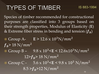
- Classification of timber based on strength properties and durability. The strongest timbers are classified as Group A.
- Key properties of timber including its anisotropic nature, moisture sensitivity, and variability between species. Seasoning and preservative treatment are important.
- Design considerations for flexural members including permissible stresses, shear design, bearing length factors, and deflection limits. Form factors must be applied based on member shape.
- Additional engineered wood products used in construction including glued laminated timber, cross-laminated timber, and plywood.


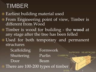

![ Timber is viable to seasonal cracks and
warping
Factor of safety depends on the exposure
conditions (inside, outside & wet) [Table 1]
Well seasoned timber are less liable to
volume changes
Green timber is weak
There is a risk of biological degradation,
when exposed to high moisture
conditions. [Table 2]
Defects in wood include knots, cracks,
wane, shake, dry rot, attack from termites,
white ants, wood borers etc.
5](https://image.slidesharecdn.com/011timber-230216171939-ac534927/85/011-TIMBER-pptx-5-320.jpg)


![24
Cl 7.5.5 Minimum Width > 50mm OR
1/50 of span
Cl 7.5.6 Depth < 3 times width
If Cl 7.5.5 & 7.5.6 cannot be satisfied, lateral stiffening should
be provided to resist bending or buckling
Cl 7.5.7 Shear
Cl 7.5.7.1 Maximum horizontal shear H
When load moves from support towards center &
load is at a distance of 3 to 4 times depth of beam
from support
Cl 7.5.7.2 Vertical end reaction or Shear at a section V
For concentrated & uniformly distributed loads
Cl 7.5.7.3 Deductions in load & Table 6 [Reduction
factors for concentrated loads]
IS 883
Greater](https://image.slidesharecdn.com/011timber-230216171939-ac534927/85/011-TIMBER-pptx-24-320.jpg)