Downloaded 16 times


![19 | P a g e
SAQIB IMRAN 0341-7549889 19
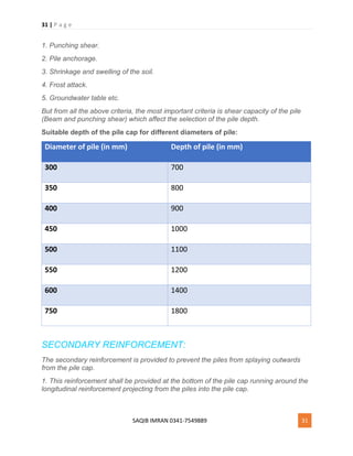
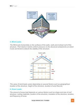
2. The maximum diameter of the ties or helical steel should preferably be not more than
12 mm and 25 mm respectively.
3. The pitch of the ties should not be more than the least of the following
a) Least lateral dimension of the column.
b) 16 times the diameter of the smallest longitudinal bar nearest to the compression
face of the member.
c) 48 times the diameter of the tie.
4. Pitch of the helical reinforcement should not be more than least of the following:
a) 1/6th the diameter of the concrete core.
b) 75mm.
5. The least spacing of the lateral ties may be 150 mm and for spirals, the minimum
pitch shall be 25 mm or three times the diameter of the helical bars whichever is
greater.
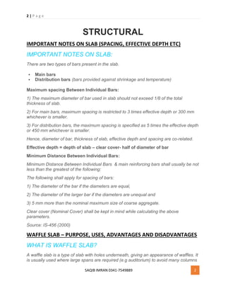
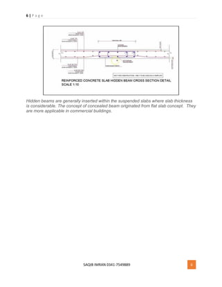
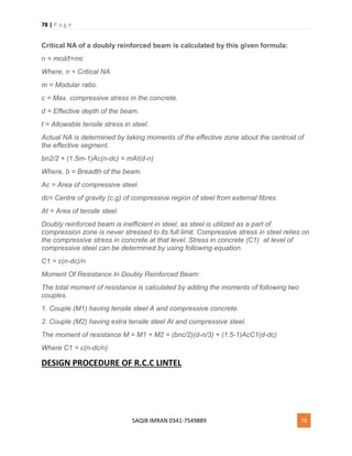
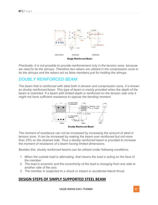
BBS OF LINTEL BEAM – BAR BENDING SCHEDULE OF LINTEL BEAM
BAR BENDING SCHEDULE OF LINTEL BEAM:
In this article, I will discuss how to prepare BBS of RCC Lintel Beam.
1. Calculate Total Length Of Main Bars:
Length of 1 bar = Length of lintel – clear cover for both sides
= 2500 – 2 x 25 [Clear cover for both sides]
=2450 mm](https://image.slidesharecdn.com/structuralpdf-180914102200/85/Structural-pdf-19-320.jpg)
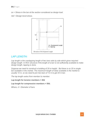


![38 | P a g e
SAQIB IMRAN 0341-7549889 38
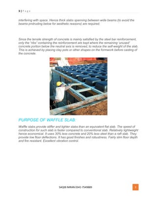
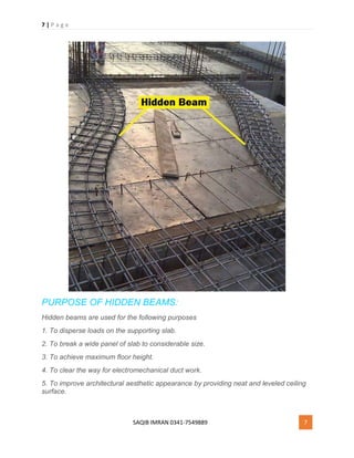
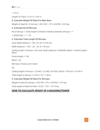
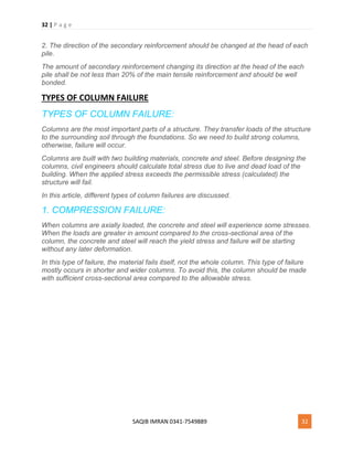
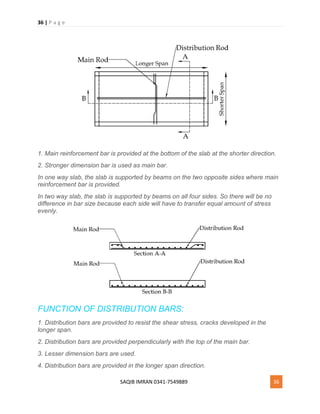
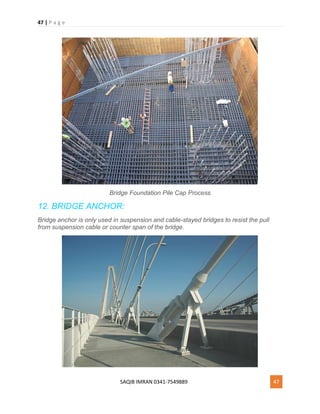
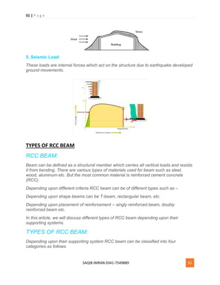
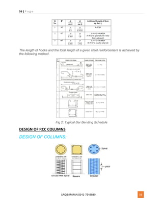
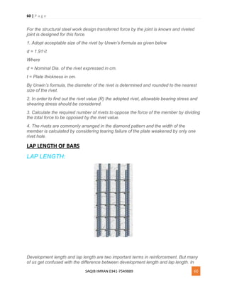
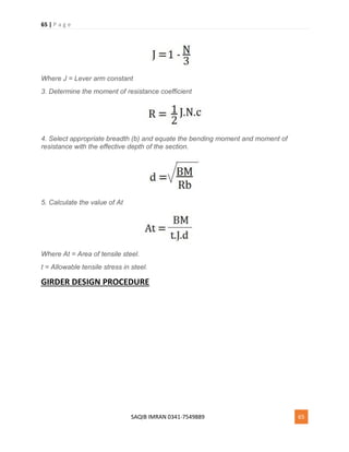
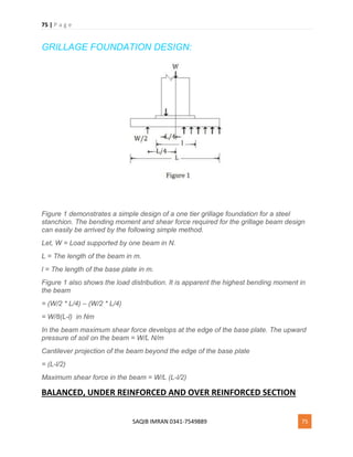
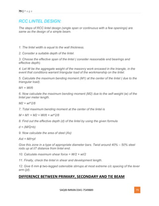
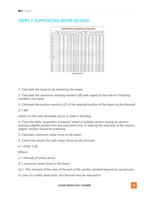
Clear Cover = 25 mm
Clear Span (L) = 8000
Slab Thickness = 200 mm
Development Length(Ld) = 40d
CALCULATION:
Cutting Length = Clear Span of Slab + (2 x Development Length) + (2 x inclined length)
– (45° bend x 4) – (90° bend x 2)
Inclined length = D/(sin 45°) – dD/ (tan 45°) = (D/0.7071) – (D/1)= (1D –
0.7071D)/0.7071= 0.42 D
As you can see there are four 45°bends at the inner side (1,2,3 & 4) and two 90° bends
( a,b ).
45° = 1d ; 90° = 2d
Cutting Length = Clear Span of Slab + (2 X Ld) +(2 x 0.42D) – (1d x 4) – (2d x 2) [BBS
Shape Codes]
Where,
d = Diameter of the bar.
Ld = Development length of bar.
D = Height of the bend bar.
In the above formula, all values are known except ‘D’.
So we need to find out the value of “D”.
D = Slab Thickness – (2 x clear cover) – (diameter of bar)
= 200 – (2 × 25) – 12
= 138 mm](https://image.slidesharecdn.com/structuralpdf-180914102200/85/Structural-pdf-38-320.jpg)


![55 | P a g e
SAQIB IMRAN 0341-7549889 55
8. Weight .
9. Total weight.
From BBS we can know the reinforcement of different bar sizes and bars are cut and
bent appropriately at the job site. It also ensures proper checking and completion of
estimates in a short time. The dimension of bends should be so given in the BBS that
minimum calculation is required for the making of bars and furtherly setting the machine
and stops.
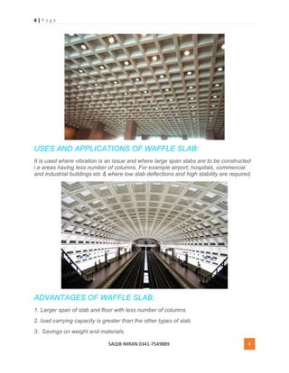
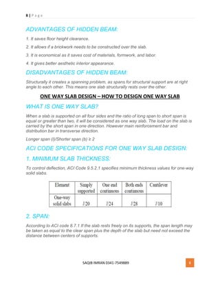
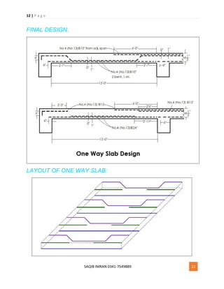
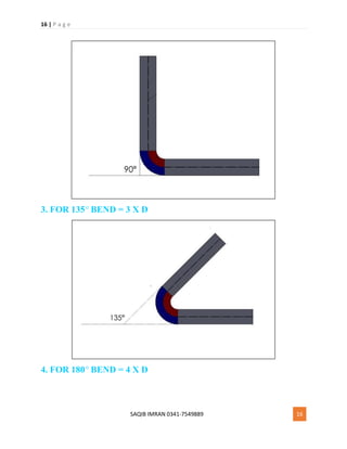
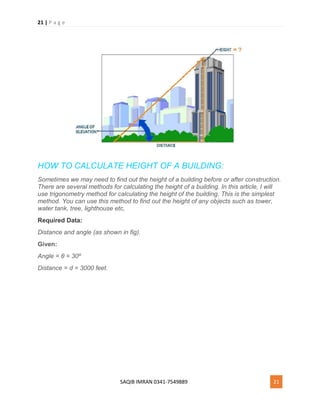
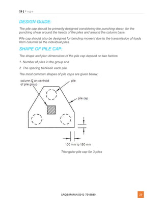
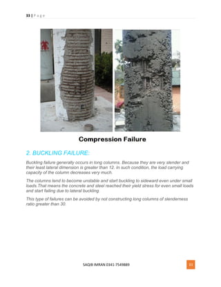
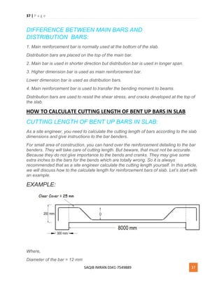
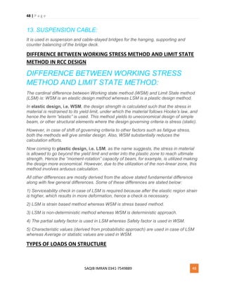
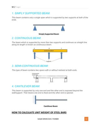
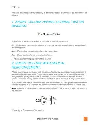
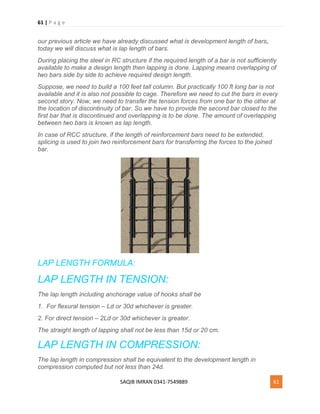
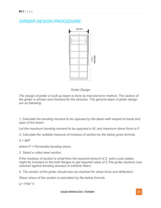
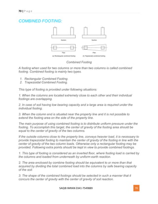
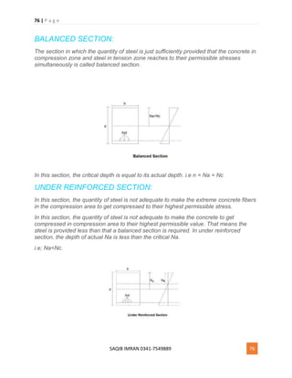
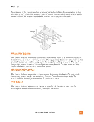
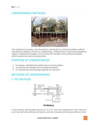
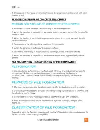
PREPARATION OF BAR BENDING SCHEDULE:
The shapes and proportions of hooks and bends in the reinforcement bars are shown in
Fig. 1– these are standard proportions that are conformed to:
(a) Length of one hook = (4d ) + [(4d+ d )] – where, (4d+ d ) = 9d. (Curved portion)
(b) The additional length (la) that is introduced in the simple, straight end-to-end length
of a reinforcement bar due to bending at θ° say 30o to 60o, generally, 45o is considered)
∴ la= l1 – l2
Fig 1: Hooks and bends in Reinforcement
Let θ = 30°, 45°, 60° respectively](https://image.slidesharecdn.com/structuralpdf-180914102200/85/Structural-pdf-55-320.jpg)
![64 | P a g e
SAQIB IMRAN 0341-7549889 64
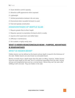
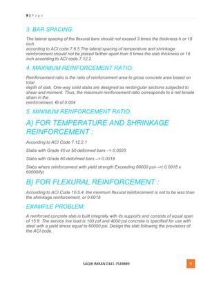
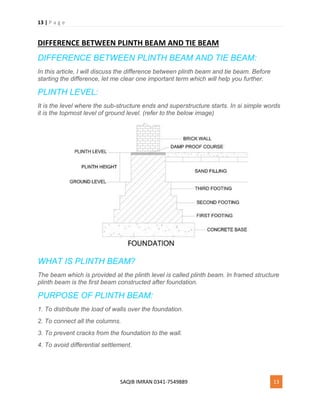
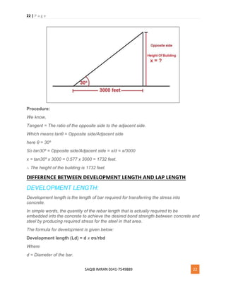
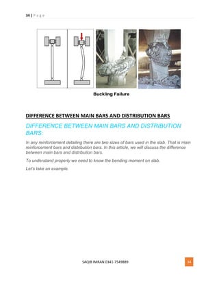
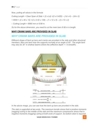
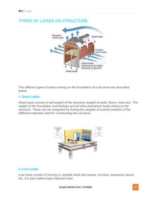
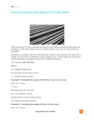
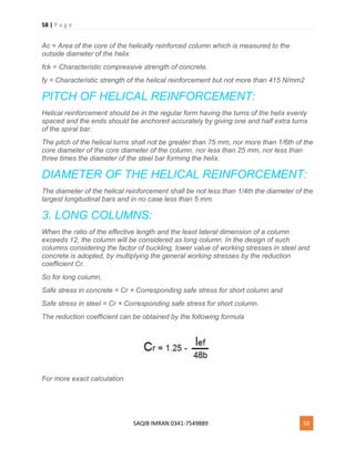
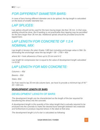
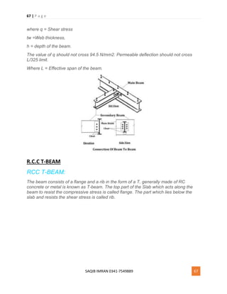
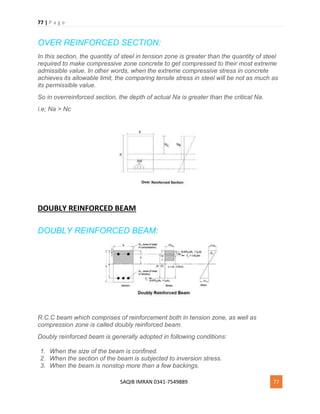
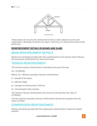
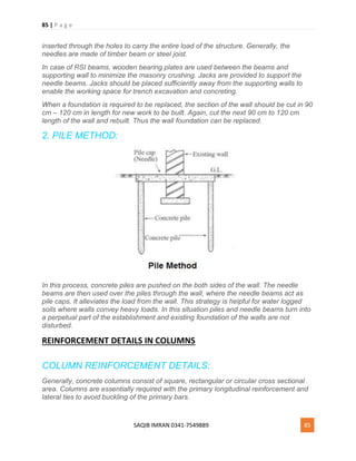
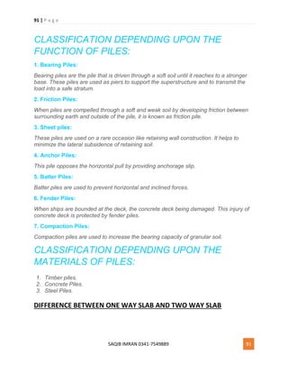
SINGLY REINFORCED BEAM:
Singly Reinforced Beam Design
When the area of steel is provided in tension zone only i.e the reinforcement is given
only in tension zone, it will be known as singly reinforced beam.
In singly reinforced beam, the reinforcement carries the ultimate bending moment and
tension due to bending of the beam. On the other hand, the concrete carries the
compression of that beam.
The actual NA of singly reinforced beam is calculated by the below given formula.
Generally, these types of beams are balanced, under reinforced or over reinforced type.
In practical work, there is no such way to use reinforcement only in tension area,
because we have to bind the stirrups. So, in the compression zone, always two rebars
are used to bind the stirrups where, the rebars just withstand those stirrups.
SINGLY REINFORCED BEAM DESIGN PROCEDURE:
1. Determine the value of N by the following formula:
[Where N = Critical N.A Constant.]
2. Find the value of J.](https://image.slidesharecdn.com/structuralpdf-180914102200/85/Structural-pdf-64-320.jpg)

![74 | P a g e
SAQIB IMRAN 0341-7549889 74
ONE WAY SLAB REINFORCEMENT DETAILS:
For one way slab, main reinforcement is computed by a formula (In limit state design)
that is determined by comparing compressive force as well as tensile forces.
Ast = 0.5 Fck/Fu[1-√1-2.6Mu/Fck.b.d]b.d
and the distribution steel is computed as
0.15% of Ag, for mild steel.
0.12% of Ag, for tor steel.
Where Ast = Area of the steel in tension.
Fu = Ultimate strength of steel.
Mu = Ultimate moment of resistance.
b = Breadth of the slab section.
d = Depth of the slab section.
Ag = Gross area of the section.
DESIGN OF GRILLAGE FOUNDATION](https://image.slidesharecdn.com/structuralpdf-180914102200/85/Structural-pdf-74-320.jpg)


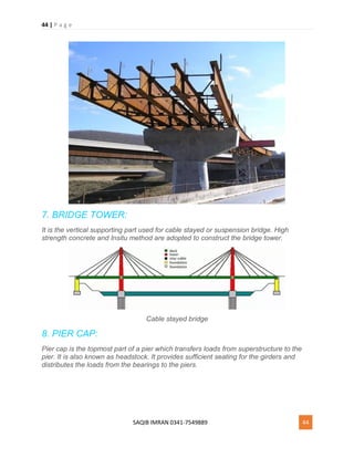
1. The document provides notes on structural engineering topics like slabs, waffle slabs, hidden beams, one-way slabs, and columns. 2. It explains the different types of bars in slabs, the spacing requirements, and how to calculate effective depth. Waffle slabs and hidden beams are described along with their purposes and advantages. 3. The document provides the code specifications for designing a one-way slab and works through an example problem. It also discusses the differences between plinth beams and tie beams.


![presentation on detailing of slab by group TULIP [Autosaved].pptx](https://cdn.slidesharecdn.com/ss_thumbnails/presentationondetailingofslabbygrouptulipautosaved-250830134807-ace00faf-thumbnail.jpg?width=640&height=640&fit=bounds)


