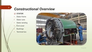
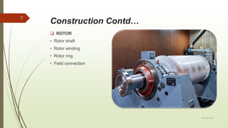
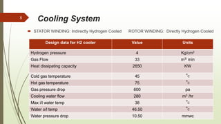
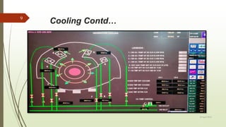
Synchronous Generator
BPSCL 2X250 MW IPP
SHYAM SUNDAR ROY
20 April 2018
1
Presentation outline
20 April 2018
2
 Introduction
 Historical Milestone
 Technical Data
 Constructional Overview
 Cooling System
 Seal Oil System
 Excitation System
 Capability Curves
 Grid Synchronization
 Protections & Tripping
 Generator’s Tests
 Efficiency and Losses
 Research & Development
 References
Basics
 Synchronous : Rotor and RMF rotate with
same speed.
 Generator: Convert rotational mechanical
energy into electrical energy.
 Governed by Fleming’s right hand rule
 Operation based on Faraday’s laws of EMT.
 Emf Equation: 4.44Kc Kd ɸ Z
 Induced emf = -ɗɸ / ɗʈ
20 April 2018
3
1866-83
• Designed by Ganz Works
• Dynamo Gen Production started
for hydro power
1887
• DC dynamo based Turbo
generator designed
• Engaged in Thermal Power Plants
1901
• Supplied first industrial turbo
generator
• Installed in Eberfield, Germany
Chronological Aspects
20 April 2018
4
Technical Data
BHARAT HEAVY ELECTRICALS LIMITED
TURBOGENERATOR
TYPE: TG-HH-0250-2 PO.NO-10281-A-131-01
10282-A-131-01
3 Phase 50Hz YY PF: 0.85Lag
294.1 MVA 250MW
16.5KV 10291A 3000RPM
Coolant : Hydrogen Spec: IS-5422 IEC-34
Gas Pressure: 4KSC Insulation Class: F
Excitation Voltage: 300V, Current : 2497A
Division : Haridwar Year: 2010
20 April 2018
5
Constructional Overview
20 April 2018
6
 STATOR
• Stator frame
• Stator core
• Stator winding
• End cover
• Bushings
• Terminal box
Construction Contd…

 ROTOR
• Rotor shaft
• Rotor winding
• Rotor ring
• Field connection
20 April 2018
7
Cooling System
 STATOR WINDING: Indirectly Hydrogen Cooled ROTOR WINDING: Directly Hydrogen Cooled
20 April 2018
8
Design data for H2 cooler Value Units
Hydrogen pressure 4 Kg/cm2
Gas Flow 33 m3/ min
Heat dissipating capacity 2650 KW
Cold gas temperature 45
o
C
Hot gas temperature 75
o
C
Gas pressure drop 600 pa
Cooling water flow 280 m3 /hr
Max i/l water temp 38
o
C
Water o/l temp 46.50
o
C
Water pressure drop 10.50 mmwc
Cooling Contd…
20 April 2018
9
Seal Oil System
Design Data Value Units
Oil Flow 7.8 m3/ hr
Heat dissipating
Capacity
100 KW
Oil Inlet temp 70 oc
Oil outlet temp 43 oc
Oil Press drop 0.15 Bar
Cooling Water flow 17.4 M3/hr
Max i/l water temp 38 oc
Water o/l temp 43 oc
Water press drop 0.15 mmwc
 Major Components
 Seal oil storage tank(in bearing drain line)
 Seal oil vacuum pump
 Intermediate oil tank
 Downstream pump pressure controller
 Seal oil coolers
 Seal oil filters
 Differential pressures control valves
20 April 2018
10
Sealing Contd…
20 April 2018
11
Excitation System
 Brushless Excitation
 Static Excitation
 Main Components
 Pilot exciter
 Main exciter
 Rectifier wheel
 Automatic voltage regulator
20 April 2018
12
Brushless Excitation
20 April 2018
13
Excitation Contd..
20 April 2018
14
Capability Curves
 Limiting factors are rotor and stator thermal
limits
 Under excited limiting factor is stator end iron
heat.
 Excitation control setting control is
coordinated with steady-state stability limit
(SSSL)
 Minimum excitation limiter (MEL) prevents
exciter from reducing the field below SSSL
20 April 2018
15
Curves Contd…
20 April 2018
16
System Stability
20 April 2018
17
Stability Contd…
 Graphical technique used to examine
the transient stability of the machine
systems (one or more than one) with an
infinite bus.
 Stability conditions are stated by
equating the two area segments which is
present in the power angle diagram.
The KE stored during acceleration is
mentioned as A1, and the KE stored
during deceleration is mentioned
as A2. PA becomes zero when it has both
decelerating power and accelerating
powers.
This criterion method helps to
determine the greatest limit on the load
without affecting the stability limit.
20 April 2018
18
Mathematical Approach
 The equation governing the rotor motion is
given by Swing equation.
 A Synchronous generator is driven by a prime
mover.
 power exchange between the mechanical
rotor and the electrical grid due to the rotor
swing.
20 April 2018
19
Grid Synchronization
 In order to synchronize a generator to
the grid, four conditions must be met:
 Phase Angle
 Frequency
 Voltage Magnitude
 Phase Sequence
 More info on given link
 https://www.youtube.com/watch?v=FI_0
7YVS3tY
20 April 2018
20
Phase Angle
 The phase angle between the
voltage produced by the generator and
the voltage produced by the
grid must be zero.
The phase angle (0 to 360°) can be
readily observed by comparing the
simultaneous occurrence of the peaks
or zero crossings of the sinusoidal
waveforms.
At that instance (Figure 4 below), the
pointer on the synchroscope would
indicate 12:00 o'clock.
20 April 2018
21
Frequency
The frequency of the sinusoidal voltage
produced by the generator must be equal to
the frequency of the sinusoidal voltage
produced by the grid.
 If generator’s frequency were than grid.
The synchroscope would be rotating rapidly
counter clockwise. If the generator breaker
were to be accidentally closed, the generator
would be out of step with the external
electrical system. It would behave like motor
and the grid would try to bring it up to speed.
20 April 2018
22
Frequency Contd…
If the generator were faster than the grid
the rotor and stator would be slipping poles and
possibly destroy the generator.
If the generator breaker were to be closed at
this time, the grid would pull the generator into
step.
If the generator breaker were to be closed at
this time, the grid would pull the generator into
step.
This would cause a large current in-rush to
the generator and high stresses on the
rotor/stator with subsequent damage to the
generator If the generator were leading the grid.
20 April 2018
23
Voltage Magnitude
 The magnitude of the sinusoidal voltage produced by the generator must be equal
to the magnitude of the sinusoidal voltage of the grid.
 If the generator voltage is higher than the grid voltage, this means that the
internal voltage of the generator is higher than the grid voltage. When it
is connected to the grid the generator will be overexcited and it will inject MVAR.
 If the generator voltage is less than the grid voltage, this means that the
internal voltage of the generator is lower than the grid voltage. When it is
connected to the grid the generator will be under-excited and it will absorb MVAR.
20 April 2018
24
Phase Sequence
The phase sequence of the three
phases of the generator must be the
same as the phase sequence of the
three phases of the electrical
system (Grid).
20 April 2018
25
Protections Schemes
 Generator Differential protection
 Generator Stator E/F(0-100%)
 Backup Impedance Protection
 Reverse Power Protection
 Gen Under voltage Protection
 Loss of Excitation Protection
 Gen Pole Slipping Protection
 Generator Dead M/C Optd
 Rotor E/F Stage-2 Optd
 Gen Over Voltage Protection
 Negative Phase Sequence Protection
 Gen Under Frequency protection
 Gen Over Frequency Protection
 GRP-1&2 Relay Faulty
 Over Fluxing Protection
 186A/286A Relay Faulty
 186B/286B Relay Faulty
 Generator DC Supply Fail protection
20 April 2018
26
Tripping Logics
20 April 2018
27
Generator
Tests
Electrical Tests
Open circuit test
Short circuit test
High voltage test
Inter stand test
Mechanical Tests
Vibration test
Temperature test
 NDT test
20 April 2018
28
Major Losses
 Core loss
 Copper loss
 Windage loss
 Friction loss
 Diode drop loss
 Restive loss
 Thermal loss
 Counter Emf
20 April 2018
29
Efficiency Calculation
 Efficiency = Output energy / Input energy
 ɳ = 1/ Heat Rate
 ɳ = Output / output +losses
20 April 2018
30
Research & Developments
 In the field of electromagnetic, the focus lies on highly precise prediction of the
electromagnetic and thermal data to optimize generator parameters, efficiency and
size.
 R&D focuses are on new and improved design concepts, precise vibration and
noise analysis.
 Cooling optimization needs precise ventilation design tools, including heat transfer
calculations with modern CFD (computational fluid dynamics) and CHT (conjugate
heat transfer) methods.
20 April 2018
31
References
 Literatures
 A text book of Turbo generator, NPTI Publications
 A text book of Machines Protections, NPTI Publications
 BHEL Haridwar Internal material
 Websites
 http://www.bhel.com
 http://www.cea.nic.in/
 http://www.cpri.in/index.php
 http://en.wikipedia.org/wiki/Turbo_generator
 http://en.wikipedia.org/wiki/Hydrogen-cooled_turbogenerator
20 April 2018
32
Thank You !
20 April 2018
33

Synchronous generator

  • 1.
    Synchronous Generator BPSCL 2X250MW IPP SHYAM SUNDAR ROY 20 April 2018 1
  • 2.
    Presentation outline 20 April2018 2  Introduction  Historical Milestone  Technical Data  Constructional Overview  Cooling System  Seal Oil System  Excitation System  Capability Curves  Grid Synchronization  Protections & Tripping  Generator’s Tests  Efficiency and Losses  Research & Development  References
  • 3.
    Basics  Synchronous :Rotor and RMF rotate with same speed.  Generator: Convert rotational mechanical energy into electrical energy.  Governed by Fleming’s right hand rule  Operation based on Faraday’s laws of EMT.  Emf Equation: 4.44Kc Kd ɸ Z  Induced emf = -ɗɸ / ɗʈ 20 April 2018 3
  • 4.
    1866-83 • Designed byGanz Works • Dynamo Gen Production started for hydro power 1887 • DC dynamo based Turbo generator designed • Engaged in Thermal Power Plants 1901 • Supplied first industrial turbo generator • Installed in Eberfield, Germany Chronological Aspects 20 April 2018 4
  • 5.
    Technical Data BHARAT HEAVYELECTRICALS LIMITED TURBOGENERATOR TYPE: TG-HH-0250-2 PO.NO-10281-A-131-01 10282-A-131-01 3 Phase 50Hz YY PF: 0.85Lag 294.1 MVA 250MW 16.5KV 10291A 3000RPM Coolant : Hydrogen Spec: IS-5422 IEC-34 Gas Pressure: 4KSC Insulation Class: F Excitation Voltage: 300V, Current : 2497A Division : Haridwar Year: 2010 20 April 2018 5
  • 6.
    Constructional Overview 20 April2018 6  STATOR • Stator frame • Stator core • Stator winding • End cover • Bushings • Terminal box
  • 7.
    Construction Contd…   ROTOR •Rotor shaft • Rotor winding • Rotor ring • Field connection 20 April 2018 7
  • 8.
    Cooling System  STATORWINDING: Indirectly Hydrogen Cooled ROTOR WINDING: Directly Hydrogen Cooled 20 April 2018 8 Design data for H2 cooler Value Units Hydrogen pressure 4 Kg/cm2 Gas Flow 33 m3/ min Heat dissipating capacity 2650 KW Cold gas temperature 45 o C Hot gas temperature 75 o C Gas pressure drop 600 pa Cooling water flow 280 m3 /hr Max i/l water temp 38 o C Water o/l temp 46.50 o C Water pressure drop 10.50 mmwc
  • 9.
  • 10.
    Seal Oil System DesignData Value Units Oil Flow 7.8 m3/ hr Heat dissipating Capacity 100 KW Oil Inlet temp 70 oc Oil outlet temp 43 oc Oil Press drop 0.15 Bar Cooling Water flow 17.4 M3/hr Max i/l water temp 38 oc Water o/l temp 43 oc Water press drop 0.15 mmwc  Major Components  Seal oil storage tank(in bearing drain line)  Seal oil vacuum pump  Intermediate oil tank  Downstream pump pressure controller  Seal oil coolers  Seal oil filters  Differential pressures control valves 20 April 2018 10
  • 11.
  • 12.
    Excitation System  BrushlessExcitation  Static Excitation  Main Components  Pilot exciter  Main exciter  Rectifier wheel  Automatic voltage regulator 20 April 2018 12
  • 13.
  • 14.
  • 15.
    Capability Curves  Limitingfactors are rotor and stator thermal limits  Under excited limiting factor is stator end iron heat.  Excitation control setting control is coordinated with steady-state stability limit (SSSL)  Minimum excitation limiter (MEL) prevents exciter from reducing the field below SSSL 20 April 2018 15
  • 16.
  • 17.
  • 18.
    Stability Contd…  Graphicaltechnique used to examine the transient stability of the machine systems (one or more than one) with an infinite bus.  Stability conditions are stated by equating the two area segments which is present in the power angle diagram. The KE stored during acceleration is mentioned as A1, and the KE stored during deceleration is mentioned as A2. PA becomes zero when it has both decelerating power and accelerating powers. This criterion method helps to determine the greatest limit on the load without affecting the stability limit. 20 April 2018 18
  • 19.
    Mathematical Approach  Theequation governing the rotor motion is given by Swing equation.  A Synchronous generator is driven by a prime mover.  power exchange between the mechanical rotor and the electrical grid due to the rotor swing. 20 April 2018 19
  • 20.
    Grid Synchronization  Inorder to synchronize a generator to the grid, four conditions must be met:  Phase Angle  Frequency  Voltage Magnitude  Phase Sequence  More info on given link  https://www.youtube.com/watch?v=FI_0 7YVS3tY 20 April 2018 20
  • 21.
    Phase Angle  Thephase angle between the voltage produced by the generator and the voltage produced by the grid must be zero. The phase angle (0 to 360°) can be readily observed by comparing the simultaneous occurrence of the peaks or zero crossings of the sinusoidal waveforms. At that instance (Figure 4 below), the pointer on the synchroscope would indicate 12:00 o'clock. 20 April 2018 21
  • 22.
    Frequency The frequency ofthe sinusoidal voltage produced by the generator must be equal to the frequency of the sinusoidal voltage produced by the grid.  If generator’s frequency were than grid. The synchroscope would be rotating rapidly counter clockwise. If the generator breaker were to be accidentally closed, the generator would be out of step with the external electrical system. It would behave like motor and the grid would try to bring it up to speed. 20 April 2018 22
  • 23.
    Frequency Contd… If thegenerator were faster than the grid the rotor and stator would be slipping poles and possibly destroy the generator. If the generator breaker were to be closed at this time, the grid would pull the generator into step. If the generator breaker were to be closed at this time, the grid would pull the generator into step. This would cause a large current in-rush to the generator and high stresses on the rotor/stator with subsequent damage to the generator If the generator were leading the grid. 20 April 2018 23
  • 24.
    Voltage Magnitude  Themagnitude of the sinusoidal voltage produced by the generator must be equal to the magnitude of the sinusoidal voltage of the grid.  If the generator voltage is higher than the grid voltage, this means that the internal voltage of the generator is higher than the grid voltage. When it is connected to the grid the generator will be overexcited and it will inject MVAR.  If the generator voltage is less than the grid voltage, this means that the internal voltage of the generator is lower than the grid voltage. When it is connected to the grid the generator will be under-excited and it will absorb MVAR. 20 April 2018 24
  • 25.
    Phase Sequence The phasesequence of the three phases of the generator must be the same as the phase sequence of the three phases of the electrical system (Grid). 20 April 2018 25
  • 26.
    Protections Schemes  GeneratorDifferential protection  Generator Stator E/F(0-100%)  Backup Impedance Protection  Reverse Power Protection  Gen Under voltage Protection  Loss of Excitation Protection  Gen Pole Slipping Protection  Generator Dead M/C Optd  Rotor E/F Stage-2 Optd  Gen Over Voltage Protection  Negative Phase Sequence Protection  Gen Under Frequency protection  Gen Over Frequency Protection  GRP-1&2 Relay Faulty  Over Fluxing Protection  186A/286A Relay Faulty  186B/286B Relay Faulty  Generator DC Supply Fail protection 20 April 2018 26
  • 27.
  • 28.
    Generator Tests Electrical Tests Open circuittest Short circuit test High voltage test Inter stand test Mechanical Tests Vibration test Temperature test  NDT test 20 April 2018 28
  • 29.
    Major Losses  Coreloss  Copper loss  Windage loss  Friction loss  Diode drop loss  Restive loss  Thermal loss  Counter Emf 20 April 2018 29
  • 30.
    Efficiency Calculation  Efficiency= Output energy / Input energy  ɳ = 1/ Heat Rate  ɳ = Output / output +losses 20 April 2018 30
  • 31.
    Research & Developments In the field of electromagnetic, the focus lies on highly precise prediction of the electromagnetic and thermal data to optimize generator parameters, efficiency and size.  R&D focuses are on new and improved design concepts, precise vibration and noise analysis.  Cooling optimization needs precise ventilation design tools, including heat transfer calculations with modern CFD (computational fluid dynamics) and CHT (conjugate heat transfer) methods. 20 April 2018 31
  • 32.
    References  Literatures  Atext book of Turbo generator, NPTI Publications  A text book of Machines Protections, NPTI Publications  BHEL Haridwar Internal material  Websites  http://www.bhel.com  http://www.cea.nic.in/  http://www.cpri.in/index.php  http://en.wikipedia.org/wiki/Turbo_generator  http://en.wikipedia.org/wiki/Hydrogen-cooled_turbogenerator 20 April 2018 32
  • 33.
    Thank You ! 20April 2018 33