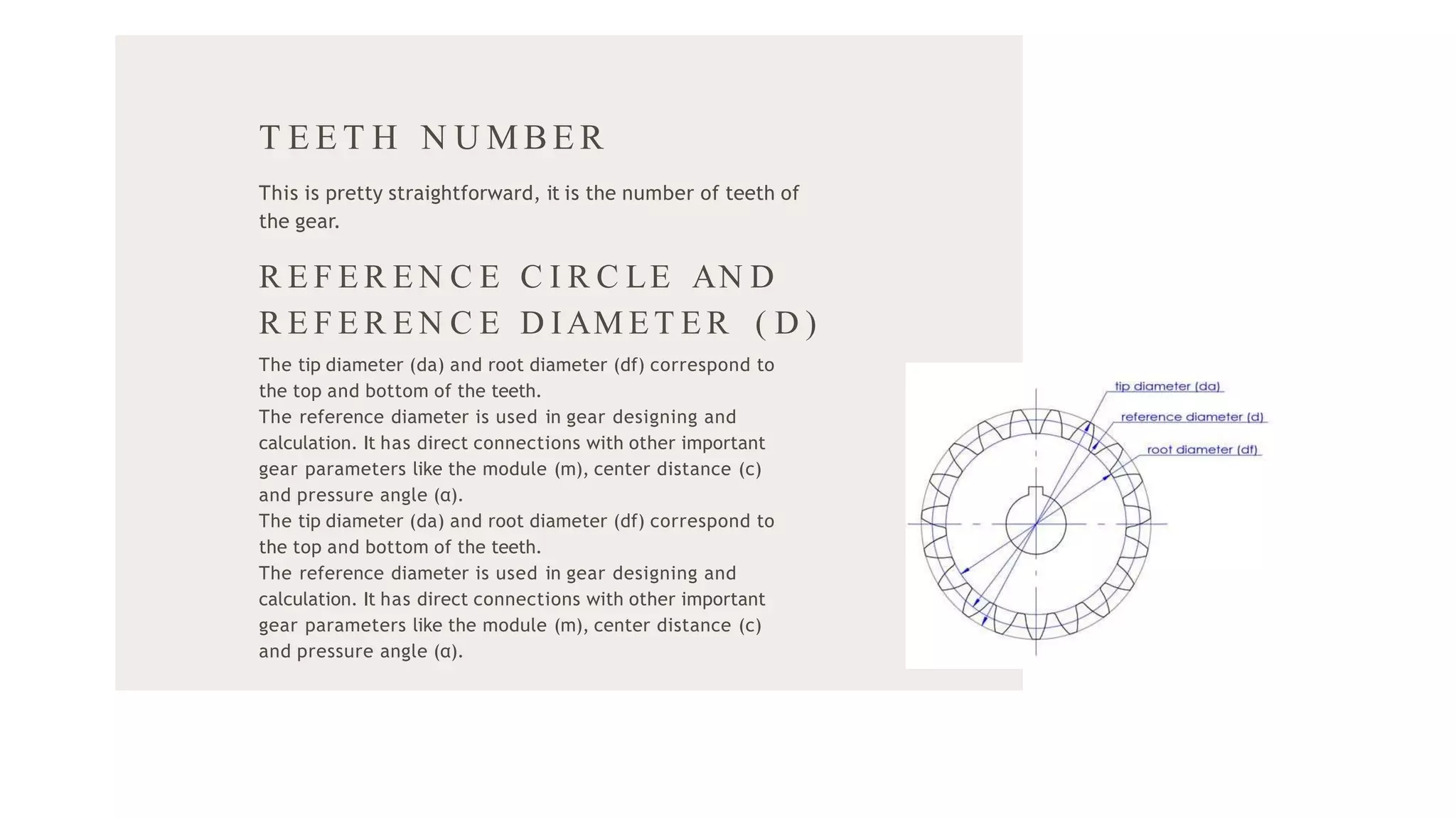
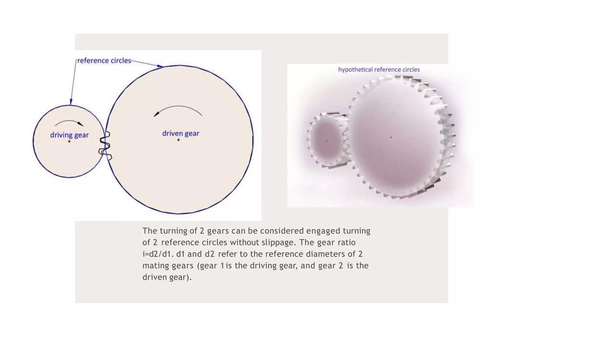
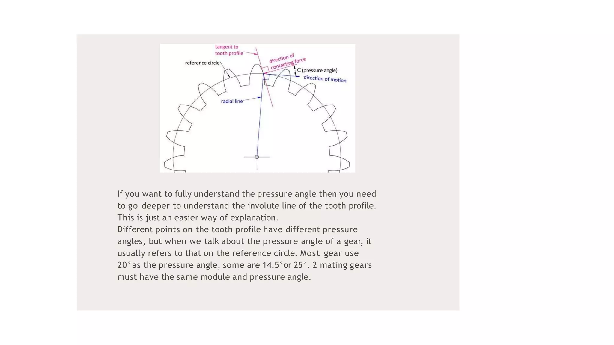
G EA R T O O T H
N O MEN C L A T U R E
P R E S E N T A T I O N B Y S E L V A L A K S H M I M
The slip and creep in the belt or rope drives is a common
phenomenon, in the transmission of motion or power between
two shafts. The effect of slip is to reduce the velocity ratio of the
drive. In precision machine, in which a definite velocity ratio is
importance (as in watch mechanism, special purpose
machines..etc), the only positive drive is by means of gears or
toothed wheels.
IN T R O D U C T IO N
Addendum :The radial distance between the
Pitch Circle and the top of the teeth.
01
02
03
04
Arc of Action: Is the arc of the Pitch Circle
between the beginning and the end of
theengagement of a given pair of teeth.
Arc of Approach: Is the arc of the Pitch Circle
between the first point of contact of the gear
teeth and the Pitch Point.
Arc of Recession: That arc of the Pitch Circle
between the Pitch Point and the last point of
contact of the gear teeth.
G EA R T ER MIN O L O G Y
Backlash: Play between mating teeth.
05
06
07
08
Base Circle: The circle from which is generated
the involute curve upon which the tooth profile
is based.
Center Distance: The distance between centers
of two gears.
Chordal Addendum: The distance between a
chord, passing through the points where the
Pitch Circle crosses the tooth profile, and the
tooth top.
Chordal Thickness:The thickness of the tooth
measured along a chord passing through the
points where the Pitch Circle crosses the tooth
profile.
09
Circular Pitch: Millimeter of Pitch Circle
circumference per tooth.
10
11
12
Circular Thickness: The thickness of the tooth
measured along an arc following the Pitch
Circle.
Clearance: The distance between the top of a
tooth and the bottom of the space into which it
fits on the meshing gear.
Contact Ratio: The ratio of the length of the Arc
of Action to the Circular Pitch.
13
14
15
16
Dedendum: The radial distance between the
bottom of the tooth to pitch circle.
Diametral Pitch: Teeth per mm of diameter.
Face: The working surface of a gear tooth,
located between the pitch diameter and the top
of the tooth.
Face Width: The width of the tooth measured
parallel to the gear axis.
17
18
19
20
Flank: The working surface of a gear tooth,
located between the pitch diameter and the
bottom of the teeth
Wheel:Larger of the two meshing gears is called
wheel.
Pinion: The smaller of the two meshing gears is
called pinion.
Land: The top surface of the tooth.
21
Line of Action: That line along which the point
of contact between gear teeth travels, between
the first point of contact and the last.
22
23
24
Module: Ratio of Pitch Diameter to the number
of teeth.
Pitch Circle: The circle, the radius of which is
equal to the distance from the center of the
gear to the pitch point.
Diametral pitch: Ratio of the number of teeth to
the of pitch circle diameter.
25
Pitch Point: The point of tangency of the pitch
circles of two meshing gears, where the Line of
Centers crosses the pitch circles.
26
27
28
Pressure Angle: Angle between the Line of
Action and a line perpendicular to the Line of
Centers.
Profile Shift: An increase in the Outer Diameter
and Root Diameter of a gear, introduced to
lower the practical tooth number or acheive a
non-standard Center Distance.
Ratio: Ratio of the numbers of teeth on mating
gears.
29
30
31
32
Root Circle: The circle that passes through the
bottom of the tooth spaces.
Root Diameter: The diameter of the Root Circle.
Working Depth: The depth to which a tooth
extends into the space between teeth on the
mating gear.
G E A R N O M E N C L A T U R E
Teeth number
Reference circle and reference diameter
Module
Center distance
Pressure angle
BAS I C G E AR T E R M I N O L O G Y
T E E T H N U M BE R
This is pretty straightforward, it is the number of teeth of
the gear.
R E F E R E N C E C I R C LE AN D
R E F E R E N C E D IAM ET E R ( D )
The tip diameter (da) and root diameter (df) correspond to
the top and bottom of the teeth.
The reference diameter is used in gear designing and
calculation. It has direct connections with other important
gear parameters like the module (m), center distance (c)
and pressure angle (α).
The tip diameter (da) and root diameter (df) correspond to
the top and bottom of the teeth.
The reference diameter is used in gear designing and
calculation. It has direct connections with other important
gear parameters like the module (m), center distance (c)
and pressure angle (α).
The turning of 2 gears can be considered engaged turning
of 2 reference circles without slippage. The gear ratio
i=d2/d1. d1 and d2 refer to the reference diameters of 2
mating gears (gear 1is the driving gear, and gear 2 is the
driven gear).
M O D U LE
The module is probably the most important gear parameter,
and it appears almost everywhere in teeth calculation
formulas. Actually, it is not so difficult to understand as you
might imagine. First let’s understand what the pitch is, Pitch
is the arc length between corresponding points on adjacent
teeth, usually on the reference circle.
Then we have the reference diameter d=circumference/
π=pitch*z/π, to make the calculation easier, we define the
pitch/π as the module, and now we have the equation of
d=m*z.
C E N T E R D I S T AN C E ( A)
2 meshing gears always have the same module
otherwise they don’t match. Now we can come to
the conclusion that a=(d1+d2)/2=m(z1+z2)/2, but it
can be slightly different while making some
adjustments on the gear geometries (tooth profile
shifting).
P R E S S U R E AN G LE
Simply put, as its name suggests, it is the angle between the
direction of contacting force on the contact point of the
tooth and direction of motion of that point on the tooth
profile.
In geometry, it is the angle between the line normal to the
involute tooth profile and the line normal to its radial line.
If you want to fully understand the pressure angle then you need
to go deeper to understand the involute line of the tooth profile.
This is just an easier way of explanation.
Different points on the tooth profile have different pressure
angles, but when we talk about the pressure angle of a gear, it
usually refers to that on the reference circle. Most gear use
20°as the pressure angle, some are 14.5°or 25°. 2 mating gears
must have the same module and pressure angle.
T H AN K YO U

Gear Tooth Nomenclature.pptx

  • 1.
    G EA RT O O T H N O MEN C L A T U R E P R E S E N T A T I O N B Y S E L V A L A K S H M I M
  • 2.
    The slip andcreep in the belt or rope drives is a common phenomenon, in the transmission of motion or power between two shafts. The effect of slip is to reduce the velocity ratio of the drive. In precision machine, in which a definite velocity ratio is importance (as in watch mechanism, special purpose machines..etc), the only positive drive is by means of gears or toothed wheels. IN T R O D U C T IO N
  • 3.
    Addendum :The radialdistance between the Pitch Circle and the top of the teeth. 01 02 03 04 Arc of Action: Is the arc of the Pitch Circle between the beginning and the end of theengagement of a given pair of teeth. Arc of Approach: Is the arc of the Pitch Circle between the first point of contact of the gear teeth and the Pitch Point. Arc of Recession: That arc of the Pitch Circle between the Pitch Point and the last point of contact of the gear teeth. G EA R T ER MIN O L O G Y Backlash: Play between mating teeth. 05 06 07 08 Base Circle: The circle from which is generated the involute curve upon which the tooth profile is based. Center Distance: The distance between centers of two gears. Chordal Addendum: The distance between a chord, passing through the points where the Pitch Circle crosses the tooth profile, and the tooth top.
  • 4.
    Chordal Thickness:The thicknessof the tooth measured along a chord passing through the points where the Pitch Circle crosses the tooth profile. 09 Circular Pitch: Millimeter of Pitch Circle circumference per tooth. 10 11 12 Circular Thickness: The thickness of the tooth measured along an arc following the Pitch Circle. Clearance: The distance between the top of a tooth and the bottom of the space into which it fits on the meshing gear. Contact Ratio: The ratio of the length of the Arc of Action to the Circular Pitch. 13 14 15 16 Dedendum: The radial distance between the bottom of the tooth to pitch circle. Diametral Pitch: Teeth per mm of diameter. Face: The working surface of a gear tooth, located between the pitch diameter and the top of the tooth.
  • 5.
    Face Width: Thewidth of the tooth measured parallel to the gear axis. 17 18 19 20 Flank: The working surface of a gear tooth, located between the pitch diameter and the bottom of the teeth Wheel:Larger of the two meshing gears is called wheel. Pinion: The smaller of the two meshing gears is called pinion. Land: The top surface of the tooth. 21 Line of Action: That line along which the point of contact between gear teeth travels, between the first point of contact and the last. 22 23 24 Module: Ratio of Pitch Diameter to the number of teeth. Pitch Circle: The circle, the radius of which is equal to the distance from the center of the gear to the pitch point.
  • 6.
    Diametral pitch: Ratioof the number of teeth to the of pitch circle diameter. 25 Pitch Point: The point of tangency of the pitch circles of two meshing gears, where the Line of Centers crosses the pitch circles. 26 27 28 Pressure Angle: Angle between the Line of Action and a line perpendicular to the Line of Centers. Profile Shift: An increase in the Outer Diameter and Root Diameter of a gear, introduced to lower the practical tooth number or acheive a non-standard Center Distance. Ratio: Ratio of the numbers of teeth on mating gears. 29 30 31 32 Root Circle: The circle that passes through the bottom of the tooth spaces. Root Diameter: The diameter of the Root Circle. Working Depth: The depth to which a tooth extends into the space between teeth on the mating gear.
  • 7.
    G E AR N O M E N C L A T U R E
  • 8.
    Teeth number Reference circleand reference diameter Module Center distance Pressure angle BAS I C G E AR T E R M I N O L O G Y
  • 9.
    T E ET H N U M BE R This is pretty straightforward, it is the number of teeth of the gear. R E F E R E N C E C I R C LE AN D R E F E R E N C E D IAM ET E R ( D ) The tip diameter (da) and root diameter (df) correspond to the top and bottom of the teeth. The reference diameter is used in gear designing and calculation. It has direct connections with other important gear parameters like the module (m), center distance (c) and pressure angle (α). The tip diameter (da) and root diameter (df) correspond to the top and bottom of the teeth. The reference diameter is used in gear designing and calculation. It has direct connections with other important gear parameters like the module (m), center distance (c) and pressure angle (α).
  • 10.
    The turning of2 gears can be considered engaged turning of 2 reference circles without slippage. The gear ratio i=d2/d1. d1 and d2 refer to the reference diameters of 2 mating gears (gear 1is the driving gear, and gear 2 is the driven gear).
  • 11.
    M O DU LE The module is probably the most important gear parameter, and it appears almost everywhere in teeth calculation formulas. Actually, it is not so difficult to understand as you might imagine. First let’s understand what the pitch is, Pitch is the arc length between corresponding points on adjacent teeth, usually on the reference circle. Then we have the reference diameter d=circumference/ π=pitch*z/π, to make the calculation easier, we define the pitch/π as the module, and now we have the equation of d=m*z.
  • 12.
    C E NT E R D I S T AN C E ( A) 2 meshing gears always have the same module otherwise they don’t match. Now we can come to the conclusion that a=(d1+d2)/2=m(z1+z2)/2, but it can be slightly different while making some adjustments on the gear geometries (tooth profile shifting).
  • 13.
    P R ES S U R E AN G LE Simply put, as its name suggests, it is the angle between the direction of contacting force on the contact point of the tooth and direction of motion of that point on the tooth profile. In geometry, it is the angle between the line normal to the involute tooth profile and the line normal to its radial line.
  • 14.
    If you wantto fully understand the pressure angle then you need to go deeper to understand the involute line of the tooth profile. This is just an easier way of explanation. Different points on the tooth profile have different pressure angles, but when we talk about the pressure angle of a gear, it usually refers to that on the reference circle. Most gear use 20°as the pressure angle, some are 14.5°or 25°. 2 mating gears must have the same module and pressure angle.
  • 15.
    T H ANK YO U