Downloaded 112 times


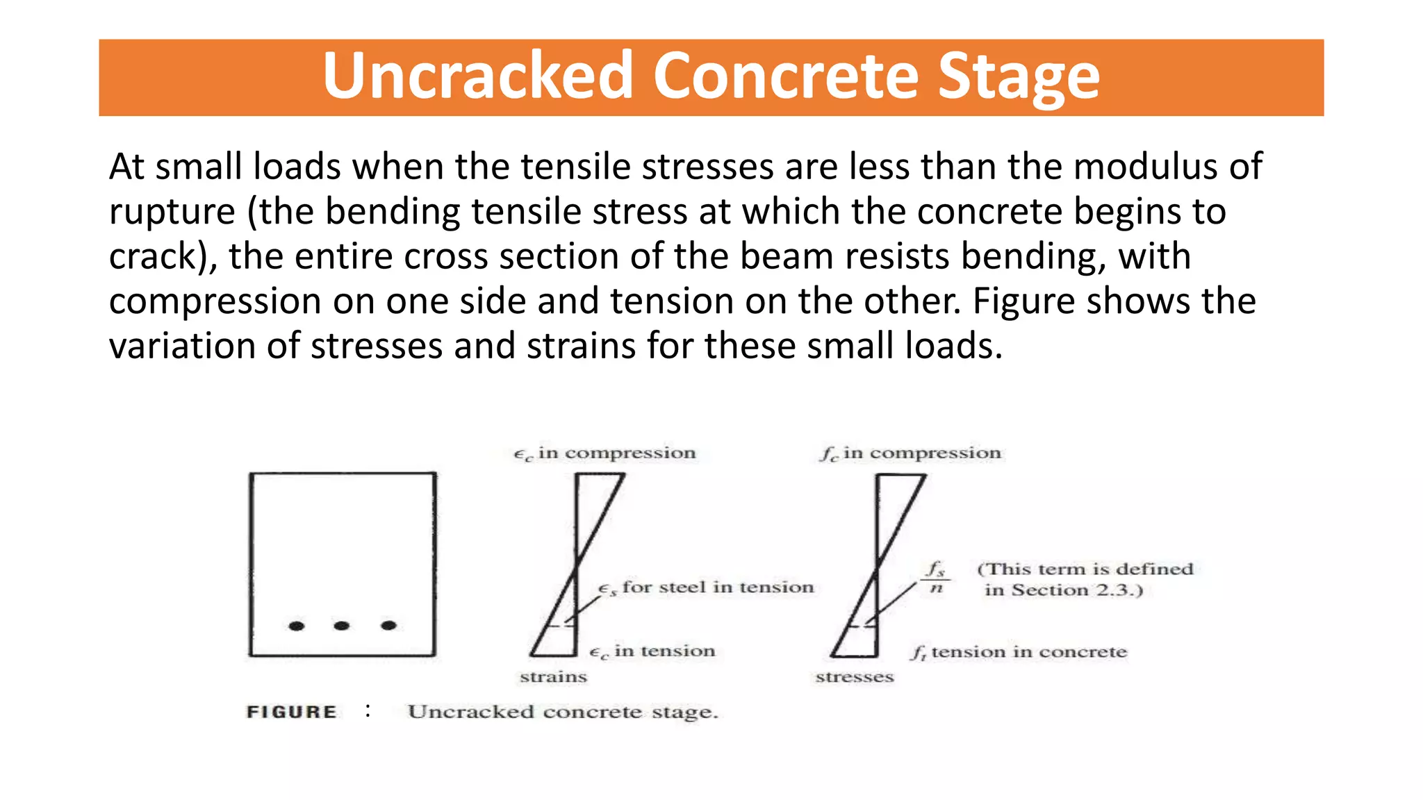

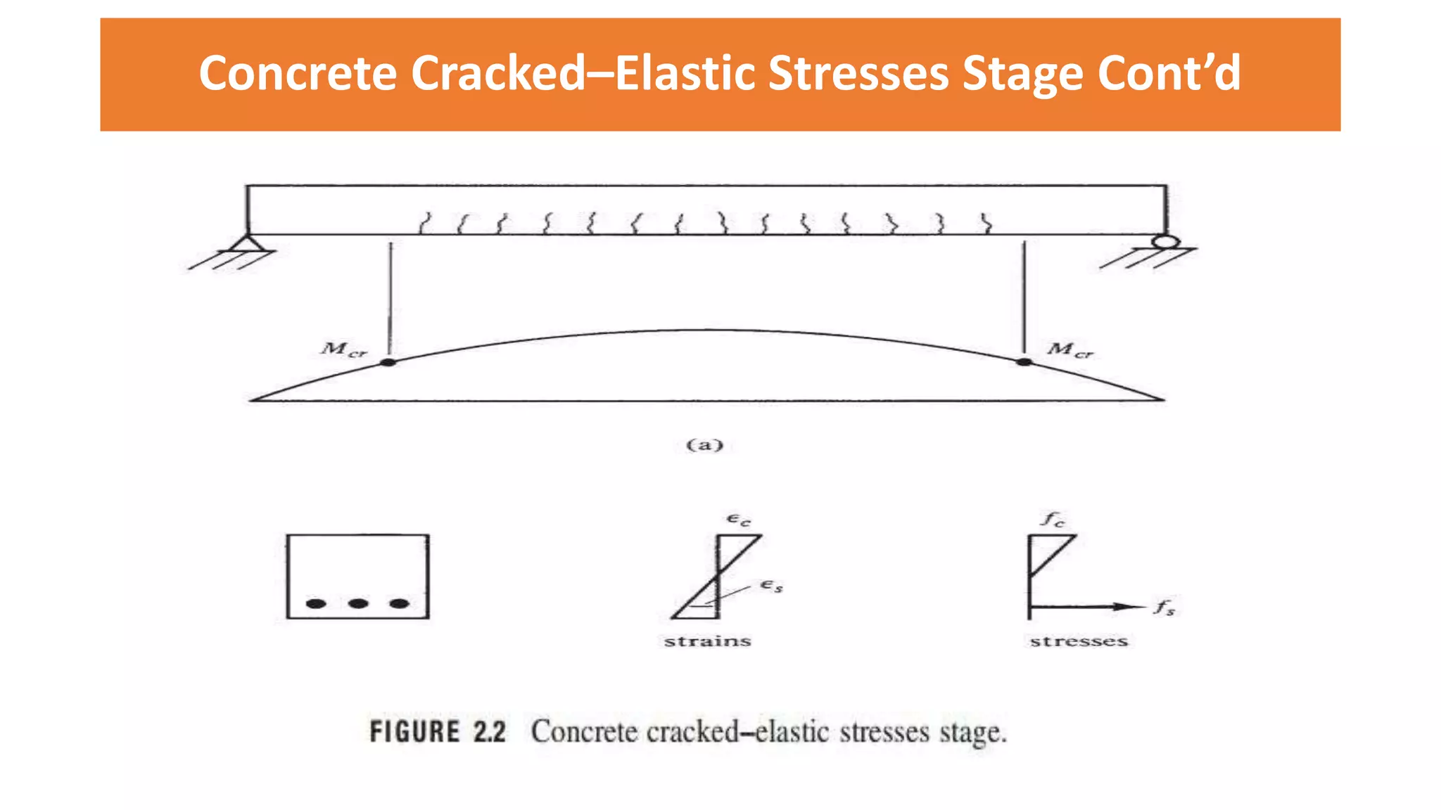


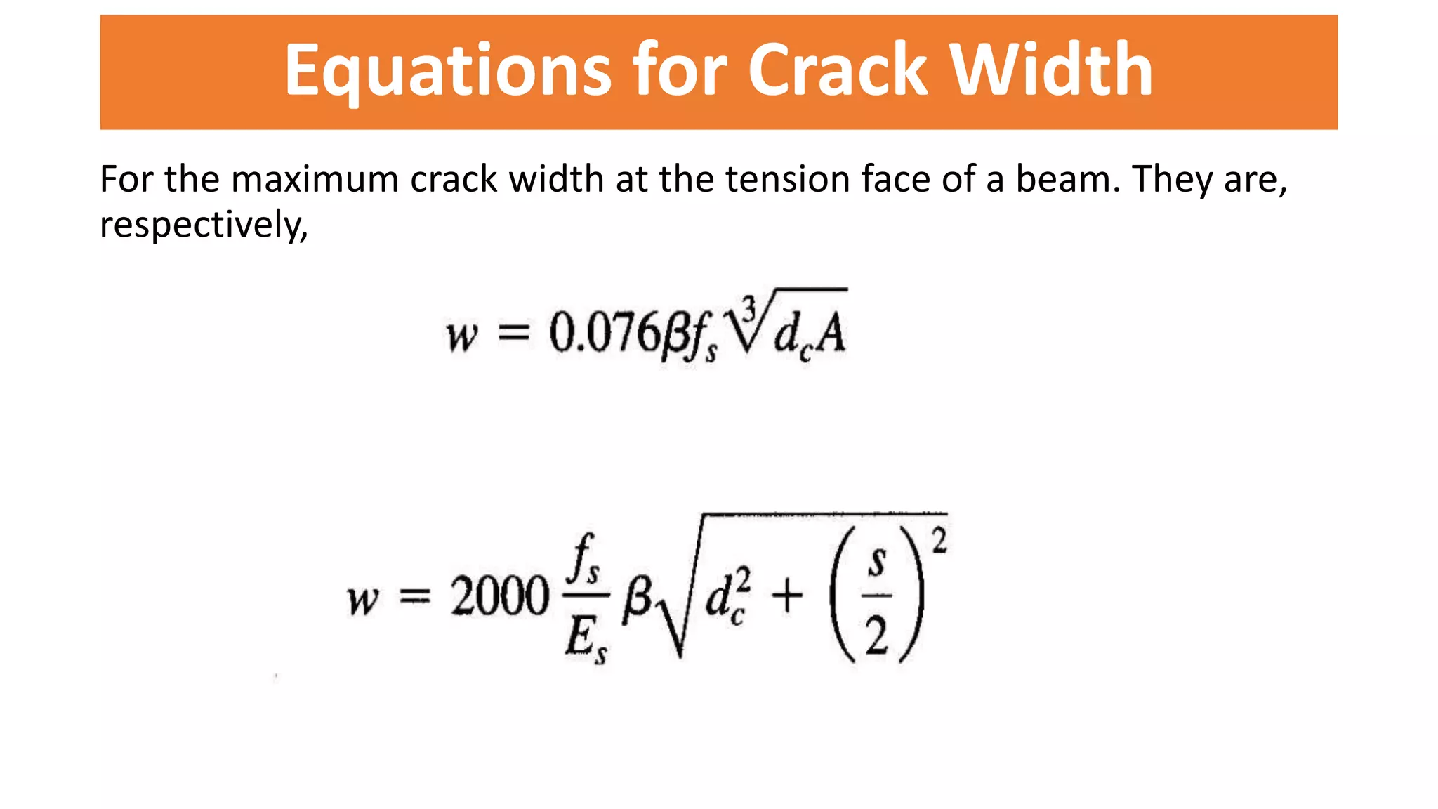
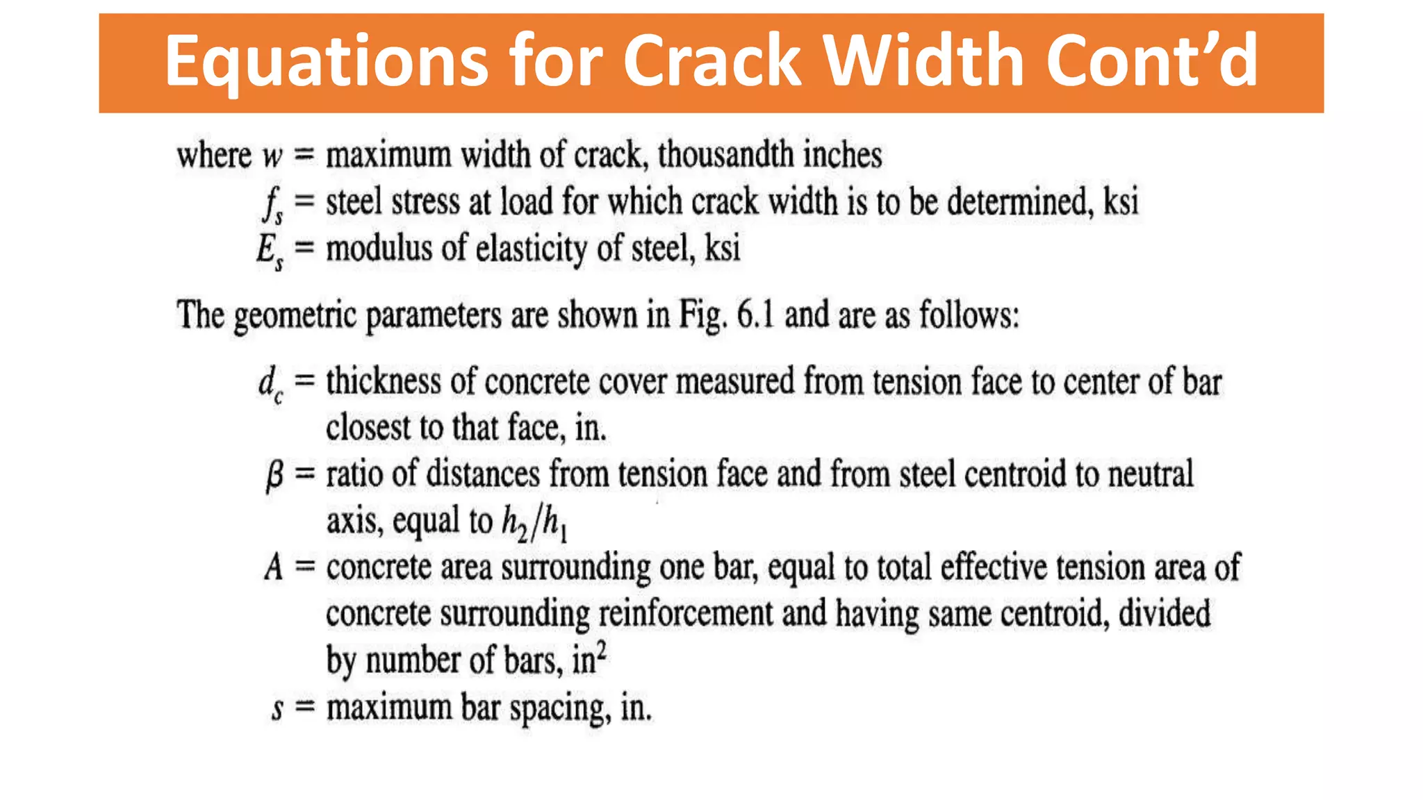

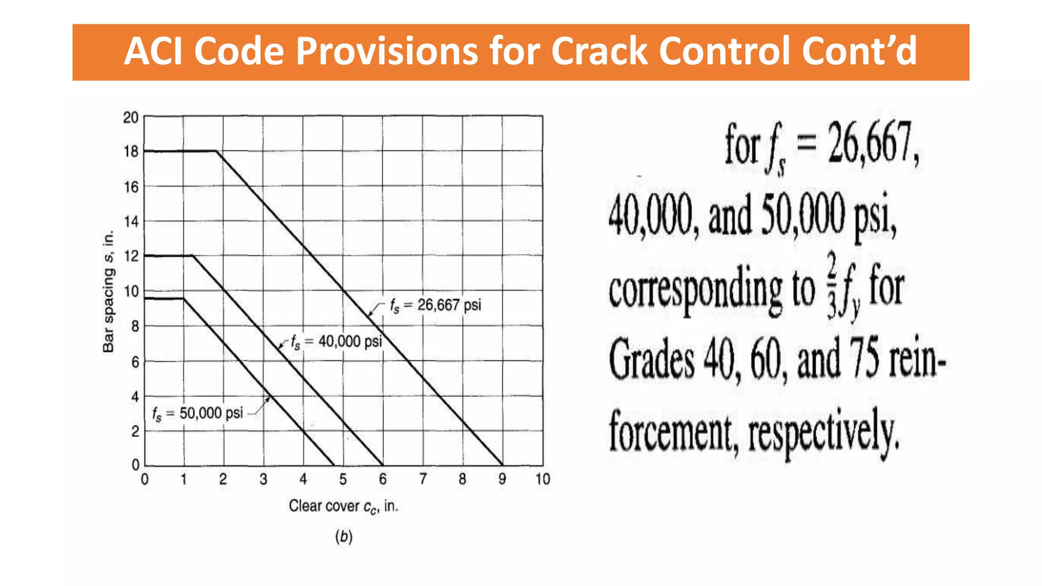


The presentation by Prof. Dr. Engr. Md. Monirul Islam covers the topic of cracking in reinforced concrete flexural members, detailing the stages of cracking, variables affecting crack width, and ACI code provisions for crack control. It emphasizes that cracking is an inevitable process in reinforced concrete beams, which allows for effective use of reinforcement, and outlines the relationship between steel stress and crack width. Additionally, it discusses design considerations and examples to illustrate the principles involved in managing crack formation.