


![Ar. M. Senthil [ senthilmani ], profile picture](https://cdn.slidesharecdn.com/profile-photo-senshots-48x48.jpg?cb=1727349794)
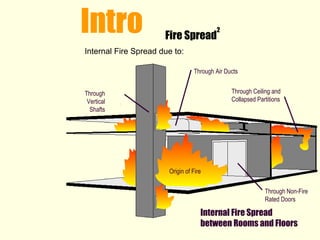
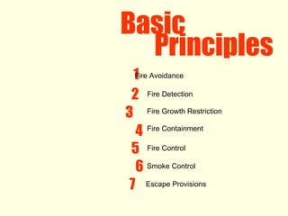
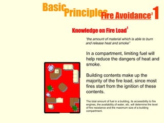
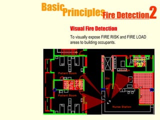
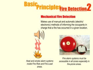
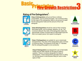
1) The document discusses various fire safety design principles including fire avoidance, detection, growth restriction, containment, control and smoke control. 2) Key elements of fire avoidance include fire zoning, limiting combustible materials and fire load. Fire detection focuses on manual and automatic detection methods. Growth restriction methods center around manual firefighting equipment like extinguishers and sprinklers. 3) Fire containment principles involve compartmentalizing buildings using fire-rated walls and doors to confine fires. Fire control ensures firefighter access to buildings and hydrants.