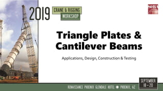
2019 CRW - esign, Fabrication and Testing of Cantilever Beams and Triangle Plates
•Download as PPTX, PDF•
3 likes•631 views

Breakout Session: Design, Fabrication and Testing of Cantilever Beams and Triangle Plates Cantilever beams and triangle plates are valuable specialty rigging tools, but the engineering fundamentals behind their design and use are simpler than they may appear. This presentation will provide examples of commonly used rigging applications and will identify resources for design, fabrication, load testing and lift planning. Speaker: Chad Fox, PE, Project Manager, ruby+associates

Recommended
More Related Content
What's hot
What's hot (20)
Similar to 2019 CRW - esign, Fabrication and Testing of Cantilever Beams and Triangle Plates
Similar to 2019 CRW - esign, Fabrication and Testing of Cantilever Beams and Triangle Plates (20)
More from Specialized Carriers & Rigging Association
More from Specialized Carriers & Rigging Association (20)
Recently uploaded
Recently uploaded (20)
2019 CRW - esign, Fabrication and Testing of Cantilever Beams and Triangle Plates
- 1. Triangle Plates & Cantilever Beams Applications, Design, Construction &Testing
- 2. Introduction • WhyTriangle PL’s & Cantilever Beams? • Started Eng. Dept w/ Limited Rigging Experience • Mostly self taught – research & trial/error • Came to realize how valuable these tools were • Salesmen were passing on jobs where these are needed • Possibly under-utilized by smaller to mid size contractors • Not so complicated – share ?
- 3. Introduction • Topic Overview • Triangle Plates • Applications • Sample Projects • Sample LoadTests • Resources for Design/Construction/Testing (US Standards) • Cantilever Beams • Applications • Sample Projects • Sample LoadTests • Resources for Design/Construction/Testing (US Standards) • Lift Planning/Procedure • Feel Free to Ask QuestionsThroughout
- 4. Triangle Plates – Function • Orientations • 2 Engaged • 3 Engaged – 2 Equally • 3 Engaged – Unequally
- 5. Triangle Plates – Function Engineers: • Moment Summation to determine rotation • ∑MA = 0 = FB x eB – FC x eC FA FB FC eB eC
- 6. Triangle Plates - Applications Load Handoffs: This application involves loads between two crane whether mobile to mobile, mobile to
- 7. Triangle Plates - Applications
- 8. Triangle Plates - Applications
- 9. Triangle Plates - Applications Rotation of a Lifted Object: This application allows a object to be rotated by two lines to the triangle of which lengthens or rotate the object.
- 10. Triangle Plates - Projects • (4) Vertical CTS Heat Exchangers • Overhead Crane Vertical Extents • Cell Clearances • Previously Proposed Solutions: • Roof Opening • Crane Rail Gantry • Client: Preliminary Study • Remove With OH Crane Hook?
- 11. Triangle Plates – Project – Nuclear
- 12. Lift Device(Triangle PL) Mechanics TAILTRUNNION TRUNNION OH CRANE
- 13. Triangle Plates – Load Testing • LoadTest Needed • Test Weight Production • NUREG Requirements • Additional %
- 14. Triangle Plates – Load Testing
- 15. Triangle Plates – Project
- 16. Triangle Plates – Project
- 17. Triangle Plates - Applications 3rd Leg Alignment Adjustment: This application allows an adjustable third line to for rotational variation of lifted object.
- 18. Triangle Plates - Projects Box Section
- 19. Triangle Plates - Projects Hoist
- 20. Triangle Plates - Applications Cascading System of Slings: A triangle can be used to rigging systems with slings and avoid over- a hook. This can help to sling overlap or bunching.
- 21. Triangle Plates - Projects
- 22. Triangle Plates - Projects
- 23. Triangle Plates - Applications Load Equalization Between Two Hooks: In instances where multiple hooks must be utilized due to limitations of the lifting equipment the triangle provides an efficient way distribute the lifted loads relatively to the two hooks.
- 24. Triangle Plates - Projects
- 25. Triangle Plates - Projects
- 26. Triangle Plates – Load Testing
- 27. Triangle Plates – Load Sharing
- 28. Triangle Plates - Applications Rigging System with Shifting Center of Gravity: In this case a triangle allows for systems such as cantilever with an adjustable line center of gravity is shifted throughout the lifting
- 29. Triangle Plates - Design • Resources: • ASME BTH-1, 2017 • AWS D14.1
- 30. Triangle Plates – BTH-1 Design • Design Category (2-2) • A: FS = 2.0Yield/Buckling & 2.4 Fracture/Conn’x • *B: FS = 3.0Yield/Buckling & 3.6 Fracture/Conn’x • C: FS = 6.0Yield/Buckling & 7.2 Fracture/Conn’x • Service Class (2-3) • Fatigue/Cycles • 0 – 4 • Determine Allowable Stress Range
- 31. Triangle Plates - Design • Resources: • ASME BTH-1 Section 3-3.3, Pin PL • Fitted toTest Results (Duerr, 2006) • Limit States: • Tension • Shear – Single Plane • Shear – Double Plane • Out-of-Plane Buckling • Bearing • Pins (3.3.6)
- 32. Triangle Plates - Construction • Resources: • ASME B30.20 • Fabrication: • Boss PL’s • Capacity and/or Limiting Shackles • Drill after welding – plies line up • Local Steel Distribution may be able to burn shape. Photo Courtesy of ALL-LIFTS
- 33. Triangle Plates – Load Testing • Resources: • ASME B30.20 (should) • OSHA, 29 CFR 1926.251 (shall) • 125% Design Capacity • Recommend worst case positions • Certificate • Be aware overloading Shackles
- 34. Triangle Plates–Marking • ASME B30.20 Marking: • Weight • Rated Load • Service Class • Design Category • Serial Number • Manufacturer
- 35. Triangle Plates – Inspection • ASME B30.20 Inspection: (20-1.3) • Designated Person • Initial Inspection (New or Modified) • Every Lift Inspection • Frequent Inspection • Periodic Inspection (recorded) • Table 20-1.3.3-1 For Minimum Frequency per Service (normal, heavy, severe)
- 37. Cantilever Beams – Function • Reach Objects without direct overhead access • Equipment installation through sides of buildings/platforms • Center of Gravity Over Hook
- 38. Cantilever Beams – Function • Shifting COG Depending on Configuration. • Beam Only • Beam + CWT • Beam + CWT + Object
- 39. Cantilever Beams – Function • Heavy Counterweight • Light object Compared to CWT • Watch Sloping of Beam • Simplest Option if Possible
- 40. Cantilever Beams – Function • Sliding Counterweight or Hook • Powered system to move the counterweight in relation to the pick point to counterbalance the lifted load. • Similar with sliding hook. • Hydraulically Powered Common.
- 41. Cantilever Beams – Function • Adjustable Line to Lift Beam • Winch Mounted to the Lift Beam • Self Contained • Need to Account forWinchWeight • Mounting Space Needed • Power
- 42. Cantilever Beams – Function • Adjustable Line to Lift Beam • Using a Secondary Line From Crane • Similar toTripping Using Auxiliary Line • Run Second LineThrough Block @Triangle • Sheaves: Ch. 4 BTH-1
- 43. Cantilever Beams – Function • Adjustable Line to Lift Beam • Hoist Line Above Hook • Air • Electric • Hand (probably lots of work) • Caution on Angle Loading of Hoists: • Contact Manufacturer on allowable angles. • Height Limitations Due to Power/Air/Access Needs
- 44. Cantilever Beams – Example • LoadTest – Adjustable line • Beam • Counterweight • Hoist • Lifted Object • Grill
- 45. Cantilever Beams – Example • Beam Construction • Steel Shapes Most Efficient: • Box Sections • Tubes • StoutWide Flange • Slender Shapes More Prone to Failure by Buckling of the Compression Flange (Twisting of the Shape)
- 46. Cantilever Beams – Example • Beam Construction • Shackle/Sling attachment lugs • Welded Single Lugs (one-time use) • Welded Continuous (heavy) • Bolted (removable)
- 47. Cantilever Beams – Example • Bolted Lift Lug • Can Be Re-Used • Locations Easily Adjusted • Transferred to Other Beams
- 48. Cantilever Beams – Example • Bolted Lift Lug • If Pretensioned: • DTIWashers helpful • Not All Bolts Can Be re-used (A490, Galvanized) • Typically Spec A325
- 49. Cantilever Beams – Example • End Plates • Allow For Extensions • End Fixtures • Allow Join (2)Together
- 50. Cantilever Beams – Lift Planning • Lift Plans Important For Use • Clearances • Lengths • Line Adjustment Needed • Forces (change) • Stability Verification
- 51. Cantilever Beams – Lift Planning • Beam Only • COG • Hoist Length • Sling Forces
- 52. Cantilever Beams – Lift Planning • Beam + CWT
- 53. Cantilever Beams – Lift Planning • Beam + CWT + LOAD
- 54. Cantilever Beams – Lift Planning • Beam + CWT • (Load Released)
- 55. Cantilever Beams – Lift Planning • Deflection • Cantilever • End Supported D = 4” D = 1” Cantilever End Supported
- 56. Cantilever Beams – Lift Planning • Bidding Work • Beam + CWTWill at least Double total lifted Load • Crane Upsizing Likely
- 57. Cantilever Beams- Design • Resources: • ASME BTH-1 • Welds: AWS D14.1
- 58. Cantilever Beams– BTH Design • Design Category (2-2) • A: FS = 2.0Yield/Buckling & 2.4 Fracture/Conn’x • *B: FS = 3.0Yield/Buckling & 3.6 Fracture/Conn’x • C: FS = 6.0Yield/Buckling & 7.2 Fracture/Conn’x • Service Class (2-3) • Fatigue/Cycles • 0 – 4 • Determine Allowable Stress Range
- 59. Cantilever Beams- Design • Resources: • ASME BTH-1 Section 3-2.3 & 3-2.4 • Yielding • Buckling • Engineers: Caution CLTB • Lug Checks (3-3.3)
- 60. Cantilever Beams- Construction • Resources: • ASME B30.20 • AWS D14.1 • Fabrication: • Local Steel Distribution may have drill line.
- 61. Cantilever– Load Testing • Resources: • ASME B30.20 (should) • OSHA, 29 CFR 1926.251 (shall) • 125% Design Capacity • Recommend full Simulation • Could also use forTraining • Be aware overloading Shackles & Hoist • Bolt-on Lugs – AlsoTested
- 62. Lift Beams – Marking • ASME B30.20 Marking: • Weight • Rated Load(Difficult…multiple) • Service Class • Design Category • Serial Number • Manufacturer
- 63. Cantilever– Inspection • ASME B30.20 Inspection: (20-1.3) • Designated Person • Initial Inspection (New or Modified) • Every Lift Inspection • Frequent Inspection • Periodic Inspection (recorded) • Table 20-1.3.3-1 For Minimum Frequency per Service (normal, heavy, severe)
- 64. Summary • Applications –Triangles • Handoffs • Rotations • Alignment • Cascading Slings • Load Sharing • Shifting Center-of-Gravity
- 65. Summary • Applications – Cantilevers • Inaccessible Access From above • Method Options • Heavy CWT vs Load • Moving CWT • Adjustable Line
- 66. Summary • Design • ASME BTH-1 • Find Correct Design Category • LoadTesting (OSHA required) • ASME B30.20 (if standard) • 125%
- 67. Summary • Inspections • ASME B30.20 • Intervals • Marking • ASME B30.20 • Weight • Rated Load • Serial # • Manufacturer • DC & SC
- 68. Thank You David Duerr PE Bruce Burt PE Erickson’s Inc Alberici/Hillsdale All-Lifts Triangle Plates & Cantilever Beams: Applications, Design, Construction &Testing
Editor's Notes
- -Send in Presentation Samples -Non-technical preferred
- Triangle orientations depend up each apex(corner) loading
- -Moment balance determines rotation, Basic Statics -Corner hardware attachments allow rotation so points of Zero moment
- -This may be of particular value when installing or removing equipment from a structure with a permanent or temporary monorail system that extends outside of the boundaries of the structure, or applications where setting down of the lifted object is not feasible prior to transfer. -Gantry handoffs
- Made up project: -Monorail that extends outside of a building. -Stairway directly Below -Load handoff between mobile crane & monorail hoist.
- -Floor rating -Piping interference -2nd Trolley Additional handoff around obstruction (piping/duct) internally along monorail.
- This may be of particular value during uprighting and/or tilting procedures from a single hook.(no aux or assist crane, working off overhead)
- Nuclear Example
- Animation
- -Load testing requirement – Nureg 612
- -Nuclear Example – Load Testing & Training -2014 First test, presented SCRA ‘15 -Witnessed other load tests – similar thing
- -Travelling from the loading bay to staging location along spent fuel pool. -Works in horizontal position, maximum rotation -Too much rotation – block contact
- -Installation of new -Saddle beams on floor -Kind of a mess with all the chain, air hoses, tag lines
- The triangle can be helpful to achieve high accuracy alignment for certain installation or erection procedures.
- Example: Syracuse University Carrier Dome -New dome on top of the existing inflatable dome -Compression ring comprised of box sections -All different slopes and skews -Try to find a way to minimize rigging (and costs) but adjustable enough to build
- Example: Syracuse University Carrier Dome -2 triangles with a hand hoist -Bolts – Standard holes 1/8” -1 degree off = 1 ½” off corner to corner -Electronic level to monitor
- -Structurally flexible objects requiring multiple pick points to maintain integrity during lift.
- Digester Cover Example -12 trusses -Engage 10 for integrity -triangles both avoid too many slings in the hook and also allow for better load distribution -Sling lengths, adjustment, never get everything equal
- -5 Triangles down to 10 slings -Triangle rotation along with adjustable chain – engage all 10 locations -Rigging & structural work together
- -Avoid large load variations between crane hooks. -This application may also allow for greater horizontal clearances between crane hooks and/or booms by spacing out hook attachment points.
- Project example: Sun Life Stadium Canopy -4 trusses, one along each sideline & end zone -Erection trusses– build ground or air on towers -Strand Jacks, crane capacity -Trade off between more equipment but safer/faster working conditions
- -4 Cranes: MLC 650 -2 Triangles (triangle trusses) -Designed to allow safe spacing between crane hooks/booms -Problems with load transfer between hooks if connecting directly to truss. Stiffness causes problems.
- Load testing -Anchored & use 2 OH -Inspection following load testing
- Project example: Transformer Lift -Lift beam, really functioning as a 3-pt triangle -Adjust to get percentage of load to each crane – maximize efficiency & crane chart utilization
- Triangle rotates rather than hook, or slings moving in hook
- Design standards to help with design
- Design standards to help with design
- BTH-1 Section 3-3.3 Fairly easy to build a spreadsheet if you’re using frequently - example
- ASME B30.20
- ASME B30.20 – Load Testing
- ASME B30.20 - Marking
- ASME B30.20 - Inspection
- -Load testing of smaller cantilever beam -Electric hoist -Hanging Weight basket -Grill
- -Not there in field never know if bolts are going to be torqued
- -20ft- need 25ft -Build 10-ton, need 20-ton -AISC Design Guide 16 – End PL’s
- -Typical procedure -System COG, Hoist length, Forces
- -Approximately 4 times as much deflection compared to a typical lift beam that’s loaded at the middle -Same Beam, same load, 4 times the deflection
- Design standards to help with design
- Design standards to help with design
- BTH-1 Section 3
- ASME B30.20
- ASME B30.20
- ASME B30.20
- ASME B30.20
- Triangle Applications
- ASME B30.20
- ASME B30.20
- ASME B30.20