Downloaded 3,504 times


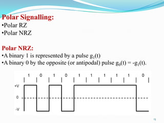
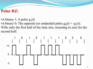
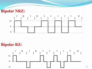
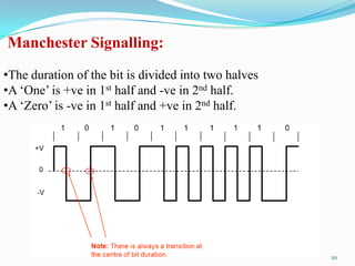
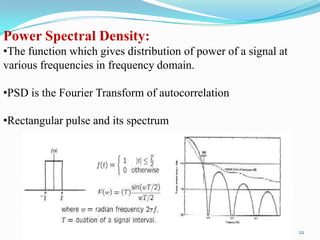
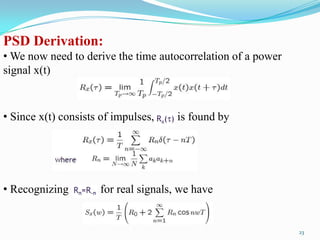


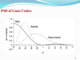
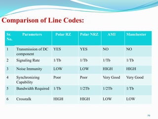


This document discusses line coding techniques used for digital data transmission. It begins by explaining the need for line coding due to the discrete and band-limited nature of information being transmitted. Then it covers various line coding techniques including unipolar, polar, bipolar, and Manchester coding. It discusses the properties, advantages, disadvantages and power spectral density of each technique. Finally, it provides a comparison of polar RZ, polar NRZ, AMI and Manchester coding in terms of their transmission of DC components, signaling rate, noise immunity, synchronization capability, bandwidth requirement, and crosstalk.