1) Use case diagrams are used in analysis to identify system functionality and separate actors from use cases. Actors represent external users or systems, while use cases describe system behaviors in response to actor stimuli.
2) Relationships like "uses" and "extends" help organize use cases and reduce redundant text descriptions. The "uses" relationship allows behaviors to be reused across use cases. The "extends" relationship allows new behaviors to override parts of other use cases.
3) While use case diagrams map relationships between use cases, they contain little information on their own. The real value is in the detailed text descriptions of system behaviors and relationships between use cases.
PLAI - Acceleration Program for Generative A.I. Startups
Usecases
1. UML Use Case Diagrams
Engineering Notebook
C++ Report
Nov-Dec 98
An important part of the Unified Modeling Language (UML) is the facilities for drawing use case
diagrams. Use cases are used during the analysis phase of a project to identify and partition system
functionality. They separate the system into actors and use cases.
Actors represent roles that can are played by users of the system. Those users can be humans, other
computers, pieces of hardware, or even other software systems. The only criterion is that they must be
external to the part of the system being partitioned into use cases. They must supply stimuli to that part of
the system, and the must receive outputs from it.
Use cases describe the behavior of the system when one of these actors sends one particular stimulus. This
behavior is described textually. It describes the nature of the stimulus that triggers the use case; the inputs
from and outputs to other actors, and the behaviors that convert the inputs to the outputs. The text of the
use case also usually describes everything that can go wrong during the course of the specified behavior,
and what remedial action the system will take.
For example, consider a point of sale system. One of the actors is the customer and another is the sales
clerk. Here is just one use case from this system:
Use Case 1: Sales Clerk checks out an item
1. Customer sets item on counter.
2. Sales clerk swipes UPC reader across UPC code on item
3. System looks up UPC code in database procuring item description and price
4. System emits audible beep.
5. System announces item description and price over voice output.
6. System adds price and item type to current invoice.
7. System adds price to correct tax subtotal
Error case 1: UPC code unreadable
If after step 2, the UPC code was invalid or was not properly read, emit an audible ‘bonk’ sound.
Error case 2: No item in database
If after step 3 no database entry is found for the UPC flash the ‘manual entry’ button on the
terminal. Accept key entry of price and tax code from Sales Clerk. Set Item description to
“Unknown item”. Go to step 4.
Clearly a point of sale system has many more use cases than this. Indeed, for a complex system, the
number can reach into the thousands. The complete functionality of the system can be described in use
cases like this. This makes use cases a powerful analysis tool.
Drawing Use Case Diagrams.
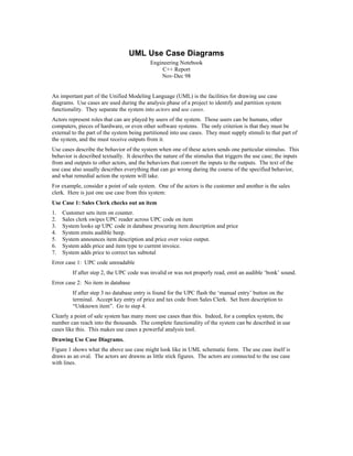
Figure 1 shows what the above use case might look like in UML schematic form. The use case itself is
draws as an oval. The actors are drawns as little stick figures. The actors are connected to the use case
with lines.
2. Sales Clerk
Check Out Item
Customer
Figure 1
Clearly this is a pretty simple notation; but there is more to it. Use and actor icons can be assembled into
large “system boundary diagrams”. Such diagrams show all the use cases in a system surrounded by a
rectangle. Outside the rectangle are all the actors of the system, and they are tied to their use cases with
lines. The box represents the system boundary; i.e. it shows all the use cases that are inside a particular
system. Everything inside the box is part of the system. Everything outside is external to the system. See
Figure 2.
Sales Clerk
Check Out Item
«uses»
Swipe
UPC
Reader
«extends»
Customer
«uses»
Check Out
«uses»
"21" item
Manager
Inventory
Item
Inventory
Clerk
Figure 2
Aside from showing the system boundary, a few more actors, and a few more use cases; this diagram
shows some relationships between the use cases. These relationships are «uses» and «contains». The uses
relationship is the simplest of the two. Note that it appears twice in Figure 2, once from Check Out Item to
Swipe UPC Reader. The other is from Inventory Item to Swipe UPC Reader. The Swipe UPC Reader use
case describes the behavior of the actor and the system when the actor swipes the UPC reader across the bar
codes on a product.
As we saw in our first use case, the Swipe UPC Reader behavior needs to occur within the Check Out Item
description. However, since inventory clerks also swipe bar codes while counting objects on the shelves,
this same behavior must be part of the Inventory Item use case. Rather than write the description for this
behavior twice; we can employ the «uses» relationship to show that it belongs in both use cases. Having
done this we might change the description of the Check Out Item use case as follows:
3. Use Case 1: Sales Clerk checks out an item
1. Customer sets item on counter.
2. «uses» Swipe UPC Reader.
3. System looks up UPC code in database procuring item description and price
4. System emits audible beep.
5. System announces item description and price over voice output.
6. System adds price and item type to current invoice.
7. System adds price to correct tax subtotal
So, the «uses» relationship is very much like a function call or a subroutine. The use case being used in
this fashion is called an abstract use case because it cannot exist on its own but must be used by other uses
cases.
The other interesting relationship is the «extends» relationship between Check Out Item and Check Out
“21” item. In many stores, sales clerks under the age of 21 are not allowed to check out liquor. When an
underage sales clerk sees a liquor item, the clerk shouts “21” over the P.A. system. Soon a manager walks
up and swipes UPC code on the item. This represents a change to the use case that could be addressed in
one of two ways.
First, we could add ‘if’ statements to the Check Out Item use cases such that it looked like this:
Use Case 1: Sales Clerk checks out an item
1. Customer sets item on counter.
2. If item is liquor
2.1. Call “21” over P.A. system
2.2. Wait for manager.
2.3. Manager «uses» Swipe UPC Reader
2.4. Goto step 4
3. «uses» Swipe UPC Reader.
4. System looks up UPC code in database procuring item description and price
5. System emits audible beep.
6. System announces item description and price over voice output.
7. System adds price and item type to current invoice.
8. System adds price to correct tax subtotal
Although this works fine, it has a severe disadvantage. Remember the Open Closed Priniple (OCP)? [note:
cite reference from Engineering Notebook in 1996] It states that we don’t want to create software that has
to be modified when the requirements change. Rather, in well designed software, a change in requirements
should cause of to add new code rather than change old working code. The same rules apply to the
functional specifications of use cases. When the requirements change we want to add new use cases, not
change old existing use cases.
Thus, rather than add the if statement in the use case, we use the «extends» relationship. This relationship
allows us to specify a new use cases that contains commands for overriding and modifying the extended
use case. Thus the Check out “21” item use case in Figure 2 overrides and extends the Check Out Item”use
case. The text for the Check Out Item use case might appear as follows:
Use Case 2: Check Out “21” Item
1. Replace Step 2 of Check Out Item with:
1.1. Call “21” over P.A. System
1.2. Wait for manager
1.3. Manager «uses» Swipe UPC Reader
This achieves our goal of allowing new features to be added to the use case model without needing to
change existing use cases.
4. Extension Points
Notice that the Check Out “21” Item use cases mentions the “Check Out Item” use case directly. This is
unfortunate. What if we wanted to extend several other similar use cases in the same way? We’d have to
have as many extending use cases as extended use cases. And all the extending use cases would be nearly
identical.
We can remedy this situation by adding extension points to the extended use cases. Extension points are
simply symbolic names that identify positions in the extended use case that the extending use cases can call
out. Thus, our two use cases might look like this:
Use Case 1: Sales Clerk checks out an item
1. Customer sets item on counter.
2. XP21: Sales clerk swipes UPC reader across UPC code on item
3. System looks up UPC code in database procuring item description and price
4. System emits audible beep.
5. System announces item description and price over voice output.
6. System adds price and item type to current invoice.
7. System adds price to correct tax subtotal
Use Case 2: Check Out “21” Item
2. Replace XP21 of extended use case with:
2.1. Call “21” over P.A. System
2.2. Wait for manager
2.3. Manager «uses» Swipe UPC Reader
Text Management.
One of the problems with document maintenance is that when a single requirement changes, it may affect
many places within the text of the functional specification. Indeed, sometimes the amount of redundant
information in a functional spec can be very high, causing significant maintenance problems. The goal of
use cases and their relationships is to manage the textual descriptions within a functional specification, and
thereby reduce the redundant information. By structuring the use cases and their relationships properly,
you can create functional specifications that never need to be changed in more than one place. For very
large projects, this can be a significant gain.
The Structure of a use case is not the structure of the software it represents.
It is tempting to look at the structure of a use case document as a precursor or progenitor of the structure of
the software it represents. However, this is not likely to be the case. Use cases are structured to minimize
textual redundancy. While this is a laudable goal, it has nothing to do with software design considerations.
Thus, the structure of the use cases is not related to the structure of the resultant software. Use cases do not
represent objects or classes in the eventual designs. The relationships between use cases do not forshadow
relationships in the software design. The structure of the use cases and the structure of the software are
unrelated.
Use Case Diagrams have low information content.
Use case diagrams don’t tell you very much. They convey the structure of the use cases, but tell you very
little about the text within them. As such, they are not particularly interesting documents when they are
separated from their textual descriptions. At best the diagrams provide a nice roadmap of relationships so
that readers can reconstruct the whole text of a given scenario by tracing through the «uses» and «extends»
relationships inserting the text of the former, and modifying the text according to the latter.
Conclusion
Use cases are powerful tools for analysts to use when partitioning the functionality of a system. Use case
relationships and the corresponding diagrams help analysts to structure use cases such that their textual
descriptions contain a minimum of redundant information; thus making the whole text document much
5. easier to maintain. But use cases are not design tools. They do not specify the structure of the eventual
software, nor do they imply the existence of any classes or objects. They are purely functional descriptions
written in a formalism that is completely separate from software design.